IMR IX176 Portable Gas Detector User Manual...Ver. 1.0A4 Environmental Equipment, Inc. IMR IX176...
15
Ver. 1.0A4 Environmental Equipment, Inc. IMR IX176 Portable Gas Detector User Manual Read this manual carefully before using this device. (727) 328-2818 / (800) RING-IMR • Fax: (727) 328-2826 www.imrusa.com • [email protected]
Transcript of IMR IX176 Portable Gas Detector User Manual...Ver. 1.0A4 Environmental Equipment, Inc. IMR IX176...

Ver. 1.0A4
Environmental Equipment, Inc.
IMR IX176 Portable Gas Detector
User Manual
Read this manual carefully before using this device.
(727) 328-2818 / (800) RING-IMR • Fax: (727) 328-2826
www.imrusa.com • [email protected]

Environmental Equipment, Inc. IX176
IMR IX176 User Manual
3632 Central Ave. St. Petersburg, FL 33711 Phone: 727-328-2818 / 800-RING-IMR
www.imrusa.com Fax: 727-328-2826
THE PRIDE OF THE COMPANY – MADE IN THE USA Page 2 of 15
CONTENTS
SERVICE GUIDELINES ........................................................................................................................................................... 3
SAFETY INFORMATION ........................................................................................................................................................ 3
1. Brief Introduction ......................................................................................................................................................... 4
2. Features and Specifications .......................................................................................................................................... 4
2.1. Main Features: ..................................................................................................................................................... 4
2.2. Technical Specifications: .................................................................................................................................... 4
3. Structure and Functions ............................................................................................................................................... 5
3.1. Appearance .......................................................................................................................................................... 5
3.2. Display Information ............................................................................................................................................ 5
3.3. Button functions .................................................................................................................................................. 5
4. Operating instruction.................................................................................................................................................... 6
4.1. Power On the Detector ........................................................................................................................................ 6
4.2. Power Off The Detector ...................................................................................................................................... 6
4.3. Menu ................................................................................................................................................................... 6
4.4. Alarm Codes ........................................................................................................................................................ 8
4.5. Check Device Status ............................................................................................................................................ 9
4.6. Zero Calibration .................................................................................................................................................. 9
4.7. Bump Test ........................................................................................................................................................... 9
5. Calibration and Alarms .............................................................................................................................................. 10
5.1. Calibration and Alarming Level: ....................................................................................................................... 10
5.2. Zero Calibration ................................................................................................................................................ 10
5.3. Calibration Span Adjustment ............................................................................................................................ 10
5.4. Calibration Span Set Up .................................................................................................................................... 10
5.5. L-alarm Set Up .................................................................................................................................................. 11
5.6. H-alarm Set Up ................................................................................................................................................. 11
6. Battery Charging ........................................................................................................................................................ 11
7. Data Upload ............................................................................................................................................................... 11
8. Sensor Usage and Replacement ................................................................................................................................. 11
9. Carry Clip Configuration ........................................................................................................................................... 11
10. Troubleshooting Guide .......................................................................................................................................... 12
11. Usage Notices ........................................................................................................................................................ 12
Target Gas List ............................................................................................................................................................... 13
12. Warranty ................................................................................................................................................................ 14
13. Contact Information ............................................................................................................................................... 15

Environmental Equipment, Inc. IX176
IMR IX176 User Manual
3632 Central Ave. St. Petersburg, FL 33711 Phone: 727-328-2818 / 800-RING-IMR
www.imrusa.com Fax: 727-328-2826
THE PRIDE OF THE COMPANY – MADE IN THE USA Page 3 of 15
SERVICE GUIDELINES
1. Thank you for purchasing this product. Before operation, please read this manual carefully to
help prevent any accidents or damage to the device due to miss use.
2. Do not modify, repair, or replace parts in the device without contacting IMR, we assume no
liability for any harm caused due to improperly modified equipment.
3. Any damage caused due to incorrect operation shall not be covered.
SAFETY INFORMATION
Before using the detector please carefully read the below safety information first and follow the
operation requirement:
1. Do not use if damaged or defective. Before use check physical damage or missing parts.
2. Each day before use it is recommended to perform a “bump test” to ensure the detector is
operation properly. See section 4.7
3. It is recommended that a “bump test” be performed periodically to ensure that the audible, visual
and vibration alarms are set to the correct level and are functioning properly.
4. Only use authorized accessories provided by IMR. Use of unauthorized accessories may result in
damage to the device.
5. Only use the charger provided with the instrument to charge the detector. Only charge in a safe
environment. Charging in a hazardous environment is not advisable.
6. Detectors using catalytic sensors or semi-conductor sensors cannot be exposed to gases with
concentrations over the detector’s range. Doing so will overload the detector and interfere with
its performance or even cause damage.
7. Detectors using catalytic sensors or semi-conductor sensors cannot be exposed to gas
environments that contain lead compounds, sulfur compounds, phosphorous compounds or
silicon. These environments will damage a catalytic sensor or semi-conductor sensor.
8. Detectors using catalytic sensors or semi-conductor sensors cannot be exposed to gas
environment which contain hydrogen sulfide, halogenated hydrocarbon or highly corrosive
environments. These environments will dampen the sensor’s response and decrease the sensor’s
sensitivity to gases. If the detector has to be used in the above environments. Then preform a
“bump test” after use.
9. Do not expose the detector to electric shock, strong electromagnetic fields or intense continuous
mechanical vibration.
10. Do not discard the battery in the standard trash. Please follow all local regulatory and
environment regulations pertaining to lithium battery disposal.
11. Disassembly, modification, or repair of the detector by the end user is prohibited.
12. Take precautions to prevent the detector from being dropped at high elevations and intense
vibration.
13. For any usage or trouble shooting not covered in this manual contact IMR.

Environmental Equipment, Inc. IX176
IMR IX176 User Manual
3632 Central Ave. St. Petersburg, FL 33711 Phone: 727-328-2818 / 800-RING-IMR
www.imrusa.com Fax: 727-328-2826
THE PRIDE OF THE COMPANY – MADE IN THE USA Page 4 of 15
1. BRIEF INTRODUCTION The IX176 portable single gas detector can make continuous detection to combustible and toxic
gases. It is suitable for combustible and toxic gas leakage detection in underground pipe or mines,
keeps workers safe and prevents damage to facilities. The detector uses high quality sensors. The
shell is special high strength material with anti-slip rubber. It has a functional and watertight design
(IP 65).
2. FEATURES AND SPECIFICATIONS
2.1. MAIN FEATURES:
Large LCD display
Adjustable low and high alarm level
High concentration protection for combustible gas
Self-test of the combustible gas sensor
Low battery alert
Real time clock
Replaceable sensor module
Self-adjustment function
Data upload to PC (optional)
STEL and TWA alarming for toxic gases
Intrinsically safe
2.2. TECHNICAL SPECIFICATIONS:
Detection method: Natural diffusion
Target gas: LEL, O2, toxic gases etc.
Accuracy: ≤±5% F.S.
Response time: T<30s
Indication:
o LCD indicates the time and state
o Audible, visual and vibration alarm signals
Working temperature:
o -40℃~70℃ (for combustible gas)
o -20℃~50℃ (for toxic gas)
Working humidity: <95%RH
IP rating: IP65
Power supply: DC3.7V, 1300mAh Li-ion battery
Continuously working time:
o Combustible gas: ≮ 8h continuously
o Toxic gas: ≥300h continuously
Charging time: 4~6 hours
Sensor life: 3 years
Dimension and weight: 104.0mm×60.8mm×30.5mm about 125g

Environmental Equipment, Inc. IX176
IMR IX176 User Manual
3632 Central Ave. St. Petersburg, FL 33711 Phone: 727-328-2818 / 800-RING-IMR
www.imrusa.com Fax: 727-328-2826
THE PRIDE OF THE COMPANY – MADE IN THE USA Page 5 of 15
3. STRUCTURE AND FUNCTIONS
3.1. APPEARANCE
1. Alarm LED
2. Display
3. Buttons
4. Gas port
5. Data / Charging
port
6. Buzzer
7. Hand strap
3.2. DISPLAY INFORMATION
1. Battery voltage
2. Lock
3. Buzzer
4. Vibrator
5. Alarm type
6. Warning
7. Value figure
8. Fault
9. Record
10. Clock
11. Zero calibration
12. Calibration span & status
13. Charging
14. Settings
15. Unit of measurement
Note: Data upload function is only available
only if requested at time of purchase.
3.3. BUTTON FUNCTIONS Button Description
To power on the detector
press and hold for 3 seconds
Press to cancel an operation
Calibration: When the device
is powered off press and
for more than 3s
To power off the detector
press and hold for 3 seconds
Press to increase the display
value
To check the device status
press and . This will
display Temperature, time,
STEL & TWA levels②, and
maximum level③
Press and for more
than 3s to access the
configuration menu
Press to decrease the display
value
To start zero calibration press
& then hold for more
than 3s ①
Confirm entered information
Press to enable/disable the
beep and vibration
Note:
① Password is needed when this operation
does.
② Only the detector for toxic gas has this
function.
③ Only O2 sensor has maximum and
minimum level.
Environmental Equipment, Inc. IX176
IMR IX176 User Manual
3632 Central Ave. St. Petersburg, FL 33711 Phone: 727-328-2818 / 800-RING-IMR
www.imrusa.com Fax: 727-328-2826
THE PRIDE OF THE COMPANY – MADE IN THE USA Page 6 of 15
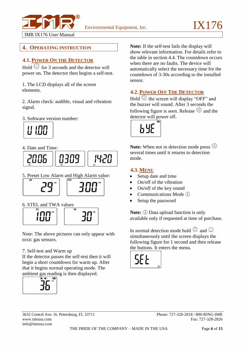
4. OPERATING INSTRUCTION
4.1. POWER ON THE DETECTOR
Hold for 3 seconds and the detector will
power on. The detector then begins a self-test.
1. The LCD displays all of the screen
elements.
2. Alarm check: audible, visual and vibration
signal.
3. Software version number:
4. Date and Time:
5. Preset Low Alarm and High Alarm value:
6. STEL and TWA values
Note: The above pictures can only appear with
toxic gas sensors.
7. Self-test and Warm up
If the detector passes the self-test then it will
begin a short countdown for warm up. After
that it begins normal operating mode. The
ambient gas reading is then displayed.
Note: If the self-test fails the display will
show relevant information. For details refer to
the table in section 4.4. The countdown occurs
when there are no faults. The device will
automatically select the necessary time for the
countdown of 3-30s according to the installed
sensor.
4.2. POWER OFF THE DETECTOR
Hold the screen will display “OFF” and
the buzzer will sound. After 3 seconds the
following figure is seen. Release and the
detector will power off.
Note: When not in detection mode press
several times until it returns to detection
mode.
4.3. MENU
Setup date and time
On/off of the vibration
On/off of the key sound
Communications Mode ①
Setup the password
Note: ① Data upload function is only
available only if requested at time of purchase.
In normal detection mode hold and
simultaneously until the screen displays the
following figure for 1 second and then release
the buttons. It enters the menu.

Environmental Equipment, Inc. IX176
IMR IX176 User Manual
3632 Central Ave. St. Petersburg, FL 33711 Phone: 727-328-2818 / 800-RING-IMR
www.imrusa.com Fax: 727-328-2826
THE PRIDE OF THE COMPANY – MADE IN THE USA Page 7 of 15
Press or to change menu items. The
following table outlines each item:
Display Description
Press to adjust the time
Press to turn on or turn
off the key press sound
Press to turn on of turn
off vibration
Press to enter
communications mode
with a PC ①
Press to modify the
password (initial : 0000)
Note: ① Data upload function is only
available only if requested at time of purchase.
After entering into an item press or to
change settings. Press to confirm and press
to exit without saving. The following table
outlines each option:
Display Description
Enable the function
Disable the function
Environmental Equipment, Inc. IX176
IMR IX176 User Manual
3632 Central Ave. St. Petersburg, FL 33711 Phone: 727-328-2818 / 800-RING-IMR
www.imrusa.com Fax: 727-328-2826
THE PRIDE OF THE COMPANY – MADE IN THE USA Page 8 of 15
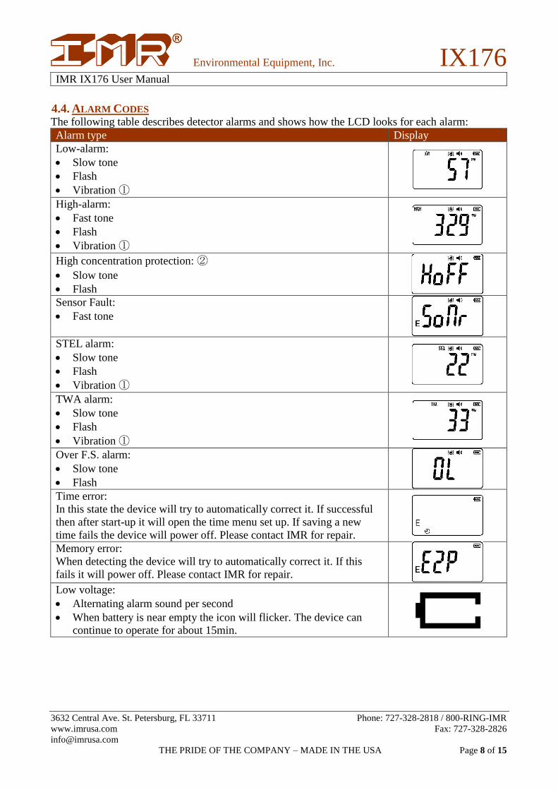
4.4. ALARM CODES The following table describes detector alarms and shows how the LCD looks for each alarm:
Alarm type Display
Low-alarm:
Slow tone
Flash
Vibration ①
High-alarm:
Fast tone
Flash
Vibration ①
High concentration protection: ②
Slow tone
Flash Sensor Fault:
Fast tone
STEL alarm:
Slow tone
Flash
Vibration ①
TWA alarm:
Slow tone
Flash
Vibration ①
Over F.S. alarm:
Slow tone
Flash Time error:
In this state the device will try to automatically correct it. If successful
then after start-up it will open the time menu set up. If saving a new
time fails the device will power off. Please contact IMR for repair.
Memory error:
When detecting the device will try to automatically correct it. If this
fails it will power off. Please contact IMR for repair. Low voltage:
Alternating alarm sound per second
When battery is near empty the icon will flicker. The device can
continue to operate for about 15min.

Environmental Equipment, Inc. IX176
IMR IX176 User Manual
3632 Central Ave. St. Petersburg, FL 33711 Phone: 727-328-2818 / 800-RING-IMR
www.imrusa.com Fax: 727-328-2826
THE PRIDE OF THE COMPANY – MADE IN THE USA Page 9 of 15
Note:
① It will only vibrate if the vibration setting is
enabled.
② Only for combustible gases.
If the alarm is triggered for extended periods
press to suppress the audible and vibration
alarms and will flash.
4.5. CHECK DEVICE STATUS
Pressing and together will display the
Temperature, Time, STEL & TWA levels①,
maximum level and minimum level②.
Note:
① Only available for toxic gases.
② Only O2 sensors have min/max levels.
4.6. ZERO CALIBRATION In clean air if the detector does not 0 then
select zero calibration to reset the zero point.
In detection mode pressing both and
for 1 second will prompt to “please input
password’ once this is displayed release the
buttons. Input the password to access zero
point calibration.
The detector will display the following:
Status? Display
Pressing both and
will display this.
After 1 second it will
continue to the next
step.
At this step enter the
password. The digit
that is flickering
figure can be
modified by pressing
or .
The zero point will
automatically
calibrate. Press to
save the new setting.
Note: When it is calibrated the concentration
of oxygen in clean air for O2 is 20.9%VOL.
Warning: This operation should be carried
out in clean air. Otherwise the accuracy of the
detector will be affected due to gas
concentrations in the air.
4.7. BUMP TEST In order to make sure the IX176 is working
correctly it is suggested to do a “bump test”
before every use.
Test method: With the device is powered on
expose it to the target gas or standard gas
environment with high a concentration that is
beyond the high alarm level. If the device
reacts correctly and the reading is accurate
then the detector may be used in the field.
If the reading is beyond the regular error
ranges recalibrate the device. See section 5.
If the device does not respond or display is
faulty (error) contact IMR.
Environmental Equipment, Inc. IX176
IMR IX176 User Manual
3632 Central Ave. St. Petersburg, FL 33711 Phone: 727-328-2818 / 800-RING-IMR
www.imrusa.com Fax: 727-328-2826
THE PRIDE OF THE COMPANY – MADE IN THE USA Page 10 of 15
5. CALIBRATION AND ALARMS This section covers recalibrating the detector
and adjusting alarm levels.
5.1. CALIBRATION AND ALARMING
LEVEL: When the device is powered off press and hold
and for 5 seconds and the detector will
begin a self-test. If the self-test passes the
enter password prompt will be displayed:
Entering the correct password will result in the
detector entering into zero calibration mode.
Note: A misconfiguration in this section can
endanger the safety of the operator and
equipment. Take care during this process Ten
seconds after entering the password if no
buttons are pressed or if the password is
incorrect the detector will power off.
5.2. ZERO CALIBRATION The currently detected concentration will be
shown:
If is pressed or no input is made within 1
minute. The detector will use the current
concentration as the zero point and then enter
into the calibration span set up. Press to
skip calibration set up and enter into alarm
level set up. Continue at section 5.5 and 5.6.
Warning: This operation should be carried out in clean
air. Otherwise the accuracy of the detector will
be affected due to gas concentrations in the
air. If the detector displays an “E” this
indicates that air is not clean or that the sensor
is damaged. Move to another location and test
again. If the problem persists replace the
sensor.
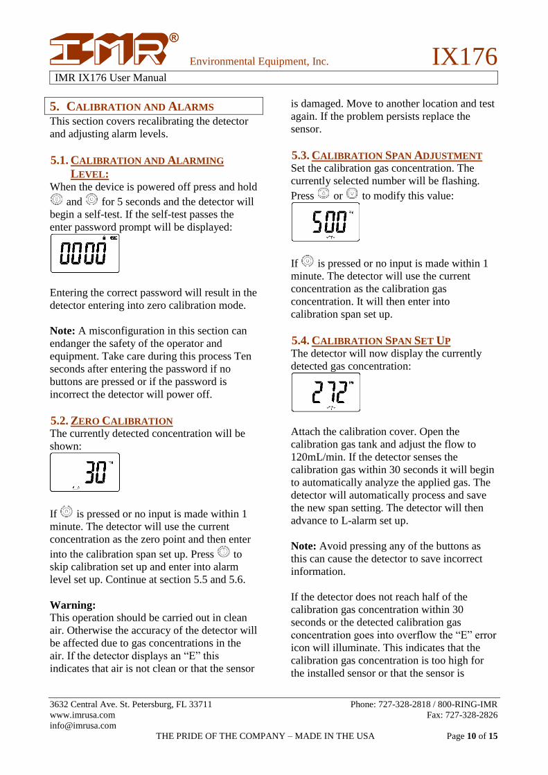
5.3. CALIBRATION SPAN ADJUSTMENT Set the calibration gas concentration. The
currently selected number will be flashing.
Press or to modify this value:
If is pressed or no input is made within 1
minute. The detector will use the current
concentration as the calibration gas
concentration. It will then enter into
calibration span set up.
5.4. CALIBRATION SPAN SET UP The detector will now display the currently
detected gas concentration:
Attach the calibration cover. Open the
calibration gas tank and adjust the flow to
120mL/min. If the detector senses the
calibration gas within 30 seconds it will begin
to automatically analyze the applied gas. The
detector will automatically process and save
the new span setting. The detector will then
advance to L-alarm set up.
Note: Avoid pressing any of the buttons as
this can cause the detector to save incorrect
information.
If the detector does not reach half of the
calibration gas concentration within 30
seconds or the detected calibration gas
concentration goes into overflow the “E” error
icon will illuminate. This indicates that the
calibration gas concentration is too high for
the installed sensor or that the sensor is

Environmental Equipment, Inc. IX176
IMR IX176 User Manual
3632 Central Ave. St. Petersburg, FL 33711 Phone: 727-328-2818 / 800-RING-IMR
www.imrusa.com Fax: 727-328-2826
THE PRIDE OF THE COMPANY – MADE IN THE USA Page 11 of 15
defective. Test again with a lower calibration
gas concentration or replace the sensor of the
issue persists.
Calibration of an O2 sensor will skip section
5.3 and 5.4.
5.5. L-ALARM SET UP Now the L-alarm can be adjusted. The screen
will display the current alarm setting. Press
or to adjust the flashing value as needed
and then press to complete set up.
The detector will then advance to H-alarm set
up.
5.6. H-ALARM SET UP Now the H-alarm can be adjusted. The screen
will display the current alarm setting. Press
or to adjust the flashing value as needed
and then press to complete set up.
The detector will then power off.
6. BATTERY CHARGING If the battery is low or the detector is not being
responsive the battery need to be charged.
Note: The detector cannot be powered on
while it is charging. To avoid fire or explosion
do not charge the detector on site at a
hazardous location. Attempting to charge the
detector while it is powered on will prolong
the time needed to fully charge the device.
7. DATA UPLOAD Connect the detector to a PC with the provided
USB cable. Then open the data software.
Note: Data upload function is only available
only if requested at time of purchase.
8. SENSOR USAGE AND REPLACEMENT The sensors that this detector utilizes are
modularized. It is important to keep track of
the sensors age and replace it every 3 to 5
years depending on sensor type. The device
should be calibrated every 6 months to ensure
best accuracy of the installed sensor.
Sensor replacement should only be done by
IMR or an authorized repair center. In the
event that neither of these options are possible
contact IMR for support. Do not replace the
sensor with unauthorized parts.
9. CARRY CLIP CONFIGURATION The device can have either a belt clip or a
crocodile buckle and ring. See the diagram
below for more information.
1. Crocodile Buckle
2. Ring
3. Mounting hole
4. Belt clip
5. Screw hole

Environmental Equipment, Inc. IX176
IMR IX176 User Manual
3632 Central Ave. St. Petersburg, FL 33711 Phone: 727-328-2818 / 800-RING-IMR
www.imrusa.com Fax: 727-328-2826
THE PRIDE OF THE COMPANY – MADE IN THE USA Page 12 of 15
10. TROUBLESHOOTING GUIDE
Issue Possible Reason Solutions
Unable to power on Low battery Charge for the recommended
duration
Unresponsive Contact IMR
Circuit fault Contact IMR
No response to gas Warm up not finish Wait till it finishes
PCB fault Contact IMR
Testing reading incorrect Sensor overdue for
replacement
Replace the sensor
Calibration out of date Calibrate the sensor
Incorrect time Battery depleted Charge the device and set the
time
Electromagnetic interference Reset the time
Unable to complete a “Zero”
calibration
Sensor drift Calibrate or replace the sensor
It displays “-0” Sensor drift Calibrate or replace the sensor
It displays
Sensor fault Replace the sensor
11. USAGE NOTICE
Avoid intense dropping or shocking.
If using in high concentration gas environments the device will not work normally.
Strictly follow this manual while using the device. Failure to do so will cause incorrect detection
result or damage the device.
It is forbidden to use and store the device in corrosive environments (high concentrations of CL2)
or harsh environments (exceedingly high or low temperature, high humidity, electromagnetic
field, intense sunlight etc.)
After prolonged use if the device is dusty use a clean soft cloth to clean it. Otherwise the surface
may become scratched or damaged.
In order assure detection accuracy the re-calibration period is every 6 months and cannot be more
than 1 year.
Do not discard the battery in the standard trash. Please follow all local regulatory and
environment regulations pertaining to lithium battery disposal.
For any usage or trouble shooting not covered in this manual contact IMR.
Disassembly, modification and repair of the device should be carried out by authorized personnel
only.
It is dangerous to charge the device or upload data to a PC in hazardous environments.

Environmental Equipment, Inc. IX176
IMR IX176 User Manual
3632 Central Ave. St. Petersburg, FL 33711 Phone: 727-328-2818 / 800-RING-IMR
www.imrusa.com Fax: 727-328-2826
THE PRIDE OF THE COMPANY – MADE IN THE USA Page 13 of 15
TARGET GAS LIST Gas Range L-alarm H-alarm TWA STEL
CH4 0-100%LEL 20%LEL 50%LEL
C3H8 0-100%LEL 20%LEL 50%LEL
H2 0-100%LEL 20%LEL 50%LEL
H2 0-1000ppm 35ppm 250 ppm
H2S 0-100ppm 10ppm 15ppm 10ppm 15ppm
CO 0-1000ppm 35ppm 200ppm 35ppm 200ppm
CO 0-2000ppm 35ppm 200ppm 35ppm 200ppm
O2 0-30%vol 19.5%vol 23.5%vol
C2H5OH 0-100%LEL 20%LEL 50%LEL
NH3 0-100ppm 25ppm 50ppm 25ppm 35ppm
CL2 0-20ppm 5ppm 10ppm 0.5ppm 1.0ppm
SO2 0-100ppm 2ppm 5ppm 2ppm 5ppm
Environmental Equipment, Inc. IX176
IMR IX176 User Manual
3632 Central Ave. St. Petersburg, FL 33711 Phone: 727-328-2818 / 800-RING-IMR
www.imrusa.com Fax: 727-328-2826
THE PRIDE OF THE COMPANY – MADE IN THE USA Page 14 of 15
12. WARRANTY IMR Environmental Equipment, Inc. states the following:
IMR‚ as manufacturer hereby grants the following worldwide IMR warranty for an IMR analyzer
purchased from an authorized dealer.
1. The IMR warranty shall entitle every IMR customer to demand a free replacement or repair of
the defective parts from any IMR dealer authorized for the respective IMR unit.
2. The IMR warranty shall be granted on the factory new unit and shall commence on the date of
the delivery of the original IMR unit to the customer.
3. The IMR warranty shall refer to absence of faults with respect to the state of the art nature of the
sold unit in terms of material and finish. The warranty for all parts fitted during the twelve-month
warranty period shall end with the unit warranty.
4. After the establishment of a material or production fault by IMR or the authorized IMR dealer,
the faults will be eliminated by means of free repair or replacement. Replaced parts shall become
the property of IMR.
5. No warranty claims may be made for maintenance and setting work, cleaning or other utility
materials required for the function of the unit and other wear parts unless they have a direct
bearing on work performed under the warranty.
6. The terms and conditions for the acknowledgement of this warranty shall be the presentation of
the fully completed warranty card, which must contain the confirmation from the authorized IMR
dealer on its delivery and, if applicable, the prescribed maintenance work.
7. The IMR warranty shall only be applicable if
7.1. The analyzer has been maintained in accordance with the instructions issued by the
manufacturers and the operating instructions by an authorized IMR dealer.
7.2. Only original IMR spare parts have been used for any repairs.
7.3. The unit has been used properly, the operating instructions observed and the unit has not
been used for a purpose other than the one for which it has been designed.
7.4. The IMR unit has been left in its original design and meets the original IMR specifications.
7.5. The fault is not due to external influences or use for a purpose other than the one for which it
has been designed.
7.6. Exclusively authorized IMR dealers have made repairs to the IMR unit.
7.7. The IMR unit has been sent to an authorized IMR dealer immediately after the fault was
discovered.
8. Warranty time for the analyzer, including electrochemical sensors is 12 months.

Environmental Equipment, Inc. IX176
IMR IX176 User Manual
3632 Central Ave. St. Petersburg, FL 33711 Phone: 727-328-2818 / 800-RING-IMR
www.imrusa.com Fax: 727-328-2826
THE PRIDE OF THE COMPANY – MADE IN THE USA Page 15 of 15
13. CONTACT INFORMATION
Environmental Equipment, Inc.
3632 Central Ave.
St. Petersburg, FL 33711
USA
Phone: 727/328-2818
Fax: 727/328-2826
1800#: 1-800/746-4467
Internet: www.imrusa.com
Email: [email protected]
IMR® is a registered Trademark of IMR® Environmental Equipment, Inc.