Improving Your Energy IQ - The C&S Companies Atoll Camp Parks Sierra Army Depot West Point Oregon...
7
10/27/2015 1 OBG PRESENTS: Microgrids and Distributed Generations from Federal to State Installations Mohammad Nikkhah Mojdehi, PhD AGENDA Microgrid Concept Motivations for Microgrid in DoD Net Zero Initiative SPIDER JCTD Other Microgrid Installations State of Technology Lesson Learned and Challenges Jamestown Microgrid 2 3 Microgrid Concept Microgrid Concept 4 Definition Group of interconnected loads and distributed energy resources within clearly defined electrical boundaries that acts as a single controllable entity with respect to the grid Can connect and disconnect from the grid to enable it to operate in both grid connected and island-mode [1] [1] The U.S. Department of Energy. Microgrid is a group of interconnected loads and distributed energy resources within clearly defined electrical boundaries that act as single controllable entity with respect to the grid. 5 Role Actor Monitoring and Control EMS Historian HMI HMI Server Protection IED Protection Relay Breaker Fuse Generation Generator Generator Controller Automatic Transfer Switch Renewable Energy Generator Renewable Energy Controller Load Building Management System Load Controller Smart Meter Distribution RTU PMU PCC Synchronizing Relay Distribution Transformer Grounding Transformer Disconnect Switch Storage Energy Storage System Energy Storage Controller Plug-in Electric Vehicle Electric Vehicle Supply Equipment Power Actors in the Microgrid Control System [2] [2] C. K. Veitch, J. M. Henry, B. T. Richardson, D. H. Hart, “Microgrid Cyber Security Reference Architecture,” Sandia National Laboratories, Technical Report SAND2013-5472, 2013 6
Transcript of Improving Your Energy IQ - The C&S Companies Atoll Camp Parks Sierra Army Depot West Point Oregon...
10/27/2015
1
OBG PRESENTS:
Microgrids and Distributed Generations from Federal to State Installations
Mohammad Nikkhah Mojdehi, PhD
AGENDAMicrogrid Concept
Motivations for Microgrid in DoD
Net Zero Initiative
SPIDER JCTD
Other Microgrid Installations
State of Technology
Lesson Learned and Challenges
Jamestown Microgrid
2
3
Microgrid Concept
Microgrid Concept
4
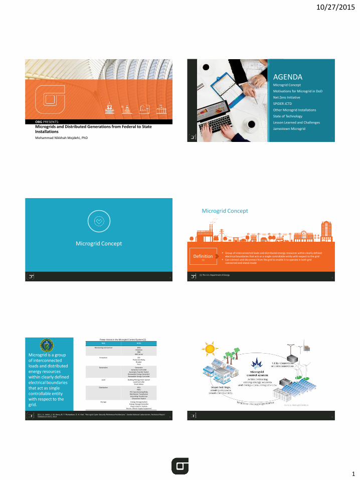
Definition Group of interconnected loads and distributed energy resources within clearly defined
electrical boundaries that acts as a single controllable entity with respect to the grid Can connect and disconnect from the grid to enable it to operate in both grid
connected and island-mode [1]
[1] The U.S. Department of Energy.
Microgrid is a group of interconnected loads and distributed energy resources within clearly defined electrical boundaries that act as single controllable entity with respect to the grid.
5
Role Actor
Monitoring and Control EMSHistorian
HMIHMI Server
Protection IEDProtection Relay
BreakerFuse
Generation GeneratorGenerator Controller
Automatic Transfer SwitchRenewable Energy GeneratorRenewable Energy Controller
Load Building Management SystemLoad Controller
Smart Meter
Distribution RTUPMU
PCC Synchronizing RelayDistribution TransformerGrounding Transformer
Disconnect Switch
Storage Energy Storage SystemEnergy Storage Controller
Plug-in Electric Vehicle Electric Vehicle Supply Equipment
Power Actors in the Microgrid Control System [2]
[2] C. K. Veitch, J. M. Henry, B. T. Richardson, D. H. Hart, “Microgrid Cyber Security Reference Architecture,” Sandia National Laboratories, Technical Report
SAND2013-5472, 2013 6

10/27/2015
2
Microgrid Concept
7
Common Implementation of Microgrid [3]
[3] S. B. Van Broekhoven, N. Judson, S. V. T. Nguyen, and W. D. Ross, “Microgrid study: energy security for DoD installations,” MIT Lincoln Laboratory, Technical Report 1164, 2012.
Stand-alone backup generation
Type 1aStand-alone generation with grid-tied RE generation
Type 1bGrid-tied backup generation that can be islanded
Type 2aGrid-tied backup generation with islandableRE generation
Type 2b
8
Motivations for Microgrid in DoD
Environmental Security and Technology Certification Program (ESTCP)
▪ Established in 1995
▪ DoD’s environmental technology demonstration and validation program
▪ Identify / demonstrate the most promising innovative and cost-effective technologies / methods that address DoD’s high-priority environmental requirements
9
Net Zero Initiative (2010)
Announced by the Army to evaluate the feasibility and implementation of:
▪ Producing as much energy on-site as it uses annually
▪ Limiting the consumption of freshwater resources
▪ Reducing, reusing, & recovering solid waste streams
10
2005 200920072006 2008
EISA 2007 EO 13514EPAct05
Net Zero Initiative
11
Smart Power Infrastructure Demonstration for Energy Reliability and Security (SPIDERS) Joint Capability Technology Demonstration (JCTD) is a $30 million project lead by Sandia National Laboratories, under a partnership between the DoD and the DoE to:
• Protect task critical assets from loss of power due to cyber attack
• Integrate renewable energies to power task critical assets in times of emergency
• Sustain critical operations during prolonged power outages
• Manage efficiency to reduce petroleum demand, carbon bootprint, and cost.
12
Net Zero Initiative

10/27/2015
3
13
In 2008, the U.S. DoD and the U.S. DoE defined a joint initiative to address military energy use by identifying specific actions to reduce energy demand and increase use of renewable energy on DoD installations.
The Net Zero Initiative is a holistic strategy for managing energy, water, and waste at Army installations.
14
▪ Producing as much energy on-site as it uses annually
▪ Limiting the consumption of freshwater resources
▪ Reducing, reusing, and recovering solid waste streams
Energy Net Zero Pilot Installations
Fort Bliss Fort Carson Fort Detrick Fort Hunter
Liggett Kwajalein Atoll Camp Parks Sierra Army Depot West Point Oregon Army
National Guard (state wide)
October 2010
February 2011
April 2011
Net Zero Initiative announced
The Army identifies 17 pilot installations to bring the overall consumption of resources down a rate of zero by 2020
Goals
15
Net Zero Hierarchy
Reduction
Re-Purpose
Recycling & Composting
Energy Recovery
Disposal
ENERGY
[4] Net Zero progress report, Department of Defense, Assistant Secretary of the Army (Installations, Energy and Environment), 2013. 16
Net Zero Energy Hierarchy
Reduction
Re-Purpose
Recycling & Composting
Energy Recovery
Renewable Energy
ENERGY
[4] Net Zero progress report, Department of Defense, Assistant Secretary of the Army (Installations, Energy and Environment), 2013.
Fort Bliss
100% of the electric load and 46% of the thermal load for an overall 78% Net Zero solution
17
Fort Bliss load reduction and renewable energy integration roadmap [4]
[4] Army Net Zero energy roadmap and program summary FY 2013, National Renewable Energy Laboratory.
Wind power Combination of PV and Concentrating Solar Power (CSP) 6 hours energy storage Biomass Ground Source Heat Pump (GSHP) Solar Ventilation Preheating (SVP) Solar Hot Water
18
Fort Carson load reduction and renewable energy integration roadmap [4]
[4] Army Net Zero energy roadmap and program summary FY 2013, National Renewable Energy Laboratory.
Wind power Combination of PV and Concentrating
Solar Power (CSP) 6 hours energy storage Biomass Ground Source Heat Pump (GSHP) Solar Ventilation Preheating (SVP) Solar Hot Water
Challenges: Very low life cycle cost-effectiveness of
renewable energy Mission impacts from renewable
systems A premium for renewables in a budget-
constrained environment; Lack of individual building data and
electrical one-line diagram
Fort Carson
100% of electrical and 93% of thermal energy from renewable systems as an Net Zero solution

10/27/2015
4
19
Fort Detrick load reduction and renewable energy integration roadmap [4]
[4] Army Net Zero energy roadmap and program summary FY 2013, National Renewable Energy Laboratory.
15 MW PV system An incinerator boiler system Central steam plant decommissioning
Challenges: High cost of renewable energy Security of SCADA equipment
Fort Detrick
71% of energy reduction through energy efficiency and renewable energy
20
SPIDERS JCTD
Smart Power Infrastructure Demonstration for Energy Reliability and SecurityJoint Capability Technology Demonstration
2008
Defense Science Board Task Force on DoD Energy Strategy issued the report “More Fight-Less Fuel”
21
Challenges of DoD [5]
22
Unnecessarily high and growing battlespace fuel demand
Dependencies of military installations on vulnerable commercial power grids
[5] “More fight-less fuel,” Report of the Defense Science Board Task Force on DoD Energy Strategy, Office of the Under Secretary of Defense for Acquisition, Technology, and Logistic, 2008, Available: http://www.acq.osd.mil/dsb/reports/ADA477619.pdf.
23
SPIDERS JCTD
Partnership between the DoD and the DoE
Protect task-critical assets
Integrate renewable and other distributed energy generation concepts
Sustain critical operations during prolonged power outages
Manage installation electrical power and consumption efficiency to reduce petroleum demand, carbon boot print, and cost
24
Phase I Joint Base Pearl Harbor-Hickam
Phase II Fort Carson Microgrid project
Phase III Camp Smith Energy Island
Template for DoD-wide implementation Transition to commercial sector Transition cyber security to federal sector
and utilities
10/27/2015
5
25
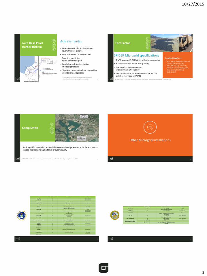
Achievements [6]
▪ Power export to distribution system (over 1MW net export)
▪ Fully loaded black start operation
▪ Seamless paralleling to the commercial grid
▪ Paralleling and synchronization of diesel generators
▪ Significant penetration from renewables during islanded operation
Joint Base Pearl Harbor Hickam
[6] SPIDER Phase 2 Fort Carson technology transition public report, Naval Facilities Engineering Command, 2014. 26
Fort Carson
SPIDER Microgrid specifications▪ 2 MW solar and 3.25 MVA diesel backup generation
▪ 5 Electric Vehicles with V2G Capability
▪ Upgraded control components with communication ability
▪ Dedicated control network between the various switches (provided by IPERC)
[6] SPIDER Phase 2 Fort Carson technology transition public report, Naval Facilities Engineering Command, 2014.
Security Guidelines
NIST 800-82, Guide to Industrial Control System Security
NIST 800-53, App 1 Security Controls, Enhancements, and Supplemental Guidance
DoDI 8500.2
27
A microgrid for the entire campus (15 MW) with diesel generators, solar PV, and energy storage incorporating highest level of cyber security
Camp Smith
[6] SPIDER Phase 2 Fort Carson technology transition public report, Naval Facilities Engineering Command, 2014.28
Other Microgrid Installations
29
Location Microgrid Type DER Technology Purpose
ANG Fargo 2a - demand responseANG ST. Paul 2a - demand response
ANG VOLK Field 2a - demand responseBuckley AFB - diesel generator (1 MW) -Cannon AFB - - -
Cape Canaveral AFS 1a diesel generator island operationClear AFS 1a coal-powered generation -
Creech AFB - - -
Dyess AFB 2a 5 diesel generator (2.2 MW each) peak shaving
Eielson AFB 1aCHP
1.5 MW black start diesel generatorIsland operation
Kirtland AFB - - ESTCP
Kunsan AB 2a 8 diesel generator (750 kW each)demand response island operation
JB San Antonio/Lackland AFB 2bPV
lead-acid batteries-
Maxwell AFB 2a2 backup generator (600 kW)
generator (100 kW)PV (500 kW)
island operation
McConnell AFB 1a 2 diesel generators (1.5 MW each) island operation
JB McGuire-Dix-Lakehurts AFB 2bPV (75 kW)
lithium ion battery (25 kWh)power cell (80 kW)
ESTCP peak shaving demo
Offutt AFB - - -
Osan AB 1a 6 mobile generators (750 kW) island operation
Patrick AFB 1a 2 diesel generators (6.6 MW) -
Robins AFB 2a combustion gas turbine plant (80 MW) island operation
Schriever AFB - - -Stewart AGS 2b PV (250-500 kW) -
Tinker AFB 2a combustion gas turbine plant (80 MW) island operation
US Air Force Academy 2b PV (6 MW) -
Vandenberg AFB 2a 5 generators (3 MW each)peak shaving
island operationWhiteman AFB - - -
30
Location Microgrid Type Generation Technology Purpose
Fort Belvoir 2aCHP (1 MW)
diesel generator (800 kW)ESTCP
Fort Bragg 2a genset (5 MW) Peak shavingFort Devens - - ESTCP
Fort Sill 1b
2 diesel generators (210 kW each)PV (20 kW)
wind (2.4 kW)battery bank (500 kVA)
island operation
Fort Wainwright 1a CHP (20 MW) island operation
Wheeler Army Airfield
1b PV (225 kW) -2b (planned) 2 MW power plant -
2a (planned)bio-fuel compatible reciprocating diesel
(52 MW)-

10/27/2015
6
31
Location Microgrid Type Generation Technology PurposeNSF Dahlgren 2a diesel generators (14 MW) demand responsePMRF Barking 1a diesel generators (1.5 MW) Island operation
Philadelphia Navy Yard - - -
Location Microgrid Type Generation Technology Purpose
MCAGCC Twentynine Palms 2aCHP (7.2 MW)
diesel backup generatorPV (1.3 MW)
island operation
MCAS Miramar 2b (planned)
landfill gas system (3.2 MW)cogen (1 MW)
PV (1 MW)battery (1 MW)
island operation
Location Microgrid Type Generation Technology Purpose
JB Lewis-McChord - - island operation
Pohakuloa Training Area - - -
Joint Bases
32
State of Technology
No current DoD installation microgridshave the degree of integration with the utility grid necessary to participate in the ancillary services market.
No current installation microgrids can island with their intermittent renewable generation.
Dynamic Load shedding is a necessary element to implement an island operation seamlessly and not yet successfully demonstrated.
Multi-dimensional strategies (Energy
Efficiency, Renewable Energy, and etc.)
Utilization of existing technologies
High cost of renewable energies
Private-sector financing through
third-party contracts
Utility interconnection for
DGs IEEE 1547
Cyber security concerns / lack of
standards
Lack of dynamic load shedding
ride through demonstration
Lack of load information/one-line
diagram of feeders
Lessons Learned and Challenges
33
Jamestown Microgrid
34
35
Jamestown Electric Power System
Aggregated hourly thermal and electrical load for 2014
Carson Generation Station
36
The gas turbine can be run in simple cycle, with the heat recovery steam generator, with an efficient operating range between approximately 21.5 and 43 megawatts.
Carson Station Generation Facilities
10/27/2015
7
37
OBG | THERE’S A WAY