Improving the MEP coordination using BIM technologies A...
41
Department of Civil and Environmental Engineering Division of Construction management CHALMERS UNIVERSITY OF TECHNOLOGY Master’s Thesis BOMX02-16-100 Gothenburg, Sweden 2016 Improving the MEP coordination using BIM technologies – A case study based on observations and interviews Master’s Thesis in the Master’s Programme Design and Construction Project Management VAIDAS MOTIEJUNAS
Transcript of Improving the MEP coordination using BIM technologies A...
Department of Civil and Environmental Engineering Division of Construction management CHALMERS UNIVERSITY OF TECHNOLOGY Master’s Thesis BOMX02-16-100 Gothenburg, Sweden 2016
Improving the MEP coordination using BIM technologies –
A case study based on observations and interviews
Master’s Thesis in the Master’s Programme Design and Construction Project Management
VAIDAS MOTIEJUNAS

MASTER’S THESIS BOMX02-16-100
Improving the MEP coordination using BIM
technologies – A case study based on observations and
interviews
Master’s Thesis in the Master’s Programme Design and Construction Project
Management
VAIDAS MOTIEJUNAS
Department of Civil and Environmental Engineering
Division of Construction management
CHALMERS UNIVERSITY OF TECHNOLOGY
Göteborg, Sweden 2016
Improving the MEP coordination using BIM technologies – A case study based on
observations and interviews
Master’s Thesis in the Master’s Programme Design and Construction Project
Management
VAIDAS MOTIEJUNAS
© VAIDAS MOTIEJUNAS, 2016
Examensarbete BOMX02-16-100/ Institutionen för bygg- och miljöteknik,
Chalmers tekniska högskola 2016
Department of Civil and Environmental Engineering
Division of Construction management
Chalmers University of Technology
SE-412 96 Göteborg
Sweden
Telephone: + 46 (0)31-772 1000
Cover:
Beyond the Curve: BIM in Healthcare Moves from Design Phase to the Field
http://www.pagethink.com/v/blog-detail/Beyond-the-Curve-BIM-in-Healthcare-
Moves-from-Design-Phase-to-the-Field/4j/
Printed by Chalmers Reproservice
I
Master’s thesis in the Master’s Programme Design and Construction Project
Management
VAIDAS MOTIEJUNAS
Department of Civil and Environmental Engineering
Division of Construction management
Chalmers University of Technology
ABSTRACT
In the construction industry, the mechanical, electrical and plumbing (MEP) of a facility
can amount to up to sixty percent of its total cost. Considering this number, together
with the challenges of routing each of its systems, the MEP coordination becomes a
high priority in design of constructions. The coordination usually involves the trade
contractors and other contract responsible e.g. engineers, VDC coordinator, to discuss
how to integrate their systems into the building. Traditionally, this process considered
a time demanding overlay of drawings - to identify clashes and route the MEP systems.
With the development of CAD, this process became faster and replaced the traditional
way. Going beyond CAD, BIM technologies brought new processes with clash
detections and high detail visualizations. However, it is yet argued how BIM
technologies should be used as a best approach in the MEP coordination. Therefore, the
purpose of this thesis is to develop a better understanding of how effective MEP team
communication and collaboration can enhance the design coordination, by taking
advantage of BIM technologies. The collection of data was done through two semi-
structured interviews and five observations of the coordination meetings of different
construction projects. The limitations of this thesis consider the two interviews and the
repetitive nature of the observations. The findings suggest that using BIM for MEP is
at an advanced stage, where the coordination is benefiting from clash detection and 3D
visualizations. To improve the coordination several key areas were identified as
important: familiarity with the software, participant commitment, avoiding postponing,
and having present the decision makers during the meetings.
Keywords: Construction industry, CAD, BIM technologies, MEP coordination, clash
detection, 3D visualizations.
II
Förbättring av MEP samordning med hjälp av BIM-teknik
Examensarbete inom Design and Construction Project Management
Design and Construction Project Management
VAIDAS MOTIEJUNAS
Institutionen för bygg- och miljöteknik
Avdelningen för Construction Management
Chalmers tekniska högskola
SAMMANFATTNING
Inom byggbranschen, mekaniska, el och VVS (MEP) av en anläggning kan uppnå till
sextio procent av hela projekt kostnaden. Med hänsyn till detta antal tillsammans med
de utmaningarna blir MEP samordning hög prioritet vid utformningen av
konstruktioner. Samordningen vanligtvis innebär entreprenörer och andra projekt
ansvariga , t.ex. ingenjörer, VDC samordnare för att diskutera hur man kan integrera
sina system i byggnaden. Traditionell process anses vara en tidskrävande lagring av
ritningar för att identifiera kollisioner och leda MEP system. Med utvecklingen av
CAD, denna process blev snabbare och ersatt det traditionella metod. BIM tekniken
medfört nya processer med kollisionskontroll och hög detalj av visualiseringar. Dock,
det är ännu diskussion hur BIM teknik bör användas som en bästa metod i MEP
samordning. Därför, syftet av min examen arbeta är att utveckla en bättre förståelse
för hur effektiv MEP laget kommunikation och samarbete kan förbättra samordningen
projektering, genom att utnyttja BIM teknik. Datainsamlingen gjordes genom två semi-
strukturerade intervjuer och fem observationer av samordningsmöten på olika
byggprojekt. Begränsningarna i denna avhandling anser endast två intervjuer och
repetitiva observationer. Resultaten tyder på att BIM för MEP är ett framskridet stadium
där samordningen gynnas av automatisk kollisionskontroll och 3D-visualiseringar. För
att förbättra samordningen flera nyckelområden var identifierats som viktiga:
förtrogenhet med programmet, deltagare engagemang, undvika att skjuta upp och ha
beslutsfattarna under mötena.
Nyckelord: Construction industry, CAD, BIM technologies, MEP coordination, clash
detection, 3D visualizations.
CHALMERS Civil and Environmental Engineering, Master’s Thesis BOMX02-16-100 III
Contents
ABSTRACT I
SAMMANFATTNING II
CONTENTS III
1 INTRODUCTION 1
1.1 Background 1
1.2 Purpose 2
1.3 Research questions 2
1.4 Limitations 2
1.5 Disposition 3
2 THEORETICAL FRAMEWORK 4
2.1 Building Information Modelling 4
2.1.1 Definition 4
2.1.2 Level of development (LOD) 4
2.1.3 Uses and benefits 5
2.2 MEP coordination process 6
2.2.1 Using BIM for MEP coordination 7
2.2.2 Types of coordination meetings 8
2.2.3 Benefits of using BIM for MEP coordination 10
2.2.4 Recommended best practices 10
2.2.5 BIM and clash detection 11
2.2.6 The BIG Room 12
2.2.7 Common BIM coordination software 13
2.3 Teams in the MEP design coordination 14
2.3.1 MEP coordination and experience 15
3 METHODOLOGY 16
3.1 Literature review 16
3.2 Research Approach 16
3.3 Quantitative and qualitative research 16
3.4 Data Collection 16
3.4.1 Interviews 17
3.4.2 Observations 17
3.4.3 Data analysis 17
3.5 Validity and reliability 18
IV CHALMERS Civil and Environmental Engineering, Master’s Thesis BOMX02-16-100
4 FINDINGS FROM THE OBSERVATIONS & INTERVIEWS 19
4.1 Group observation A 20
4.2 Group observation B 20
4.3 Group observation C 20
4.4 Group observation D 21
4.5 Group observation E 21
4.6 Interview 1 22
4.7 Interview 2 22
5 ANALYSIS AND DISCUSSION 23
5.1 BIM – a step further in the industry 23
5.2 The MEP coordination 24
5.3 Current setting 24
5.4 Work space 25
5.5 Best practice 25
5.6 The research questions answered 26
5.6.1 How can the MEP coordination process be improved using BIM? 26
5.6.2 How should the MEP coordination process be structured and performed?
26
5.6.3 What is the role of the project team in the MEP coordination process?
27
5.6.4 How can the work space improve the MEP coordination? 27
6 CONCLUSION 28
6.1 Future research 29
REFERENCES 29
APPENDIX 31
6.2 Interview questions 31
CHALMERS Civil and Environmental Engineering, Master’s Thesis BOMX02-16-100 V
Preface
The research presented in this thesis was carried out at the Department of Civil and
Environmental Engineering, division of Construction Management at the Design and
Construction Project Management department at Chalmers University of Technology
during January 2015 and June 2016.
I would like to thank everyone who has been involved in this thesis, for support and
encouragement throughout the whole thesis research process. I would like to thank my
supervisor at Chalmers University of Technology, Mikael Johansson, for guidance with
academic issues and support, as well as to all the interviewees, for taking their time and
sharing their valuable information.
Göteborg June 2016
Vaidas Motiejunas

CHALMERS Civil and Environmental Engineering, Master’s Thesis BOMX02-16-100 1
1 Introduction
This chapter presents the background and problem definition of this master
thesis. The purpose and aim will also be presented, followed by objectives,
limitations and the research questions. Also, it includes a disposition of each chapter.
1.1 Background
In the construction industry, the coordination of mechanical, electrical and plumbing
(MEP) systems is a main challenge for complex buildings, mostly due to the
requirements and large number of information exchange among project participants in
the design coordination. Also, with limited budgets and schedules of participants, and
arising technical issues, this process is often slowing down the delivery of projects
(Tatum and Korman, 2000).
Nowadays, the communication among the stakeholders in the design and construction
industry is facilitated by developing digital technologies. As such, Building Information
Modelling (BIM) brings solutions to old problems of multidisciplinary coordination.
One way that BIM supports a better design coordination - is by integrating the analytical
data of each professional service such as HVAC, plumbing, electricity etc. This is done
by identifying the mismatch of information and clashes between the project’s
disciplines, that work together at different project stages. In this regard, BIM has
become more widely used as an efficient process, changing the way the MEP industry
collaborates and coordinates project delivery. This change brings new possibilities in
the industry’s workflow, considered earlier impossible, in terms of: degree of planning,
coordination and communication (Korman et. al., 2010).
Although the BIM approach allows teams to bring data from a range of design
disciplines and to identify potential clashes during the design sessions, there are
remaining challenges during design meetings. Some reasons may be that - project
collaboration and coordination differs from project to project, company to company
with changing project actors, which may have different knowledge areas and even
different agendas. In the context of MEP coordination, these actors may not fully
exploit the capability of BIM to improve project communication, to for example - use
time effectively, to address design issues, to evaluate design configurations and to
implement proposed changes as quickly as possible (Bassanino et al., 2014).
Fernando et al., (2013) argues that advanced collaboration technologies have the
potential to overcome the limitations of current tools used in design reviews. As a result,
project meetings may be more productive by enhancing interaction, brainstorming,
collaboration and reaching consensus. In other words, digital technology has the
potential to create a better understanding of the design between the project actors to
explore the design from various engineering viewpoints. It allows to identify problems
with other disciplines, as well as exploring potential solutions much faster, involving
the whole team. Using an analogy, coordination can be viewed as a team sport where
each participant relies on the deliverables of other team members. Therefore, if one
member is outdated then it affects the whole team’s performance.
2 CHALMERS Civil and Environmental Engineering, Master’s Thesis BOMX02-16-100
1.2 Purpose
As briefly presented, digital tools bring project actors together to solve design
challenges optimizing solutions, reducing the number of meetings, and improving
project delivery through effective project communication.
The purpose of this thesis is to develop a better understanding of how effective MEP
team communication and collaboration can enhance the design coordination, by taking
advantage of BIM technologies. More specifically, it aims to answer four interrelated
questions.
1.3 Research questions
1. How can the MEP coordination process be improved using BIM?
2. How should the MEP coordination process be structured and performed?
3. What is the role of the project team in the MEP coordination process?
4. How can the work space improve the MEP coordination?
1.4 Limitations
This thesis is limited to a number of five group observations involving two
organizations. As well, only two interviews were possible due to time considerations.
It is to be mentioned that the observations following the same organization provided a
rather repetitive process. A view from more organizations regarding the
observations/interviews could have led to a wider perspective pertaining to the thesis’
purpose.
CHALMERS Civil and Environmental Engineering, Master’s Thesis BOMX02-16-100 3
1.5 Disposition
This thesis is structured into five parts, following a typical IMRAD (introduction,
method, results, analysis and discussion) structure, as adapted to its qualitative study.
These five parts are - literature review, methodology, findings, discussion and analysis,
conclusion and future research.
In the Literature review, the concept of Building Information Modelling (BIM) is
presented together with its connection to the MEP coordination. BIM is defined to offer
a comprehensive perspective, as it is in theory, together with its uses and benefits. As
well, the concept of Level of Development (LOD) is attached for a broader
understanding of BIM. The review continues with the presentation of the MEP
coordination, considering both the traditional method, and by using BIM tools.
Additional information such as - common software used, best practices etc. are also
considered. Last in the review, the importance of the project team is discussed in
relation to the MEP coordination.
In the Methodology section it is outlined how this thesis has been carried out, and the
methods of data collection. The concept of a qualitative study with e.g. interviews,
group observations are briefly explained, together with the reliability and validity of
the data.
After the methodology, the Findings section considers the essential parts of information
from the interviews and observations. This is more or less a summarized version
focusing on issues such as: meeting efficiency and participation interaction.
Furthermore, this section aims to support the following analysis and discussion part,
giving extensive data such that information is better captured.
In the Analysis and Discussion section, several major themes were identified aimed to
provide an answer to the research questions. A parallel between theory and findings
presents several points of advancement in the industry as written in ‘BIM a step further
in the industry’. The chapter continues with focus on the MEP coordination process,
where the current setting is compared with theory in order to bring new insights. And,
connected to the previous, the analysis and discussion stops upon what is considered to
be a MEP coordination best practice. Last, each research question is answered
individually.
The last chapter of this thesis - Conclusion and further research, brings an overview of
what has been done, which questions have been and not been answered. It ends with
suggestions for possible future research.
4 CHALMERS Civil and Environmental Engineering, Master’s Thesis BOMX02-16-100
2 Theoretical framework
The chapter includes the theoretical background focusing on two major topics – BIM
and MEP coordination, with their chosen subtopics as presented below.
2.1 Building Information Modelling
2.1.1 Definition
Building Information Modelling (BIM) has become an emerging technology in the
AEC industry. One way of describing BIM is as a digital technology where all
information pertaining to a project is accurately simulated in a virtual model. This
model, called the building information model contains the relevant data to realize a
building, such as building geometry, geographic information, quantities and properties
of building elements, cost estimates, schedules etc. Therefore, the building information
model becomes a one source information that can be used through the whole lifecycle
of a project (Azhar, 2011). Because of this, another way of viewing BIM, is as a process
- as project participants can communicate and collaborate having the model as a
reference. This means that ideas can be easily discussed around the virtual model - as a
visual cue, as same as for identifying problems with e.g. constructability, positioning
and solutions (Kalinichuk, 2015).
It is important to differentiate the building information model from the traditional 3D
models. A building information model is described as parametric, meaning that it
contains interdependent object information as well as the possibility to export, and link
sets of attributes. For example, in a building information model, a wall will contain
information regarding its geometry, material characteristics, quantities etc. where its
modification will be adjusted according to the whole model in e.g. views, plans. The
3D model would have only geometry information where each modification would be
necessary to be updated manually in each section or view (Azhar, 2010).
2.1.2 Level of development (LOD)
The building information model contains a vast amount of information developing
through the various stages of a project. In order to define the richness of data and the
reliability of the 3D model at different stages, the Level of Development (LOD) criteria
can be used. LOD can be seen as the amount of details included in the building
information model, together with an element’s geometry and related information.
Moreover, it can also be a reference point for the project team to know how much they
can rely on the information in the model. For example, it can allow model users to
understand the limitations of the received building model (Latiffi et al., 2015).
According to the BIM guidelines, (2012) there are five levels of LOD - from conceptual
design to facility management. The information in LOD 100 is at a conceptual level
and it can be used for project pre-planning, feasibility study and basic cost estimation.
LOD 200 is associated with design development, where objects have an accurate
quantity, size, shape, location and orientation. At this level, performance analysis for
different building models elements can be done. In addition to the possibilities to the
previous LOD, with LOD 300 scheduling and estimating is possible, together with more
accurate information on quantities, size, shape and location. LOD 300 is associated with
the documentation of a product in the project stages. Also, there could be a ‘in between’
CHALMERS Civil and Environmental Engineering, Master’s Thesis BOMX02-16-100 5
LOD 350, where the model is optimized for design coordination (Latiffi et al., 2015).
At LOD 400, the building information model is suitable for construction and
fabrication. The elements in the model contain information regarding orientation,
fabrication and installation. The last – LOD 500, can be seen as a fully accurate digital
representation of a facility, ready for facility management (BIM guidelines, 2012).
2.1.3 Uses and benefits
BIM can be used throughout the whole life cycle of a project and its benefits are relative
to each project's characteristics. Therefore, its uses can depend on project size,
complexity, stakeholders involved. For example, considering a large research center,
several BIM uses were found beneficial. Visualizations allowed rendering different
models to collaboratively understand the expectancy and needs of the project. Also, 3D
Coordination was an important use for MEP coordination as it reduced time and
requests for information (RFI), ultimately avoiding additional costs. Using this feature,
conflicts, interferences and collision detection could be automatically checked for
interferences. For example, the software displays elements such as pipes that intersect
with steel beams, ducts, walls etc. Not at least, the BIM model used for facility
management for further renovations, space planning, maintenance works. Construction
planning using BIM led to avoiding schedule delays and costs during construction
(Olsson et al., 2007).
Another example, in the case of a $46 million commercial facility, it has been estimated
a cost benefit of $200,000 attributed to the elimination of clashes as well as a shorter
term with 1,143 hours saved (Dikbas & Akkoyunlu, 2014). According to Azhar, (2011)
similar benefits of cost savings and reduced time were registered on several projects in
the US. On a larger study, analyzing the use of BIM on 32 major projects, Stanford
University’s Center for Integrated Facilities Engineering (Azhar, 2011) reported the
following benefits:
up to 40% elimination of unbudgeted change;
cost estimation accuracy within 3% as compared to traditional estimates;
up to 80% reduction in time taken to generate a cost estimate;
savings of up to 10% of the contract value through clash detections
up to 7% reduction in project time.
CHALMERS Civil and Environmental Engineering, Master’s Thesis BOMX02-16-100
6
2.2 MEP coordination process
MEP is the acronym for the mechanical, electrical and plumbing systems of a building,
that regulate the internal environment such as energy distribution, waste transmission,
fire protection etc. The MEP coordination is referred by building professionals as a
process to fit all these systems into the building structure, where the different trades
integrate their drawings to detect and eliminate spatial and functional interferences.
Speciality contractors must assure that these systems are in compliance with design,
construction and operations criteria (Korman et. al., 2010).
MEP coordination starts when the design and preliminary routing is finished by
engineers. This means that MEP systems components e.g. HVAC duct, pipe, are sized
and represented into diagrammatic drawings. Speciality contractors meet then to
discuss their own design and drawings, and the routing of each system to produce the
schematic design drawings. Based on those, it is the speciality contractor's
responsibility to create detailed drawings. These drawings are called fabrication or shop
drawings, and show how to fabricate and install a particular system (Korman et. al.,
2010).
An often used practice for coordination meetings is where speciality contractors sequent
overlay and compare their drawings on a light table, to identify interferences. In this
process, each speciality contractor comes with the drawing and indicates the preferred
path of their system to function properly. This process is often referred to as - routing
the building systems (Korman et. al. 2010). Also, conflicts are highlighted on the
transparent drawings to be addressed before fabrication and installation. The systems
which pose specific design constraints are prioritized but typically the order is HVAC
duct, chilled and water piping, plumbing, electrical and fire protection etc. These also
need to consider the architectural and structural constraints of the building. Due to
complexity, it is often necessary to prepare separate section views for highly congested
areas. The overlay and comparison process goes until interferences are solved (Korman
et. al. 2010). However, this process is rather time consuming and poses a number of
challenges. Some of these are presented by Olofsson et al., (2007) as being:
difficulty in identifying conflicts due to 2D drawings;
delays due to conflicts identified in the field;
rework to fix conflicts;
increased site supervision;
increased administrative support for information and order changes on
identification of conflicts;
overall reduced productivity for project members;
As MEP systems can amount up to 60 per cent of the building cost, the coordination
needs to consider how to solve these challenge, especially in the case of complex
buildings. From a different perspective, Korman et. al. (2010) points out three typical
problems with MEP coordination in the delivery of projects. First - fragmentation
between design and construction, second - different contractors use different
technologies, and third - not using a building model throughout the lifecycle of a
facility.
CHALMERS Civil and Environmental Engineering, Master’s Thesis BOMX02-16-100 7
2.2.1 Using BIM for MEP coordination
Using BIM software for the coordination allows speciality contractors to integrate their
drawings into a single MEP model, making it easier to detect clashes and check design
criteria. Such software can be Navisworks for clash detection, ArchiCAD for creating
and importing 2D and 3D drawings, Autodesk Revit etc. (Korman et. al. 2010).
Using BIM for coordination, allows speciality contractors to define their requirements
and goals during the model creation. As such, BIM facilitates dialogue to discuss
directly the sequence and constructability of systems, having the model as a point of
reference (Korman et. al. 2010). A framework of MEP coordination using BIM is
suggested by Lv & Liang (2014). This can be structured in three phases. In a first phase,
each MEP model is created separately and further integrated into a MEP model. The
second phase is integrating the MEP model with the building structure BIM model,
followed by error and collision checks. In the last phase, the design team performs full
collision checks and takes notes.
Following a more detailed approach to the coordination process using BIM, Khanzode
et. al., (2007) summarizes the keys aspects learned from successfully delivering a large
medical facility.
1. Defined role of participants in the MEP coordination
It is important that the general contractor (GC) is facilitating the MEP coordination
process. In this role, the GC is to create a detailed schedule together with the architects,
engineers and subcontractors to support the construction schedule. Once done, a MEP
coordinator from the GC sets milestones together with the detailers. The milestones can
be assigned with for example - using the Last Planner System.
Considering the speciality contractors, they have the responsibility of using VDC/BIM
tools for MEP coordination. Here, the HVAC contractor is best suited to take a lead
role in the coordination, due to the priority of equipment. As an example: VAV boxes,
fire smoke dampers, duct shafts, pressure ducts etc., equipment which take up most
space in the above-ceiling space. Also, it is argued that other speciality contractors e.g.
for plumbing, electrical, fire sprinklers would like to know how the HVAC have routed
their equipment, to guide their own utilities. It is also argued that the type of contract
such as - Design Build, brings an important advantage as the speciality contractors
come early in the project i.e. in between conceptual and schematic design phases. This
allows an efficient and a necessary communication to route the building’s utilities.
2. Defining LOD in the working models.
The working models could be architectural, structural and MEP. Khanzode, (2010)
argues the importance of the project team to clearly specify what to model in 3D. For
MEP, the coordination can be divided into the coordination of underground utilities e.g.
plumbing and electrical or above-ceiling coordination of all MEP utilities. The choice
of using 3D tools for modelling these may put different requirements e.g. elements such
as foundations and framing to be required also in 3D.
According to Khanzode et. al. (2007), to use VDC tools for MEP coordination, a
number of 3D models are needed, some of them being and containing:
architectural and structural elements e.g. interior walls, ceiling, structural
framing, slabs, foundations.
mechanical systems e.g. duct work;
plumbing systems e.g. hot and cold water piping;
electrical systems e.g. conduits and cable trays;
fire protection systems;
8 CHALMERS Civil and Environmental Engineering, Master’s Thesis BOMX02-16-100
other systems depending on the project.
3. The coordination process
In a complex project, it is probable that 3D models will be used, where speciality
contractors will create their own. Therefore, it is important that the whole project team
address the technical logistics and specific issues. These could be:
3D models - with descriptive word text e.g. of revisions;
3D models posted on a common platform to be accessed e.g. website, document
collaboration;
everyone works on the same server, which is updated daily;
the insertion point for drawings is at 0,0,0 established in the architectural model.
The coordination process should be started by an initial kick-off meeting where team
members such as - architect, GC, subcontractors, agree on several issues. These could
be technical, logistics as previously described, and space allocation for trade contractors
to work and establishing isolated works e.g. floor plans, such that the coordination goes
in small batches.
As mention by Khanzode et. al. (2010), an efficient sequence of work can include the
following steps:
start with the 3D and architectural model;
add steel details to the model;
do preliminary space allocation;
identify constraints e.g. space;
draw different details e.g. pressure ducts, plumbing lines, sprinkler mains, cold
and hot water mains, lighting and plumbing fixtures;
thereafter perform routing e.g. smaller ducts and flex duct around utilities drawn
before;
2.2.2 Types of coordination meetings
The coordination approach can be decided based on several factors such as - complexity
of the project, project zones, cloud based-based tools, expertise of team members with
the tools. Based on this criteria, Yarmohammadi & Ashuri (2015) specifies five specific
MEP coordination approaches:
Regular coordination - it involves a one day of coordination and four days of design
and modelling per week. Models are integrated and analyzed weekly during the
sessions. The clash detected is assigned to each trade to find resolutions. The modified
models are submitted and revised for the next coordination session.
Parallel coordination - considers that the project is divided into different zone where a
team is assigned to coordinate. Multiple teams work together on coordination tasks.
Coordination conducted by speciality trades: Speciality trades have the responsibility
for coordination where the general contractor intervenes only when major design
modifications are necessary.
Remote coordination - it is used when project members are located in distant places.
Participants engage in a virtual environment to perform the coordination.
Cloud computing-based coordination - this type of coordination allows participants to
access virtual models anytime from anywhere. Coordination clashes can be some
solved almost in real-time using cloud-based products.
CHALMERS Civil and Environmental Engineering, Master’s Thesis BOMX02-16-100 9
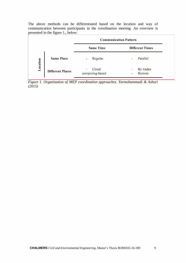
The above methods can be differentiated based on the location and way of
communication between participants in the coordination meeting. An overview is
presented in the figure 1., below:
Figure 1. Organisation of MEP coordination approaches. Yarmohammadi & Ashuri
(2015)
10 CHALMERS Civil and Environmental Engineering, Master’s Thesis BOMX02-16-100
2.2.3 Benefits of using BIM for MEP coordination
Using BIM/VDC tools for MEP coordination can benefit all parties involved in a
project. Some of these are recorded in a study by Olsson et al., 2007 on a complex
healthcare facility:
fewer field conflict and construction related issues (2 of the 233 request of
information processing), where typical were around 200-300 range on similar
projects;
no order changes due to field conflicts, where typically would be 1%-2% of cost of
MEP systems;
accurate remaining model for facility management which makes it easier with the
extraction of information;
for the general contractor not having to spend time on solving field conflict issues
saved around 2-3 hours each day, this compared with similar projects;
architects and engineers spent less time on construction administration issues, with
almost no field conflict issues;
significant fewer injuries recorded - just one for a total work of 203 hours. This
mainly attributed to a better workflow by using the 3D/4D models;
the speciality contractors solved issues much earlier, avoiding problems that usually
are discovered in the field. By comparing the estimated and field productivity, an
estimated improvement of 5 to 25% was realized. This allowed some speciality
contractors to finish their work ahead of the schedule;
by using the 3D models for coordination, the mechanical engineer performed only
40 out of the estimated 25 thousands hour of field work.
In surveying both management and field professionals - Kent, (2014) found that the
main advantage of using BIM is with the coordination and clash detection,
prefabrication. These are attributed to field efficiency, resolved issues and ultimately
saved time and cost.
2.2.4 Recommended best practices
Learning from several projects and years of experience of professionals, a set of
recommended best practices for the MEP coordination can be given. First and foremost,
emphasis is to be put on understanding requirements and establishing program
objectives divided in specifications. From here, these are ultimately translated in first
concept proposals and preliminary budgets. It is recommended that engineers visit the
work site to understand and ensure the constructability of the conceptual design. 3D
models are to be developed in the design development phase, by knowledgeable BIM
engineers or architects. The MEP coordination is performed during the construction
documents phase, where models are combined into a single integrated one. Thereafter,
the model is analyzed subsequently to identify and solve interferences. This leading to
shop drawings for fabrication and the installation of building system. Further steps
include cost estimation, bidding etc. Following this approach, divided into project
phases, a set of best practice is given by Yarmohammadi & Ashuri (2015).
CHALMERS Civil and Environmental Engineering, Master’s Thesis BOMX02-16-100 11
Schematic design
set a detailed workflow for the coordination process;
clarify roles and responsibilities for the GC and trades;
break down the project into smaller sub units and priorities;
describe how detailed the model should be;
avoid interoperability issues by using the same software platform.
Design development
invest in detailed BIM models - higher LOD allows to address a wider range of
conflicts;
assure the modellers/engineers have the necessary expertise and are familiar
with the used codes;
initiate the coordination by trades with larger components moving dependently.
Construction documents
identify high priority clashes before meetings;
categorize clashes into clash batches;
document discussions, ideas and solutions during the coordination meetings;
regular meetings e.g. weekly, bi-weekly to review issues that require immediate
attention;
for quantity take-off ensure the accuracy of the 3D models and drawings.
Construction administration
check the constructability of the shop drawing;
ensure access to most updated models;
organize report changes and RFIs.
2.2.5 BIM and clash detection
The BIM model can be used to determine if MEP components interfere e.g. the
structural system of a building. Another example could simply be the overlying of a
heating duct within the model with the fire extinguishing system. Since, they cannot
occupy the same space, this obviously constitutes a clash. Although straightforward,
this is not always the case. According to Tommelein & Gholami (2012), it is often that
same system components clashes can be ignored when there is one person responsible
to work with those. On the other hand, clashes involving several parties and system
components require inter-disciplinary coordination and discussion.
The term clash may be used to describe more than a simple spatial conflict in the BIM
model. Three categories of clashes can be used: hard clashes, soft clashes and time
clashes. A hard clash refers to any building component(s) penetrating unintentionally
another building component(s). These may be caused by design uncertainty, meaning
that the designer could add and leave components to be determined later, allocating or
not enough space. Also, another reason could be design complexity, typically in areas
where design rules cannot be articulated. In this case, team members may intentionally
leave clashes to occur, e.g. when building systems are subjected to change, to show
design intent. Another reason could be design errors, where the dimension or location
of certain elements is not as intended.
A soft clash, also known as a clearance clash, reference to components which are close,
at a minimum distance, often millimeters apart. Soft clashes may occur due to space
surrounding the physical volume occupied by an object. This happens when an object
12 CHALMERS Civil and Environmental Engineering, Master’s Thesis BOMX02-16-100
is modelled at a LOD without exact details e.g. a valve may be represented using a
conical shape, rather than its precise detailed handle on a stem. Moreover, components
may be close to each other, that their spacing doesn't allow access for placement,
maintenance or application of materials.
A time clash refers to components that may occupy the same physical space,
anticipating the constructability and operability of a facility. One way to anticipate time
clashes is by construction sequencing. This can be done by identifying Priority Walls,
where these full-height walls get work sequence priority over mechanical contractors.
It allows framing and drywall contractors first access to the framing studs to install the
drywall, otherwise blocked if ductwork were to be installed first (Tommelein &
Gholami, 2012).
2.2.6 The BIG Room
The coordination process involves the input of the speciality contractors as it requires
information exchange for routing the MEP systems. Therefore, the coordination is
many times an interdependent process. As an example, a plumbing detailer may want
to find out the placement of waste and vent shafts from the design team, or duct pipes
from the mechanical subcontractor. This request for information may take even days to
be answered when the contractors are working in different projects, hence prolonging
the overall project delivery. Using a setting such as the Big Room reduces the waiting
time for requests for information, as participants can directly get their answers by just
turning one to another.
According to Olsson et al., 2007, a collaborative work environment benefits the MEP
coordination. Such an example is the mentioned and so called 'Big Room'. The Big
Room is often described as an on-site facility which can accommodate the entire project
team for collaborative work. One of the biggest advantages is the direct communication
between participants, in this way avoiding delays with decisions or requests for
information. Moreover, it supports a better team integration through actual presence
and time spent together on project tasks, as well as creating a trust environment. On the
other hand, it relies that all project participants are present during meetings, which could
be difficult especially when trade contractors are involved in several projects. Due to
its collaborative design, it is usually adopted with medium to big projects using BIM
tools, and a design build or integrated project delivery (Dave et. al., 2015).
Complex projects such as medical and pharmaceutical facilities require a large array of
project participants with different trades. Such that the coordination of 20 firms on a
single project can be a challenging task. Olsson et. al., (2007) argues that this approach
shortens the overall time for modelling and coordination, as the information flow is
faster e.g. detailers don't have to wait to see what others are doing. Basically, team
members can actually turn one to another to get answers, and not wait for requests of
information of members which may be in a different city or time zone. The integrated
way of working together with BIM has a great advantage with the 3D and 4D
visualizations, as it is easier for members to have a common reference and to make sure
they mean the same thing. Another important aspect mentioned by Olsson et. al., (2007)
is that the team environment creates a sense of urgency and priority to what team
members are doing at that moment. This, together with an integrated environment leads
to better decisions for the project’s goals, not only short term benefits for each
individual organization.
CHALMERS Civil and Environmental Engineering, Master’s Thesis BOMX02-16-100 13
2.2.7 Common BIM coordination software
In a project it is common that project participants such as speciality contractors and the
general contractor will use different BIM software. Some of these, among the most
common for coordination are Navisworks and Solibri Model Checker.
Navisworks
Navisworks project review software provides a complete suite for the AEC
professionals to integrate their models and data and to holistically review it. In this way,
project stakeholders gain better control over project outcomes, by integrating, analyzing
and communicating to coordinate disciplines, resolve conflicts, plan projects etc.
(Navisworks project review, 2015).
Solibri Model Checker
Especially used for coordination is the Solibri Model Checker. This software analyses
building information models with architectural and engineering designs for their
integrity, quality and physical safety. The software provides also functions such as
information take out from the BIM models. Solibri Model Checker aims for zero design
errors, minimizing costs and supporting a more effective modelling and quality. The
easiness of use makes it convenient for construction professionals, as with simple
clicks, building information models are analyzed and reveal potential flaws in the
design, such as clashing components. Moreover, it checks the model according to BIM
requirements. Other advantages are given by visualization, model walkthroughs,
interference detection and model comparison (Graphisoft, 2015).
14 CHALMERS Civil and Environmental Engineering, Master’s Thesis BOMX02-16-100
2.3 Teams in the MEP design coordination
As much as BIM tools provides all over benefits, often the implementation of these
tools is a considerable challenge. Cidik et al. (2013) argues that in using BIM tools, it
is often given less importance to the human aspect, here referring to the openness of
people to use a technology. This stands especially important for MEP coordination
where a variety of building professionals are involved. Several interviews of building
professionals led to a general opinion that the use of BIM as a design coordination
platform is its interoperability (Cidik et al., 2013). First and foremost, people need to
make sense of the importance of using the IT technology such as BIM, and according
to, this is difficult since older processes are supported by years of experience.
Therefore, professionals go with what worked previously for them. For example, in a
study done by Cidik et al., (2013), mechanical engineers claimed that 3D modelling
would take much time for entering all the details, whereas pen and paper is part of a
creative and collaborative process.
Whatsoever, examples of successfully using BIM for MEP (Lee, 2015 and Olsson et.
al., 2017) show that an important criterion are people, here referring to the project team.
Olsson et. al., (2007) pointed out that clarifying roles should be a starting point before
entering the project, respectively for the MEP design and coordination. An example of
successfully delivering a medical facility using BIM for MEP coordination is given by
Olsson et. al., (2007) where the general contractor took the role of the facilitator
between architects, engineers and subcontractors. This involved handing off
information between parties, together with modelling and coordination. The speciality
contractors had as an initial requirement to work using 3D tools. A large part of MEP
design, for subcontractors e.g. plumbing, electrical, sprinklers were dependent on the
HVAC contractor to see how the equipment will be placed. Due to the earlier
involvement of subcontractors, inputs in terms of constructability and operations could
be discussed. Therefore, providing structure and clarity of the roles is one way to
address the people component in the MEP coordination.
Moreover, looking at some of the factors that affect the team’s productivity with MEP
coordination, Yarmohammadi et. al., (2015) found the following as important:
BIM knowledge of the team - consequently those who had experience with BIM
are more productive;
MEP system complexity - research labs and hospitals will have more demanding
coordination efforts than regular buildings;
Interoperability issues - another factor that weighs in the coordination efforts, since
different contractors will use different applications;
Project location - distant remote locations may face lack of available skilled
workers;
Availability to software coordination for all participants;
Team experience level.
Among these, MEP system complexity, preliminary design quality and team experience
level ranked among the highest in importance (Yarmohammadi et. al., 2015). Also, the
first two rely ultimately on the team experience level, since the coordination effort
requires extensive expertise on routing, clash resolution, familiarity with building codes
etc. And this is further illustrated below, where the comparison between experienced
vs. novice coordinators was measured.
CHALMERS Civil and Environmental Engineering, Master’s Thesis BOMX02-16-100 15
2.3.1 MEP coordination and experience
The position of the MEP coordinator can be taken by a number of professionals such
as BIM/VDC manager, project manager or a project engineer, among others. In this
role the coordinator is responsible for several tasks such as identifying clashes in an
integrated model, preparing clash reports, suggesting solutions, leading the meeting and
documenting actions taken (Yarmohammadi et. al., 2015).
The question of experience in performing coordination was posed by Yarmohammadi
et. al., (2015). Experienced professionals with for example +3 years, and novice
professionals were observed in several coordination tasks to see what importance
experience has in the coordination process. Among the coordination tasks, those that
showed significant difference between the categories, were the ability to retrieve data,
analyses it and understanding its context and causes. In retrieving data, it was observed
that experienced professionals tended to get more information from the model e.g.
object type, system type, spatial information, routing compared to novices e.g. mostly
spatial information. Exemplified in a clash scenario, the number of information items
retrieved was half for novice compared with experts. This is explained to be because,
novices were not very familiar on how to locate the information as well as with the
model navigation.
In analyzing the information - analyzing the context refers to that context around the
surrounding environment of a clash. Here it was notices that experienced coordinators
tended to spend more time on navigating the model, in understanding the context. In a
second step, analyzing the cause and severity, it showed that experienced coordinators
could evaluate better e.g. the congestion of an area, complexity of the designed system
and its impact on the surrounding. This kind of feedback suggests that knowledge
gained through experience will, on a cumulative level, lead to a more efficient
coordination (Yarmohammadi et. al., 2015).
16 CHALMERS Civil and Environmental Engineering, Master’s Thesis BOMX02-16-100
3 Methodology
The chapter presents the work process of this thesis and explains the research design
and how data was gathered.
3.1 Literature review
A literature review can be simply viewed as a process of studying what was written on
a particular topic. In qualitative research, a literature review is considered an iterative
process as new questions and concepts are arising. The purpose of the review is to build
the theoretical knowledge to support arguments around the studied topic.
As such for this master thesis, the literature review was done considering mostly using
sources such as scientific articles and websites. These were found using keywords such
as BIM and MEP coordination, design meetings and MEP etc. on search engines such
as Chalmers’ library and google scholar.
3.2 Research Approach
The research approach of this master thesis is based on group observations and
qualitative interviews. A research approach is the plan and procedures for the research
project involving the collection, analysis and interpretation of data (Creswell, J.W.,
2009). The two main approaches are quantitative and qualitative research.
3.3 Quantitative and qualitative research
Creswell, J.W., (2009) views a qualitative research as the exploration and
understanding of a meaning of a social or a human problem, involving individuals and
groups. The process of a qualitative research starts by creating a number of themes and
questions through which the data is collected. This is done through a set of questions to
guide the interview, allowing flexibility in the sequence of questioning as new ideas
emerge. Often the interview is done in the participant’s setting.
A quantitative research is a different approach compared with the qualitative one. A
quantitative research is rather based on measurements and statistics of certain variables
and, or their relationship. Moreover, it considers a larger batch of samples with a
structured interview format as a questionnaire. Unlike the qualitative approach, the
quantitative relies on what the numbers say rather than individual, or group
interpretations.
3.4 Data Collection
The collection of data for this master thesis was done through observations and semi-
structured interviews, as well as from similar sources. According to Heopfl, (1997),
there can be primary and secondary data sources. Primary data concern the information
collected through interviews, observations or other direct sources. Secondary data
refers to the data has been already collected for a given study, having a similar focus or
purpose as the researched one.
CHALMERS Civil and Environmental Engineering, Master’s Thesis BOMX02-16-100 17
3.4.1 Interviews
A total of two semi-structured interviews were conducted for this master thesis.
According to Heopfl, (1997), qualitative interviews can either be informal such as
conversational interviews, semi-structured interviews and standardized, open-ended
interviews.
For the semi-structured interview, a guide comprising a list of questions or general
questions can be used, according to the interviewer's focus. The interview guide serves
as a structure for the interviewing time, a systematic approach of questions or time as
well as keeping the interaction focused. One of the premises of qualitative research is
that the data should be reproducible in similar circumstances. Yet, as new ideas emerge,
the interviewer has the flexibility to modify the interview guide to focus on areas of
particular importance or to exclude chosen questions.
In recording data one may use the conventional note taking or using a tape recorder.
According to Heopfl, (1997) - using a tape recorder has the advantage to capture a vast
amount of data which can the researcher analyses, compared to hurried note taking. As
such, for this master thesis a recording device was used.
3.4.2 Observations
Data collected through observations is one of the most common in field research. This
is used with the purpose of describing settings involving activities, people and their
meaning, while being observed. Compared to interviews, observations allow a deeper
understanding of the context of an event, and allow the observer to see things that the
participants are unaware. Through an observation, one may monitor both verbal and
nonverbal cues according to the research's aim. Several strategies can be used according
to Heopfl, (1997). In one case, the researcher can watch without being observed. A
second case can be when the observer has a passive presence, not interacting with the
participants. A third case may consider the observer with limited interaction with
participants, intervening only with the purpose of receiving a clarification of an action.
A last case is when the observer considers an active presence, as a full participation
with hidden or known identify.
Recording data in observation relies on the use of field notes. These may include
descriptions of settings, people, activities and sounds. When possible, the researcher
may use photographs, videotapes or audiotapes to accurately reconstruct the setting of
the observation. In other cases, it is common to make drawings or maps to serve as a
visual aid. Due to the vast amount of information, it is recommended that notes are
jotted together immediately after the observation to construct the full field notes
(Heopfl, 1997).
Relying on the theory by Heopfl, (1997) group observations were made in the
participants’ setting where the observer had no intervention, yet participants
acknowledge his physical presence. The note taking was taken in large bites and
afterwards, full field notes were made. Due to the character of the observed meetings,
it was not possible to record using devices as it would may have disturbed the
participants’ setting.
3.4.3 Data analysis
The data analysis begins with identifying emerging themes from the raw data. This
process is often referred as open coding and it involves grouping similar words, phrases,
events into categories. These can be modified or replaced as the data is subsequently
18 CHALMERS Civil and Environmental Engineering, Master’s Thesis BOMX02-16-100
analyzed. Heopfl, (1997) argues that the researcher may also choose a structure
according to their speakers and context. Also, the use of 'voice' in the qualitative report
may be incorporated through participant quotes.
The next stage involves re-examination of the categories to see how they are linked,
process referred to as 'axial coding'. The role with axial coding is to combine the earlier
categories in such a way that it forms a broader ‘picture’. As such, the researcher
attempts to build a conceptual model and determine if sufficient data is available for
interpretation. At a next stage, the researcher must amount together the conceptual
model in a way accessible by its readers, approximating the reality that it represents.
The method of open coding was used to analyses the data from observations, choosing
a structure that follows the context of each individual meeting, as mentioned by Heopfl,
(1997). This is done to provide a clear structure, easy understandable to the reader.
3.5 Validity and reliability
Broadly, validity can be seen as the ability to generalize the findings across different
settings. As well, it should, to some extent accurately describe reality. Validity is
directly connected with credibility which relies on the sample size, richness of data and
the analytical abilities of the researcher. Moreover, credibility can be enhanced by
different triangulation methods - of theory, data and analysis. This involves using a
number of sources that state a similar approach. Another way to add to a report's
credibility is by providing the raw data or the use of member checks, where respondents
corroborate findings.
Reliability can be seen as the degree to which a measurement, given repeatedly, remains
the same, over a given period of time. According to Lincoln and Guba (1985) in Heopfl,
(19970 - ' there can be no validity without reliability and vice-versa - thus a
demonstration of the former is sufficient to establish the latter'.
Validity and reliability in this master thesis is given by the five group observations and
the semi-structured interviews, all of which in a formal, and natural setting of the
interviewee, and those being observed. The large amount of data generated from
observations provide a large sample size for the analysis. Moreover, the triangulation
of theory was used where possible, where three of more sources supported a similar
statement.
CHALMERS Civil and Environmental Engineering, Master’s Thesis BOMX02-16-100 19
4 Findings from the observations & interviews
Five group observations at design meetings were carried out in this study. These were
done in different locations e.g. at the construction site meeting rooms, according to the
project’s location. Out of the five group observations, two represented different
construction companies, mostly with their market in the Nordic region. Observations
A, B and C represent company 1 and observation D represents company 2. The
observed meetings were design review, with the purpose of clash detections. During
these meetings, it was observed the interaction between MEP project participants, VDC
coordinator as well as the meeting efficiency. An individual summary of each of the
meetings is presented below, consisting the empirical result of this study.
4.1 Group observation A
The aim of the meeting is architectural, structural and MEP models collisions control
review. The MEP coordination meeting is hold at the construction site’s office A. The
participants consisted of eight designers for the architectural, electrical, mechanical and
water supply sprinkler systems and one BIM coordinator from the contractor’s side.
The project participants knew that they were observed with the purpose of a research
study.
The collision control report review meeting begins at 8:00 am and is divided into two
stages. The first stage is the architectural and structural parts collision control, followed
by a second stage - of MEP systems.
The meeting takes place in the big meeting room dedicated to the project and it is
equipped with various tools such as a large whiteboard on the wall, project schedules,
last planner system, a projector and tables. The meeting room is ideal and designed to
fit all the construction project designers simultaneously.
For reviewing clashes between building system components and solving them, the
coordination software Solibri Model Checker was used. This appeared to be familiar
for all project participants.
In the first part of the meeting, the BIM Coordinator presented shortly the agenda and
started to go through the updated 3D model - starting from the project’s ground floor
and moving gradually higher, up to the roof. During this step, conflicts and issues
between different systems were identified. Moreover, designers reviewed the possible
issue solutions, considering options, whereas the coordinator marked the issue, and took
a snapshot.
In the second part, MEP designers were not prepared and at times disengaged, this
leading to a poor discussion in resolving MEP conflicts. After some time, the electrical
designer left the meeting room, and later other designers. The BIM coordinator was
navigating the 3D model only, while the MEP coordination process was unstructured.
Moreover, participants in the meeting were using their computers and brought their own
drawings. The meeting was not protocoled and each project participant had been taking
notes in their notebook or on their paper drawings. The meeting ended at 12:00 and
lasted 4 hours.
20 CHALMERS Civil and Environmental Engineering, Master’s Thesis BOMX02-16-100
4.2 Group observation B
The aim of the meeting is architectural, structural and MEP models collisions review,
and it is hold at the construction site’s office B. A total of seven participants took part,
representing subcontractors for architectural, electrical, mechanical, water supply
systems, and a BIM coordinator from the contractor’s side. As in the previous
observation, the participants were informed that they were observed for a research
project.
Being part of the same company, the format of the meeting is similar to group
observation A, involving equipment such as whiteboard, projector, tables etc. The BIM
coordinator presented briefly the agenda and started to navigate through the 3D model,
this time - top to bottom e.g. roof to basement premises. At each floor conflicts and
issues are reviewed. As these were identified, the designers considered possible
solutions, options and took notes and snap-shots. At the end of the meeting, the BIM
coordinator went through all the collisions again, reminding the remaining ones to be
solved.
During the meeting, it was observed that the project participants were actively
collaborating e.g. discussing several alternatives of issues. Constructive inputs were
noticed especially from the architect.
The VDC coordinator used Solibri Model Checker to navigate, take notes, snapshots
etc. Participants were using their own computers throughout the meetings, taking notes
electronically and on their paper drawings.
The meeting took 3 hours, from 9:00 to 12:00 and it was not protocoled.
4.3 Group observation C
This observation considered the same company, project and setting for the coordination
meeting as observation A. Representatives from architectural, electrical, mechanical,
water supply sprinkler systems were present. The BIM coordinator was leading the
meeting.
The coordination meeting started in a similar manner as its first observation. It is
divided into two stages, the first for the checking the collision between architecture and
structural elements and the second stage is between MEP systems. The BIM coordinator
starts with presenting the agenda and what needs to be addressed. Afterwards, he goes
through the updated model from the ground floor up to the roof. In this process, the
group observation C involved the same project and location as observation A.
A common observation was that the communication between participants was less
efficient, even if all were actively participating. This meaning that some previous issues
could not be solved and needed further postponing. The project complexity was high.
CHALMERS Civil and Environmental Engineering, Master’s Thesis BOMX02-16-100 21
4.4 Group observation D
The aim of the meeting is architectural, structural and MEP collision control. It is hold
at the general contractor’s office D. The participants consisted of - project manager and
designers for architectural, electrical, mechanical and water supply systems. The BIM
coordinator led the MEP coordination.
The meeting takes place in small meeting room suitable for maximum ten participants.
It is equipped with a large whiteboard, projector and a round table.
Due to some technical problems with running the BIM model, the meeting is delayed
with five minutes. Then after presenting the agenda, the BIM coordinator starts
navigating through the model, going from the roof to the basement. As the conflicts
are identified, the designers reviewed the possible solutions, considered options, and
then marked-up the issue, e.g. took a snapshot. At the end of the meeting, the BIM
coordinator went again through the all the collisions that need attention - to be solved
by designers.
The meeting was structured and each participant showed knowledge in their position
by actively collaborating in discussions and suggesting solutions to system conflicts.
These were solved directly during the meeting which seemed to be an efficient process.
The participants were using their computers to check, provide solutions.
The BIM coordinator was responsible for all model actions while the project manager
was the chairman, leading discussions and steering the whole meeting. For MEP
coordination the software Navisworks was used, which seem to be familiar to all project
participants.
Overall the meeting had structure and it was protocolled. In the end, each designer gave
a short feedback on what he/she did and what needs to be addressed in the future. It was
observed that the presence of the project manager gave a better union and consensus in
the meeting, bringing all designers into discussion. The meeting lasted for three hours,
from nine to twelve.
4.5 Group observation E
The aim of the meeting is architectural, structural and MEP collision control. It is hold
at the general contractor’s office E. The participants consisted of designers for
architectural, electrical, mechanical, water supply systems and the BIM coordinator.
Two of the subcontractors took part via an online platform.
The meeting runs under a set protocol, meaning that every participant have an agenda
and previous meeting minutes. It is led by the BIM coordinator, who reviews issues
from the previous meeting to see which are not solved. Also, the coordinator then stops
at the issue asking for the input of the responsible contractor to not postpone it for
another meeting.
During the meeting, the responsible for the design systems participated only when their
system was in discussion. Each had access to navigate in the 3D model directly in the
meeting. For reviewing clashes between the building systems, the software Navisworks
was used, which seemed to be familiar to all.
Throughout the meeting, the coordinator took notes, constantly communicating with
the MEP coordination group and taking decisions from the client’s side. The meeting
takes two hours and it appeared to be demanding e.g. at a fast pace, requiring constant
inputs from the designers and strictly led according to the agenda.
CHALMERS Civil and Environmental Engineering, Master’s Thesis BOMX02-16-100
22
4.6 Interview 1
Interviewee 1 is a construction supervisor, responsible for tasks such as work
coordination, resource allocation and construction documentation. Moreover, the
interviewee has been working with BIM and coordination tools such as Navisworks for
three years. According to the interviewee, one of the reasons of using BIM tools is for
the increased efficiency e.g. it avoids doing reworks before production. BIM tools are
used in the design stage for tasks such as clash detection and quantity take-offs. Also,
3D visualization is used in the production stage for workers to get a better
understanding of the construction process.
According to the interviewee, during a typical coordination meeting designers
knowledgeable of their building systems e.g. structural, architectural, HVAC, electrical
take part. Moreover, the interviewee highlights that communication between these
actors from an early stage makes an important difference, as this is seen especially
throughout the design stage with reduced time.
Regarding a best practice for MEP coordination, the interviewee mentions that decision
makers should take part in the meeting and try to solve the problems during the meeting,
avoiding postponing.
4.7 Interview 2
Interviewee 2 is a design manager responsible for project coordination and has been
using BIM solutions for five years. Using BIM started as a requirement from the client’s
side but nowadays, it is used in most of the projects, being a part in the design stage -
with coordination and clash detection tasks. Considering that, the software Solibri is
used. Quantity take-off are another option that BIM allows, which is highly useful as it
reduces time, according to the interviewee.
When referring to the coordination meetings, the interviewee mentions that these
undergo a set agenda where project participants from different trades e.g. structural,
architectural, HVAC etc. are knowledgeable about their issues and comfortable with
BIM tools. Moreover, the meetings are closely located at site but it is not uncommon to
include participants via video conference.
According to the interviewee, it is very important that the project team has the
knowledge about BIM as changes are constantly required, and the possible waiting time
of one will impact the others in the project. Also, the interviewee considers having the
manager during these coordination meetings gives a sense of more responsibility to all
the project team.
As it is many times emphasized, communication plays an important role in working
efficient. And not only that, it overcomes the challenges that projects bring and it builds
trust. And without doubt, BIM has supported a better communication as everyone can
see and understand what it is happening. Moreover, the interviewee adds some noticed
advantages such as: reduced number of meetings, saved costs and time with the clash
detections and increased project quality.
CHALMERS Civil and Environmental Engineering, Master’s Thesis BOMX02-16-100 23
5 Analysis and discussion
This chapter is the analysis and discussion of the theoretical background and gathered
data. It includes the identified themes and considers each research question.
5.1 BIM – a step further in the industry
Using BIM in general, has proven several benefits on different occasions, this including
large scale projects (Olsson et al., 2007), but also quantitatively evaluating different
scale projects in their outcomes (Azhar, 2011). These benefits have not been unnoticed,
as all the observed companies use BIM as part of their MEP coordination. As well, the
two interviewees mentioned that most of their projects are approached with BIM
applications, especially during the design stage with clash detections.
Yet, the degree to which a company leverages the benefits of BIM may depend on
several variables such as project size, investment, stakeholders involved, deliverables
etc. At times it may be that the client just wants the deliverable and doesn’t give much
consideration of how it is done - leaving the contractor free of choice, of whether to or
not to use BIM. In this situation, the interviewees mentioned that some smaller projects
may not require BIM, but it may be used if management justifies the costs.
In order to perform MEP coordination with clash detections, having a unified model
with LOD 300 can be the starting point. Latiffi et al., (2015) mention that it may also
be a LOD 350 specially designed with all information necessary for clash detections.
Also, Yarmohammadi et al., (2015) points out that it is important to invest in a higher
LOD for a greater degree of conflict identification and resolution. Depending on the
project requirements, Korman et al., (2010) specifies a number of 3D models to be
integrated for clash detections such as architectural, structural elements, mechanical,
electrical, plumbing systems and so on depending on the project. This integrated model
was observed during the clash coordination, containing models from each of the
subcontractors involved e.g. architectural, structural elements, mechanical systems etc.
However, it was not clear, neither mentioned which LOD the model had.
As mentioned, the observations were part of coordination meetings of complex
projects. Therefore, as in other examples e.g. medical facilities with large number of
buildings systems (Khanzode et al., 2007), using BIM for MEP is just the most optimal
solution. And this can be largely based on the clash detection utility, which in a matter
of minutes/seconds identifies conflicting elements. As it has been mentioned indirectly
– this process is revolutionary, compared to the traditional way of overlaying drawings
one another. Considering nowadays projects’ complexities, it would not be cost and
time wise to e.g. considering six subcontractors each comparing their drawings and then
redoing them with each modification. Therefore, on this premise, using BIM for MEP
becomes a must.
24 CHALMERS Civil and Environmental Engineering, Master’s Thesis BOMX02-16-100
5.2 The MEP coordination
The traditional way of performing MEP coordination is done by overlaying the
drawings of different subcontractors to perform the routing of building systems. As
presented by the group observations this is no longer a feasible alternative, as BIM
software easily overcomes this. What was noticed also is that even with the BIM
software and established meeting agenda, some subcontractors find it in handy to have
their drawings at the meeting and take notes. This was seen in group observation A, B
and C. On the other hand, there was an example on group observation D were
subcontractors were trying to make changes directly on their personal computer with
no paper drawings involved. Based on the observation, it has been noticed that
subcontractors of observation D were working directly in the model, and were much
more efficient in their meeting time compared to subcontractors at obs. A, B, C.
The point in highlighting these differences is to identify a best approach to make the
coordination more efficient. One can argue that solving issues directly during the
meeting in the model may be of best choice, but of course it may depend on variables
such as complexity, knowledge, information at the time etc. It may also be that system
components clashes belonging to the same subcontractor may be ignored since it may
not involve other parties' input (Tatum and Korman, 2000).
Although attractive, the idea to work the identified clashes in the meeting as it was seen
at observation D, it is important also to understand that there could be several types of
clashes e.g. hard clashes, soft clashes and time clashes (Tommelein and Gholami,
2010). As mentioned in the theoretical background, e.g. hard clashed may need further
time beyond the meeting time to deal with possible design errors.
5.3 Current setting
The setting of the MEP coordination was observed to be rather similar at the
participated meetings at both companies. Both had a meeting agenda and considered
what was done in the former meeting. The location was near to the construction site,
with participants from different trades led by a BIM coordinator. An exception was
where two subcontractors took part online, and another where the manager participated.
The coordination process starts in the manner top-bottom or bottom-top, e.g. roof to
foundations, whereas different BIM coordination tools were used.
According to Yarmohammadi et al., (2015), this type of meeting fits the description of
a regular coordination meeting where a day is assigned for coordination and the other
four days’ focus on design. Then, the clashes detected are assigned to their particular
trade to find resolutions. Continuing with Yarmohammadi et al., (2015) classification,
in the case of interview D, it can be mentioned the use of the remote coordination as
two of the subcontractors connected virtually for the coordination. Considering this, it
was not observed that the meeting efficiency was slowed down, as both of the
subcontractors engaged virtually when their system was in discussion. However, this
opinion is not shared by interviewee two, who mentions that communication is
sometimes slowed down by online video conference, instead of being face to face at
the meeting.
CHALMERS Civil and Environmental Engineering, Master’s Thesis BOMX02-16-100 25
5.4 Work space
In the theory it is pointed out that working in the BIG room considering complex
projects is an approach to work together to be more effective (Olsson et. al., 2007). The
observed meetings did consider a complex project with several trades involved. Also,
the companies had their own type of facility to accommodate project members for
meetings, together with all necessary equipment e.g. projector, white board. However,
these facilities may not fit exactly the thought of the Big Room. Based on the
observations, project participants were present only during the clash coordination
meetings and some stayed only when their building system was involved e.g. obs. C. It
was only in the case of obs. D that participants were trying to solve issues directly into
the design meeting. Therefore, as it may be the case when project participants stay
together for modelling and coordination tasks in a special designed facility such as the
Big Room, the observations showed that there is an immediate necessity to move from
one meeting to another, as project participants are likely involved in several projects.
As such, it would be difficult e.g. ten consultants to synchronize agendas to work
together to solve problems at the same time, at least in the case where this would mean
time demanding tasks.
Moreover, it was noticed during the observations that the format of the facility for the
coordination meeting were designed to fit around ten participants considering the
available places at the table. This format seemed to be rather appropriate as it kept
members engaged, be able to easily understand the message and be aware of what others
are doing. Connected to this, one interviewee mentioned that bigger rooms are not the
most suitable since it tends to create smaller groups and participants get disengaged in
the meeting.
5.5 Best practice
Based on the reviewed theory and the empirical results, some components for a best
practice for MEP coordination can be entailed. Khanzode et. al., (2010) considers
assuring that (1) the role of participants in the MEP coordination is clearly defined in
the beginning of the project, (2) defining the level of LOD required and (3) the technical
and logistics of the coordination process. On the other hand, Yarmohammadi et al.,
(2015) points out more broadly some aspects such as: high LOD for models,
knowledgeable designers, coordination prioritized to impactful trades. The importance
of each of these three has been pointed out in the theory part. Considering the empirical
results, some additions may be considered. For example, both of the interviewees
mentioned that it is important to solve issues directly in the meeting and have the
leading designer or the decision maker. The latter aspect is actually mentioned in the
theory by Yarmohammadi et al., (2015), where experienced professionals tended to
analyze thoroughly a problem and take decisions faster. Another mention was that it is
important to bring project participants from an early stage so that possible
misunderstandings or reworks are avoided in the future. Connected to this, in a complex
design build project where BIM was used for MEP, Olsson et al. (2007) mentions that
speciality contractors were able to solve issues much earlier and avoiding later field
conflicts, and even finishing ahead of schedule. On observation D it was noticed that
when the project manager led the meeting, a better cohesive environment between
participants was present than in the other observations. Also, one interviewee
mentioned that it is better to have the project manager leading the meeting as he/she
may be a staple of information in the project, and as such can impose a higher degree
26 CHALMERS Civil and Environmental Engineering, Master’s Thesis BOMX02-16-100
of accountability than the VDC coordinator. In this situation, the VDC coordinator is
to only manage the model, and document actions. Moreover, one interviewee
mentioned that it would be good to have the VDC coordinator as someone internally in
the project, who knows what is happening, instead of one who only performs this role
for several projects.
5.6 The research questions answered
In this sub-section, the research questions are answered and summarized to the main
points as highlighted from the previous sections.
5.6.1 How can the MEP coordination process be improved using
BIM?
As observed and reviewed in the theory, the MEP coordination has already advanced
to using specialized BIM tools such as Solibri or Navisworks. One premise of an
effective coordination meeting is that participants are comfortable with the software,
and use BIM software which allows the integration of their models. This premise can
be said to be true to a large extent as seen during the observations. Another premise is
that, participants need to be prepared before the meeting so that resolutions can be found
during the meeting, such that postponing is avoided. This was not noticed to all
observations and as a result, time was spent not in the most efficient way when
compared to e.g. observation D. In the case where participants were prepared,
resolutions could be found and solved directly during the meeting, approach which
could be time rewarding over a long span. Last, it is important to mention that having
experienced professionals and decision makers during the meetings is advantageous, as
it would not be necessary to confirm decisions from the design leaders.
5.6.2 How should the MEP coordination process be structured and
performed?
Depending on the contract type, the approach of MEP coordination may be led by
different professionals as part of the client's side, contractors’ or by main
subcontractors. Olsson et al. (2007) pointed out that in the design building contract, the
general contractor is the optimal coordinator to steer the meeting. And this could either
be a project engineer involved in the project or a separated assigned VDC coordinator.
It is argued as well (Khanzode et. al., 2007) that the HVAC contractor is in the position
to lead the coordination, since the priority of the system. Another important point is to
commonly define LOD levels depending on the project requirements. Yarmohammadi
& Ashuri (2015) pointed out that a higher level of LOD allows more in depth
information extraction and better clash detection. Considering the coordination
software, Solibri and Navisworks were observed and reviewed as being one the most
advanced as BIM tools. According to the interviewees and observations, the meetings
are best started having a meeting agenda and documenting actions. The VDC
coordinator could start navigating the model either ways e.g. up or down. The duration
of the meeting is best when it does not go over two hours, as participants tend to get too
much information at a time, according to the interviewees.
CHALMERS Civil and Environmental Engineering, Master’s Thesis BOMX02-16-100 27
5.6.3 What is the role of the project team in the MEP coordination
process?
According to the observations, it is important that the project team tries to solve the
previous assigned issues, so that the meeting is as efficient as possible. Also, trade
designers such as architectural, structural, mechanical etc., should be part of the
meeting as their knowledge would contribute to faster decision making. According to
interviewees, the project team should try to do their best in solving issues directly in
the meeting and not postponing. As well, the presence of the project manager may help
to lead more structure and cohesiveness in the coordination meetings.
5.6.4 How can the work space improve the MEP coordination?
Considering the observed meeting, it can be said that the work space is highly optimized
for the coordination meetings. As seen in the observations, the rooms for coordination
was designed to be optimal for several participants e.g. ten, to be close to the
construction so that participants could easily check the progress on site, as well as
equipped with the necessary tools to visualize, plan and document actions.
28 CHALMERS Civil and Environmental Engineering, Master’s Thesis BOMX02-16-100
6 Conclusion
This chapter present the conclusions pertaining to the purpose of the master thesis and
bring up subjects relevant to the research questions. Furthermore, suggestions for
further research are proposed.
This thesis started with the overall purpose of seeing how an effective MEP
coordination can be achieved by better communication and collaboration supported by
BIM technologies. Each specific research questions represent a smaller component to
answer this overall purpose. It is clear both from theory and practice that BIM tools not
only that support a necessary process e.g. the MEP coordination, but it is an absolute
must. To improve the MEP coordination several key areas can be addressed: software
knowledge, commitment (active participation), avoid postponing and to have present
decision makers e.g. experienced professionals. Relating to the above, in structuring the
meeting, components such as a clear agenda, documented actions, time as length of
meeting, as well as an understanding of the necessary LOD - were found to be
important. In addition, contractor responsibility for VDC coordination and the
participation of the project manager, was found to be a good approach leading to a
higher commitment. As for the project participants in the meeting, it is important to
have a ‘to do now’ approach. Lastly, the workspace of the observed projects was
optimally equipped e.g. visualization tools, BIM tools and confirms similar setting
found in theory. Considering this last point, the current research has been rather limited
in giving a broader perspective, due to the conformity of theory with practice.
6.1 Future research
This thesis has provided additional arguments in the use of BIM in the MEP
coordination process, reflecting both reality and theory. Judging from its findings and
conclusions, several points can be further addressed. For example, two question that
can be extended are:
What are the best practices in leading the MEP coordination using BIM?
What are the possibilities and challenges of directly taking decisions in the MEP
coordination meeting?
CHALMERS Civil and Environmental Engineering, Master’s Thesis BOMX02-16-100 29
References
Autodesk Inc. Navisworks - Project review software. (2015).
http://www.autodesk.com/products/autodesk-navisworks-family/overview.
[Accessed 2015-11-09].
AZHAR, S. (2011). Building Information Modelling (BIM): Trends, Benefits, Risks,
and Challenges for the AEC Industry. Leadership and Management in
Engineering, 11, 241-252.
BASSANINO, M., FERNANDO, T. & WU, K.-C. (2014). Can virtual workspaces
enhance team communication and collaboration in design review meetings?
Architectural Engineering and Design Management, 10, 200-217.
BIM Guidelines. (2012).
http://www.nyc.gov/html/ddc/downloads/pdf/DDC_BIM_Guidelines.pdf.
[Accessed 2015-10-21].
CIDIK, M. S., BOYD, D. & THURAIRAJAH, N. (2013). UNDERSTANDING THE
POLARIZED PERSPECTIVES IN BIM ENABLED PROJECTS.
CRESWELL, J.W. (2009). Research design: Qualitative, quantitative, and mixed
methods approaches. London and Thousand Oaks: Sage Publications.
DAVE, B., PIKAS, E., KEROSUO, H. & MÄKI, T. (2015). ViBR–Conceptualising a
Virtual Big Room through the Framework of People, Processes and
Technology. Procedia Economics and Finance, 21, 586-593.
DIKBAS, A. & AKKOYUNLU T. Building Information Modelling (BIM) for Large-
Scale Construction Projects. Proc. of the Intl. Conf. on Advances in Civil,
Structural and Construction Engineering - CSCE 2014. 14-18.
FERNANDO, T., WU, K.-C. & BASSANINO, M. (2013). Designing a novel virtual
collaborative environment to support collaboration in design review meetings.
Journal of Information Technology in Construction, 18, 372-396
Graph iSOFT - Archicad. 2015.
http://www.graphisoft.com/archicad/partner_solutions/solibri_model_checker/
[Accessed 2015-11-10].
HOEPFL, M. C. (1997). Choosing Qualitative Research: A Primer for
Technology Education Researchers, Journal of Technology Education 9.
KENT, B. J. (2014). Current BIM Practices of Commercial MEP Contractors.
KHANZODE, A. (2010). An integrated, virtual design and construction and lean (IVL)
method for coordination of MEP. Unpublished Technical Report, 187.
30 CHALMERS Civil and Environmental Engineering, Master’s Thesis BOMX02-16-100
KHANZODE, A., FISHER, M. & REED, D. Challenges and benefits of implementing
virtual design and construction technologies for coordination of mechanical,
electrical, and plumbing systems on large healthcare project. Proceedings of
CIB 24th W78 Conference, 2007. 205-212.
KORMAN, T., SIMONIAN, L. & SPEIDEL, E. (2010). How building information
modelling has changed the MEP coordination process. Challenges,
Opportunities and Solutions in Structural Engineering and Construction,
Taylor & Francis, London, 959-63.
LATIFFI, A. A., BRAHIM, J., MOHD, S. & FATHI, M. S. Building Information
Modelling (BIM): Exploring Level of Development (LOD) in Construction
Projects. Applied Mechanics and Materials, 2015. Trans Tech Publ, 933-937.
LEE, G. (2014). Parallel vs. sequential cascading MEP coordination strategies: a
pharmaceutical building case study. Automation in Construction, 43, 170-179.
LV, X. B. & LIANG, Z. J. (2014). Case Study of Three-Dimensional Optimization
Design on Architectural MEP Based on BIM. Applied Mechanics and
Materials, 507, 177-181.
OLOFSSON, T., LEE, G., EASTMAN, C. & REED, D. (2007). Benefits and lessons
learned of implementing building virtual design and construction (VDC)
technologies for coordination of mechanical, electrical, and plumbing.
TATUM, C. B. & KORMAN, T. (2000). Coordinating Building Systems: Process and
Knowledge. Journal of Architectural Engineering, 6, 116-121.
TOMMELEIN, I. D. & GHOLAMI, S. Root causes of clashes in building information
models. Proceedings of IGLC20: 20th Annual Conference of the International
Group on Lean Construction, 2012.
YARMOHAMMADI, S. & ASHURI, B. (2015). Exploring the approaches in the
implementation of BIM-based MEP coordination in the USA. ITcon.
CHALMERS Civil and Environmental Engineering, Master’s Thesis BOMX02-16-100 31
Appendix
6.2 Interview questions
Background
1. What is your title/position and your responsibilities in the company?
2. What is your experience of working with BIM?
3. What are the needs and requirements that made your company use BIM?
BIM and MEP coordination
4. To what extent was BIM used and at which stages?
5. How many people involved in the project coordination meetings have experience
with BIM?
6. What team competencies are needed to use BIM during coordination meetings?
7. Should the design manager or project manager participate in design coordination
meetings?
8. How important do you think communication of all project actors is within the project
MEP actors?
9. What are the main challenges you have faced in communication among different
project actors?
10. Has the use of BIM influenced how you are cooperating in the project team during
coordination meetings?
11. Can you describe what a best practice for MEP coordination would look like?
12. What are the perceived advantages of using BIM for MEP? What about
disadvantages?
13. What is the ideal setting for conducting the MEP meeting and its time length?