
Improving Performance of Arrays - kkn.net · Gary Breed, “The K9AY terminated loop – A compact,...
45
Improving Performance of Arrays Richard C. Jaeger, K4IQJ Robert L. Schafer, KA4PKB Auburn, AL Dayton Hamvention, May 18, 2012 [email protected]
Transcript of Improving Performance of Arrays - kkn.net · Gary Breed, “The K9AY terminated loop – A compact,...
Improving Performance of Arrays Richard C. Jaeger, K4IQJ
Robert L. Schafer, KA4PKBAuburn, AL
Dayton Hamvention, May 18, 2012
5/12/12 RCJ - 2
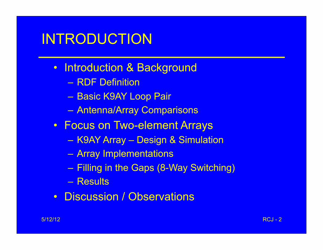
INTRODUCTION
• Introduction & Background– RDF Definition– Basic K9AY Loop Pair– Antenna/Array Comparisons
• Focus on Two-element Arrays– K9AY Array – Design & Simulation– Array Implementations– Filling in the Gaps (8-Way Switching)– Results
• Discussion / Observations
5/12/12 RCJ - 3
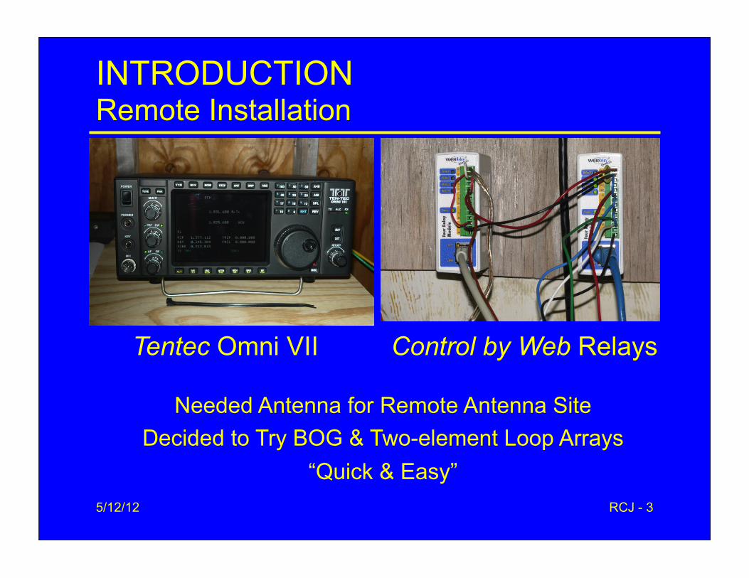
INTRODUCTIONRemote Installation
Tentec Omni VII Control by Web Relays
Needed Antenna for Remote Antenna SiteDecided to Try BOG & Two-element Loop Arrays
“Quick & Easy”
5/12/12 RCJ - 4
INTRODUCTION
• Poor Ground Conditions – Very rocky with rock shelves and red clay – Ground conductivity: 2-3 mS/m
• Loops Seem Most Effective Receiving Antennas in My Locations
• Needed Antenna for Remote Antenna Site– Decided to try BOG & two-element loop arrays
(Quick & Easy)• This Presentation Concentrates on the
Performance of Two-Element K9AY Arrays
5/12/12 RCJ - 5
• Second Element Offers Significant RDF Increase• As in a Yagi, the second element adds the most• Straight-Forward Implementation
– Hi impedance amplifiers/No matching transformers– Robust to both phase & amplitude errors– Loop direction switching required
• Potential Problems– Beam width narrows (98o)– RDF reduced by 2.5 dB at ±45o points
• Explore 8 Direction Switching
INTRODUCTIONTwo-Element Arrays

5/12/12 RCJ - 6
BACKGROUNDRDF: Receiving Directivity Factor
• Design Goal Here: Maximize RDF
• RDFdB = Gfor(dB) - Gavg(dB)
– Noise generally comes in from all directions
– RDF compares the main antenna lobe gain to the average gain over the whole hemisphere of the antenna
– Attributed to W8JI
5/12/12RCJ-8
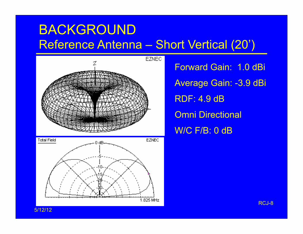
BACKGROUNDReference Antenna – Short Vertical (20’)
Forward Gain: 1.0 dBi
Average Gain: -3.9 dBi
RDF: 4.9 dB
Omni Directional
W/C F/B: 0 dB
5/12/12 RCJ - 8
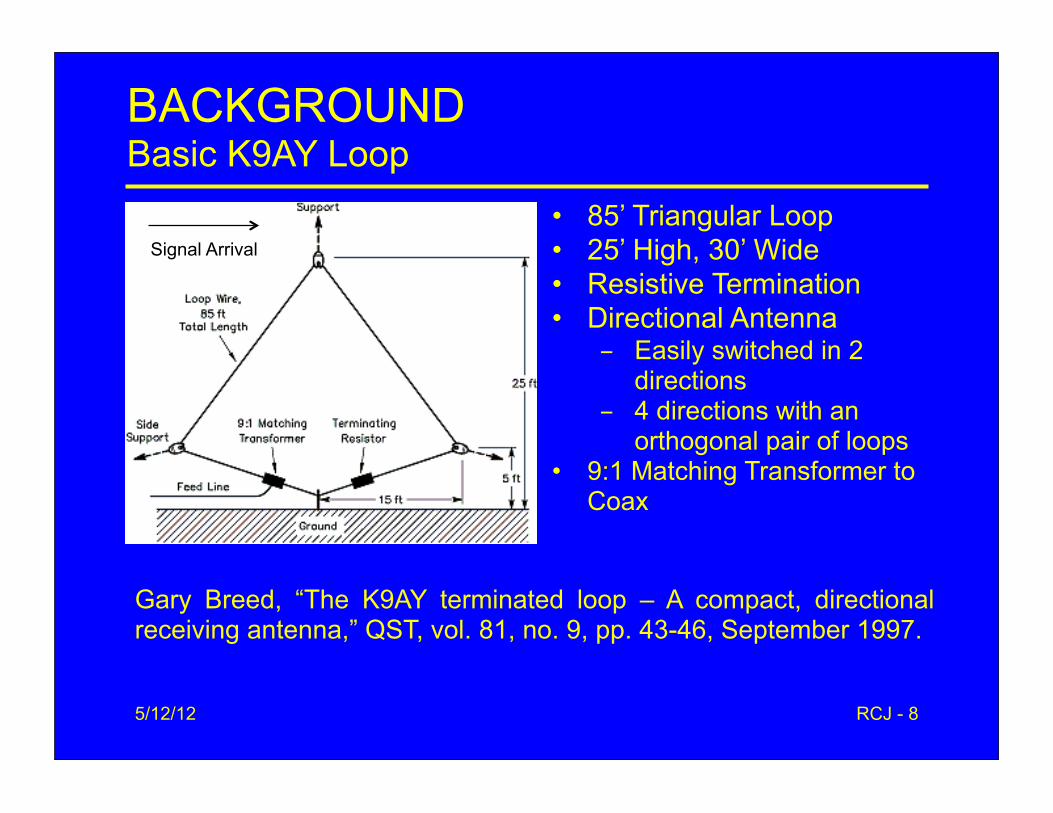
BACKGROUNDBasic K9AY Loop
• 85’ Triangular Loop• 25’ High, 30’ Wide • Resistive Termination• Directional Antenna
- Easily switched in 2 directions
- 4 directions with an orthogonal pair of loops
• 9:1 Matching Transformer to Coax
Gary Breed, “The K9AY terminated loop – A compact, directional receiving antenna,” QST, vol. 81, no. 9, pp. 43-46, September 1997.
Signal Arrival
5/12/12 RCJ - 9
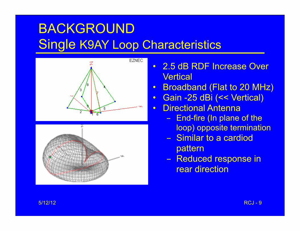
BACKGROUNDSingle K9AY Loop Characteristics
• 2.5 dB RDF Increase Over Vertical
• Broadband (Flat to 20 MHz)• Gain -25 dBi (<< Vertical)• Directional Antenna
- End-fire (In plane of the loop) opposite termination
- Similar to a cardiod pattern
- Reduced response in rear direction
5/12/12 RCJ - 10
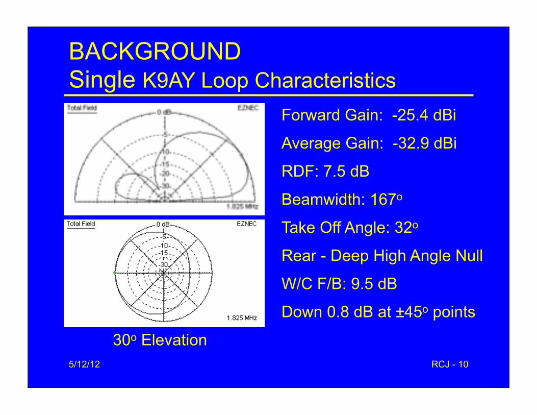
BACKGROUNDSingle K9AY Loop Characteristics
Forward Gain: -25.4 dBi
Average Gain: -32.9 dBi
RDF: 7.5 dB
Beamwidth: 167o
Take Off Angle: 32o
Rear - Deep High Angle Null
W/C F/B: 9.5 dB
Down 0.8 dB at ±45o points
30o Elevation
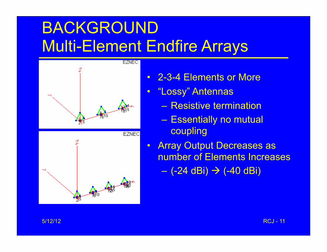
BACKGROUNDMulti-Element Endfire Arrays
• 2-3-4 Elements or More• “Lossy” Antennas
– Resistive termination– Essentially no mutual
coupling• Array Output Decreases as
number of Elements Increases – (-24 dBi) (-40 dBi)
5/12/12 RCJ - 11
5/12/12 RCJ - 12
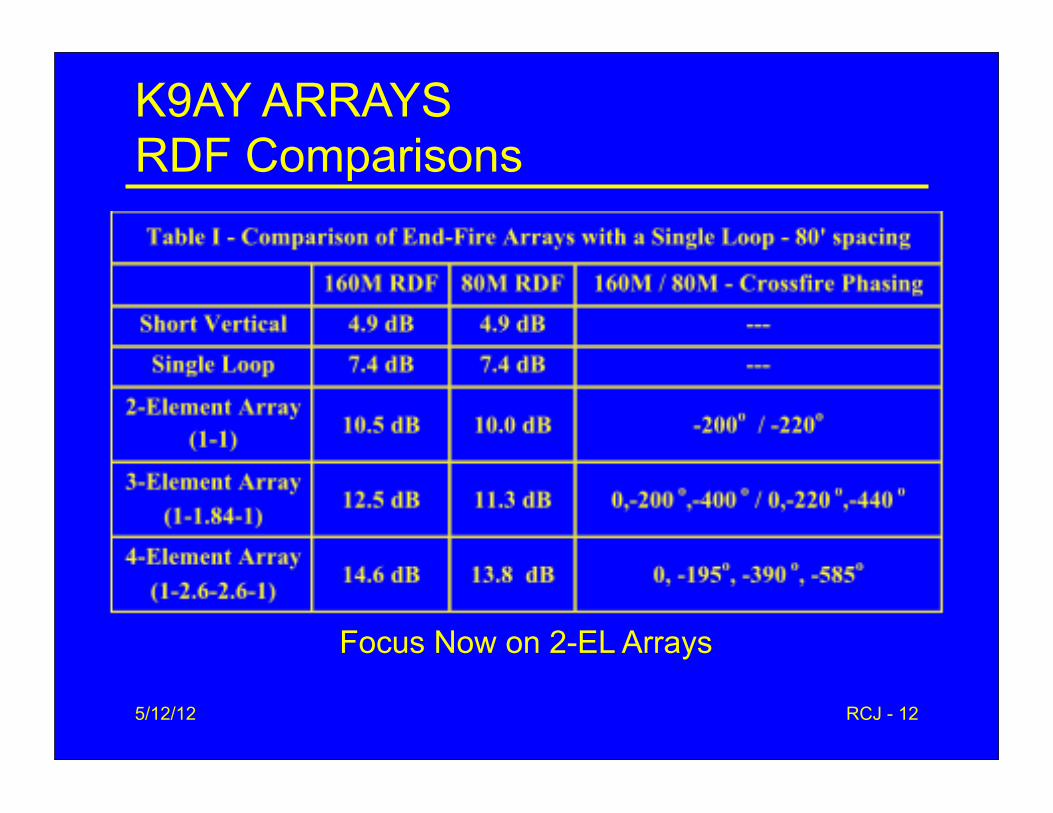
K9AY ARRAYSRDF Comparisons
Focus Now on 2-EL Arrays

5/12/12 RCJ - 13
Two-Element End-Fire ArrayArray Optimization - 160 M / 1.825 MHz
Element 2 Phasing (-200o)
• Two-Element Array- Equal amplitudes- Single phasing line- Rear element lags front
element
• Gain: -25.7 dBi
• RDF: 10.5 dB (+3 dB)
• Beamwidth: 96o
• W/C F/B: 16.6 dB
• Take Off Angle: 25o

5/12/12 RCJ - 14
2-ELEMENT ARRAY OPTIMIZATIONPerformance vs. Spacing
-195o Phasing
5/12/12 RCJ - 15
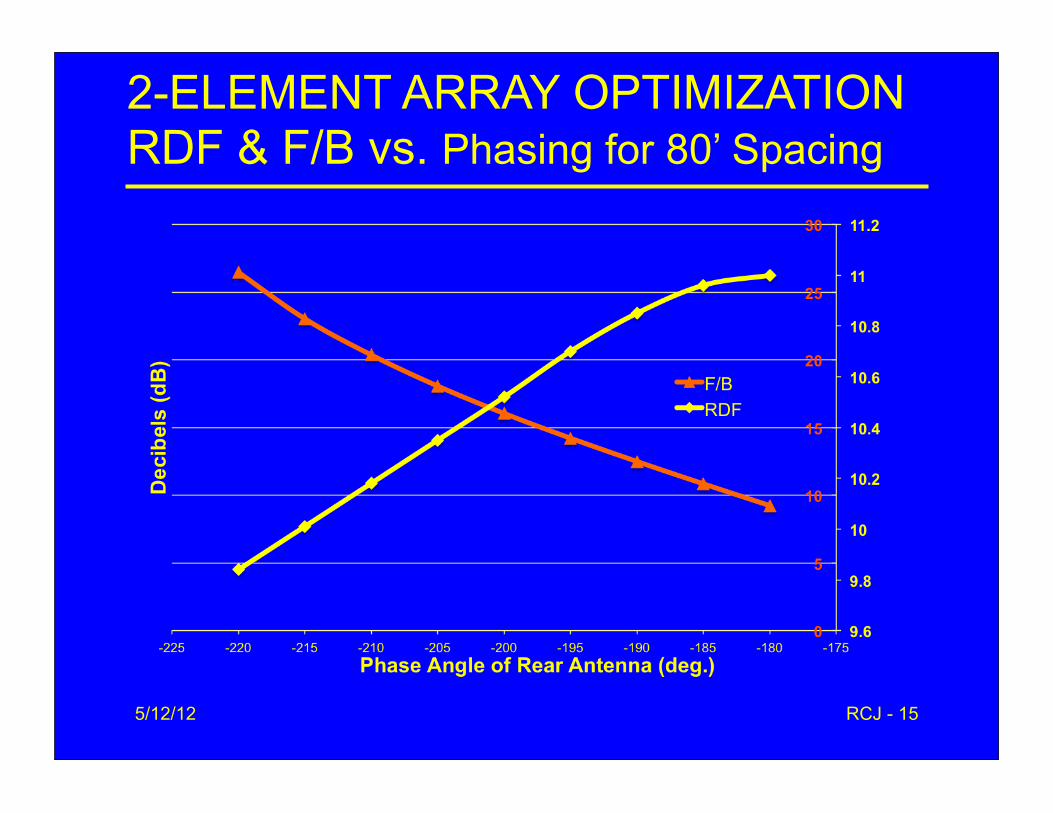
2-ELEMENT ARRAY OPTIMIZATIONRDF & F/B vs. Phasing for 80’ Spacing
5/12/12 RCJ - 16
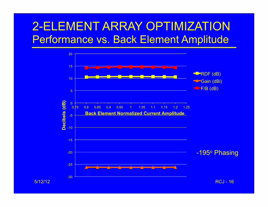
2-ELEMENT ARRAY OPTIMIZATIONPerformance vs. Back Element Amplitude
-195o Phasing
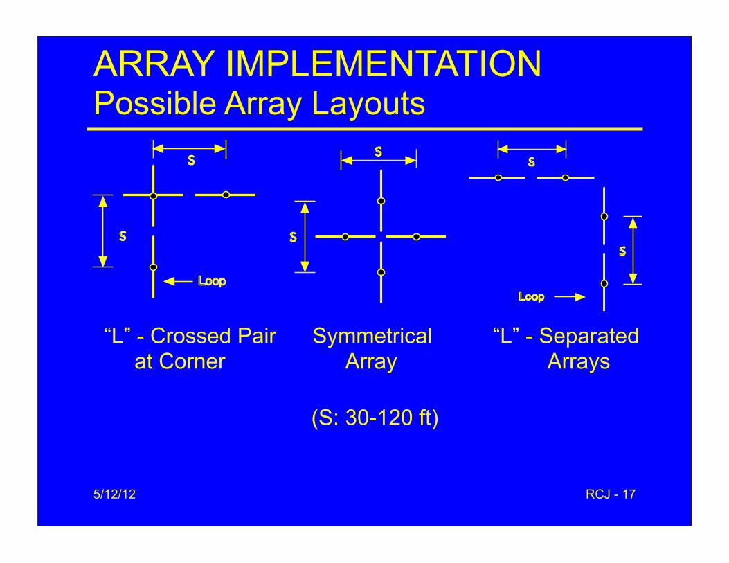
ARRAY IMPLEMENTATIONPossible Array Layouts
5/12/12 RCJ - 17
“L” - Crossed Pair Symmetrical “L” - Separated at Corner Array Arrays
(S: 30-120 ft)
5/12/12 RCJ - 18
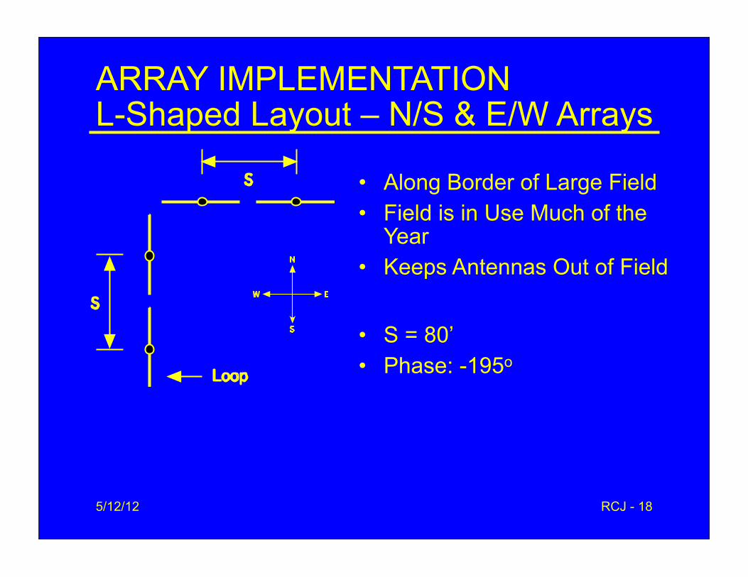
ARRAY IMPLEMENTATIONL-Shaped Layout – N/S & E/W Arrays
• Along Border of Large Field• Field is in Use Much of the
Year• Keeps Antennas Out of Field
• S = 80’• Phase: -195o
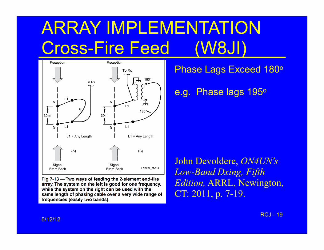
ARRAY IMPLEMENTATIONCross-Fire Feed (W8JI)
5/12/12RCJ - 19
John Devoldere, ON4UN's Low-Band Dxing, Fifth Edition, ARRL, Newington, CT: 2011, p. 7-19.
Phase Lags Exceed 180o
e.g. Phase lags 195o
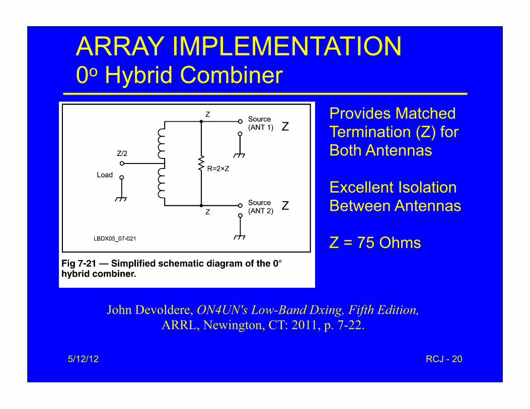
ARRAY IMPLEMENTATION0o Hybrid Combiner
5/12/12 RCJ - 20
John Devoldere, ON4UN's Low-Band Dxing, Fifth Edition, ARRL, Newington, CT: 2011, p. 7-22.
Provides Matched Termination (Z) for Both Antennas
Excellent Isolation Between Antennas
Z = 75 Ohms
Z
Z

ARRAY IMPLEMENTATIONTwo-Element Array Feed System
5/12/12 RCJ - 21
John Devoldere, ON4UN's Low-Band DXing, Fifth Edition, ARRL, Newington, CT: 2011, p. 7-22.
L = 100 ft in my case
W8JI Cross-fire Feed
2:1

5/12/12 RCJ - 22
ARRAY IMPLEMENTATIONCoax Phasing Lines
• Nominal Phase Shift for 160M: 195o-180o = 15o
• Phase Shift Expected on 80M: 28.8o
– 15.2o*(3.505/1.828) = 29.1o • Network or Antenna Analyzer
– Measure the resonant frequency or fault of open-circuited line
– Calculate phase by frequency scaling
5/12/12 RCJ - 23
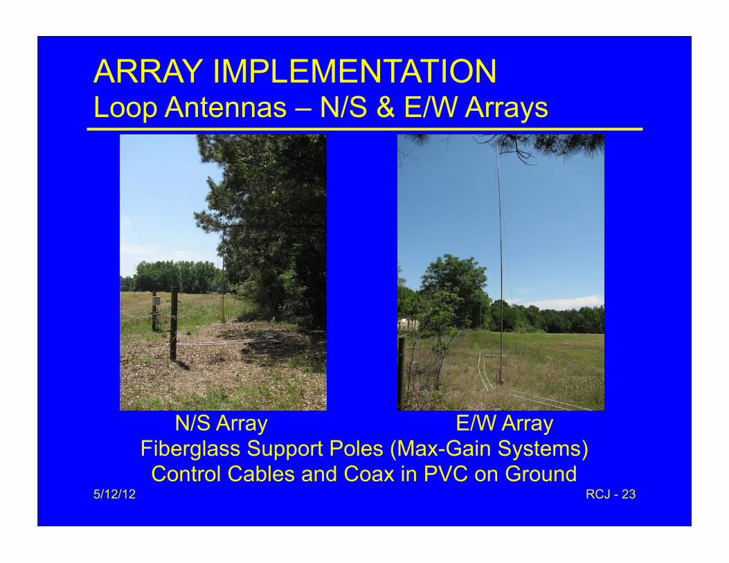
ARRAY IMPLEMENTATIONLoop Antennas – N/S & E/W Arrays
N/S Array E/W ArrayFiberglass Support Poles (Max-Gain Systems)Control Cables and Coax in PVC on Ground
5/12/12 RCJ - 24
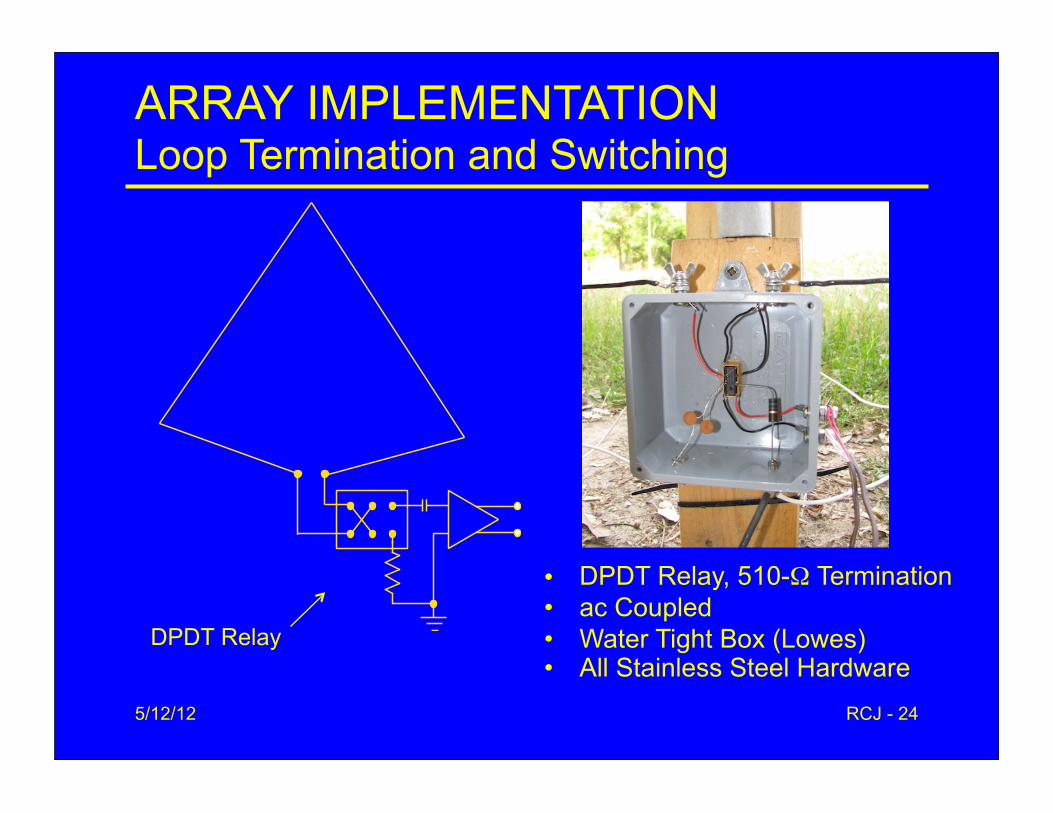
ARRAY IMPLEMENTATIONLoop Termination and Switching
DPDT Relay
• DPDT Relay, 510-Ω Termination• ac Coupled• Water Tight Box (Lowes)• All Stainless Steel Hardware
5/12/12 RCJ - 25
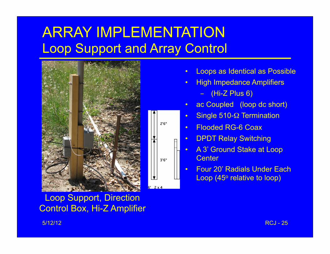
ARRAY IMPLEMENTATIONLoop Support and Array Control
Loop Support, Direction Control Box, Hi-Z Amplifier
• Loops as Identical as Possible• High Impedance Amplifiers
- (Hi-Z Plus 6)• ac Coupled (loop dc short)• Single 510-Ω Termination• Flooded RG-6 Coax• DPDT Relay Switching• A 3’ Ground Stake at Loop
Center• Four 20’ Radials Under Each
Loop (45o relative to loop)
5/12/12 RCJ - 26
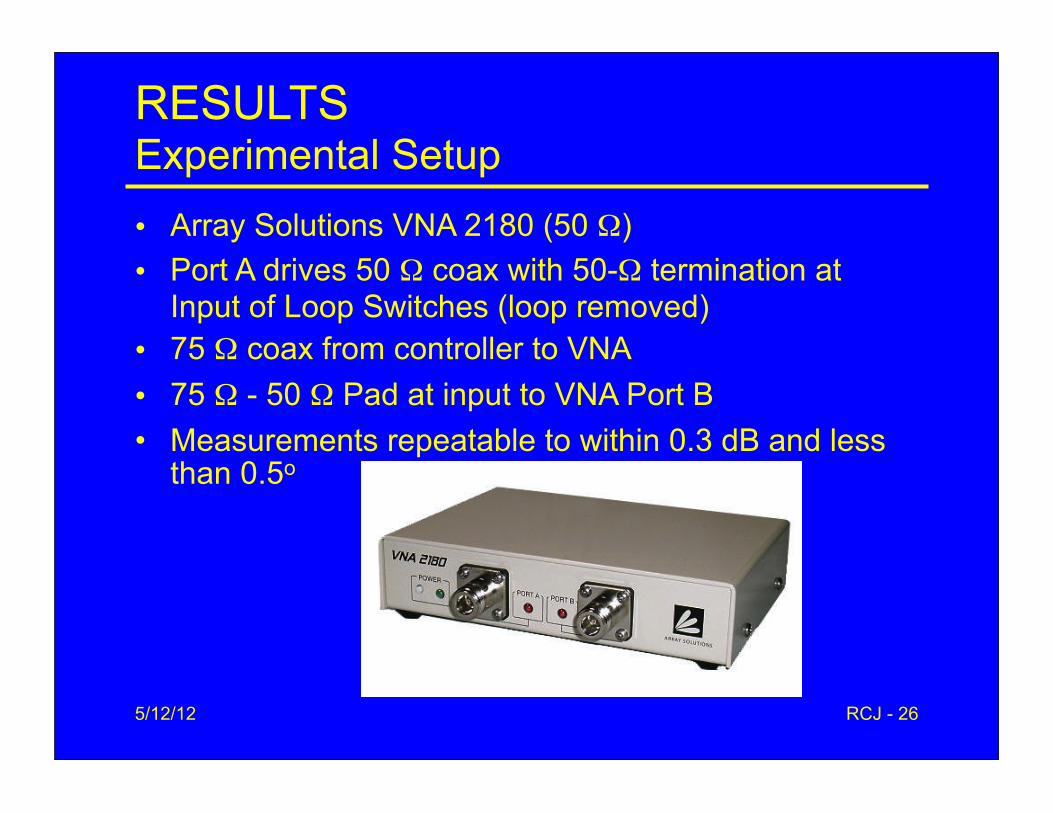
RESULTSExperimental Setup• Array Solutions VNA 2180 (50 Ω)• Port A drives 50 Ω coax with 50-Ω termination at
Input of Loop Switches (loop removed)• 75 Ω coax from controller to VNA• 75 Ω - 50 Ω Pad at input to VNA Port B• Measurements repeatable to within 0.3 dB and less
than 0.5o
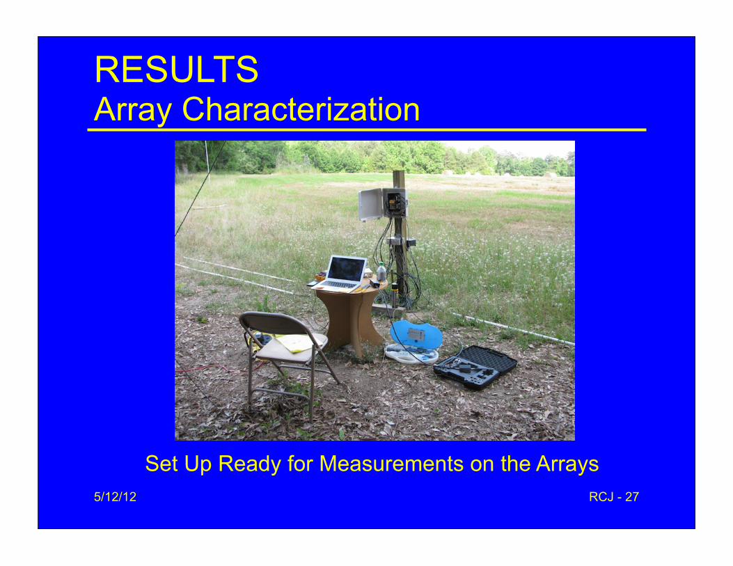
RESULTSArray Characterization
5/12/12 RCJ - 27
Set Up Ready for Measurements on the Arrays
5/12/12 RCJ - 28
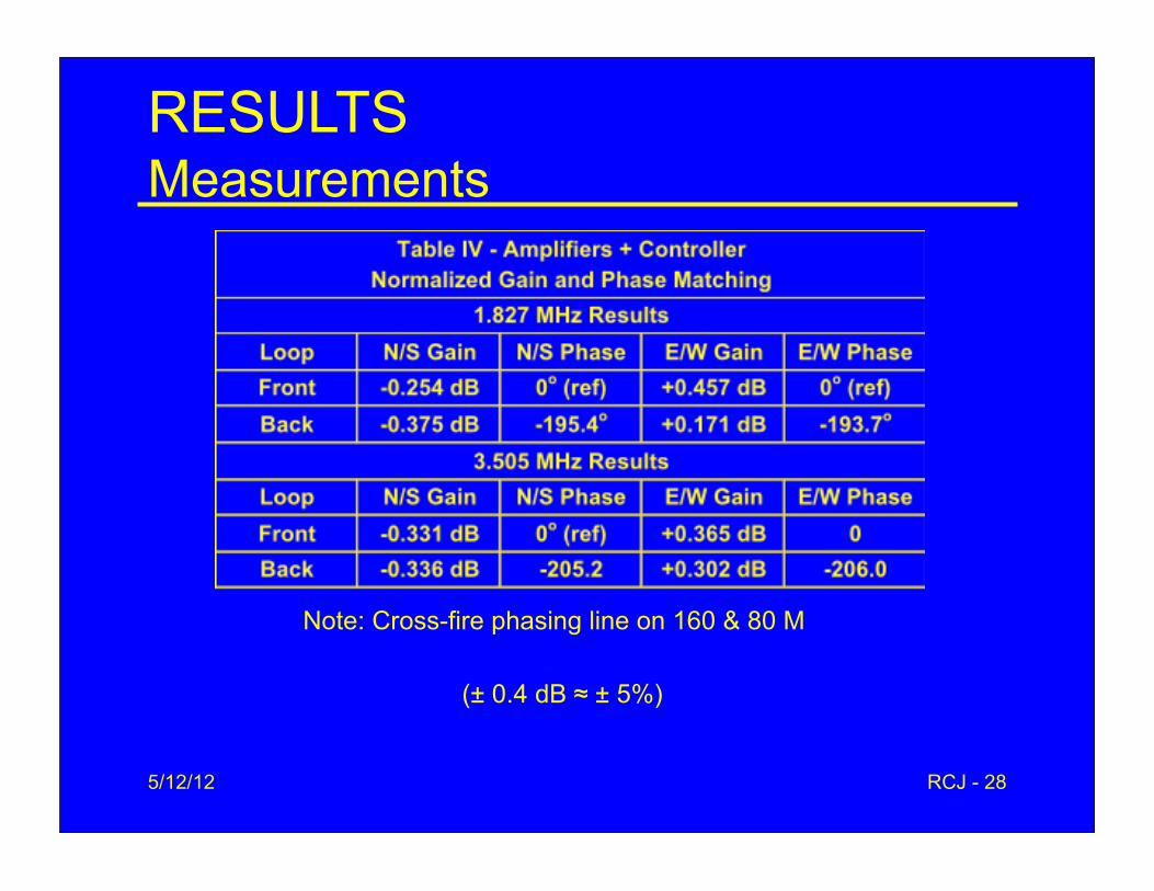
RESULTSMeasurements
Note: Cross-fire phasing line on 160 & 80 M
(± 0.4 dB ≈ ± 5%)

5/12/12 RCJ - 29
RESULTSFinal Simulations - 160 M
RDF 10.7 dBGain -26.4 dBiF/B 15.2 dB
RDF 10.7 dBGain -26.2 dBiF/B 15.8 dB
5/12/12 RCJ - 30
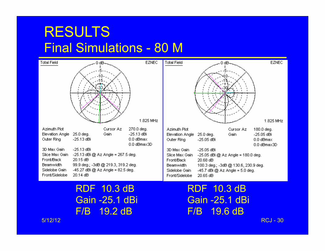
RESULTSFinal Simulations - 80 M
RDF 10.3 dBGain -25.1 dBiF/B 19.2 dB
RDF 10.3 dBGain -25.1 dBiF/B 19.6 dB
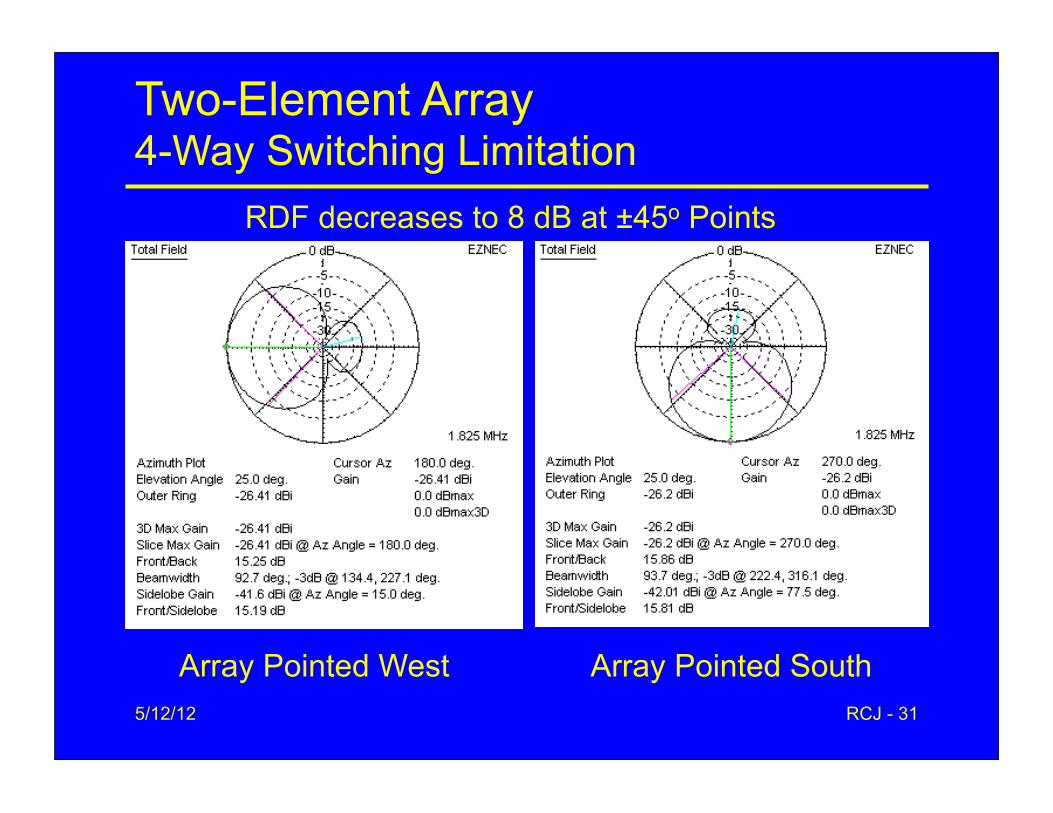
Two-Element Array4-Way Switching Limitation
5/12/12 RCJ - 31
Array Pointed West Array Pointed South
RDF decreases to 8 dB at ±45o Points

Two-Element Array4-Way Switching Limitation
• Multi-Element Arrays Have Narrow Beam Widths• Two-Element RDF
– 10.7 dB in primary directions– RDF decreases to 8 dB at ±45o points– Only slightly better than single loop
• Fill in the Gaps– Add two more arrays for ±45o directions– Combine patterns of two N/S & E/W arrays
5/12/12 RCJ - 32
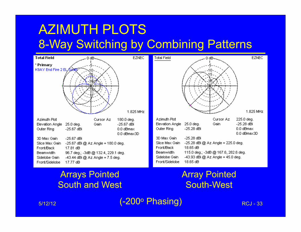
AZIMUTH PLOTS8-Way Switching by Combining Patterns
5/12/12 RCJ - 33
Arrays PointedSouth and West
Array PointedSouth-West
(-200o Phasing)
Two-Element Array8-Way Switching (-195o phasing)
• RDF– 10.7 dB in 4 Primary Directions– 9.7 dB at 45o Points– Gain Actually Somewhat Larger
(+0.3 dB) in 45o Directions
5/12/12 RCJ - 34
5/12/12 RCJ - 35
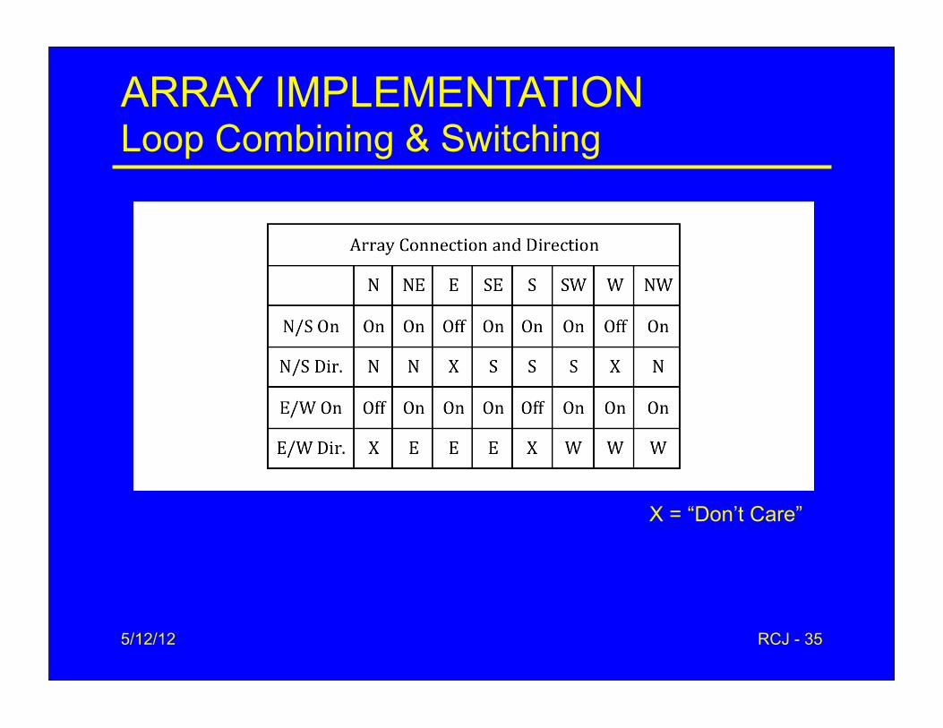
ARRAY IMPLEMENTATIONLoop Combining & Switching
X = “Don’t Care”
5/12/12 RCJ - 36
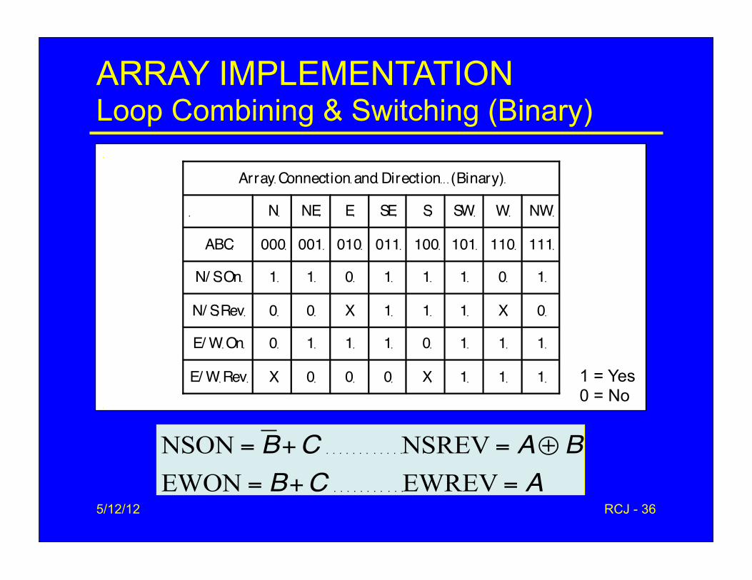
ARRAY IMPLEMENTATIONLoop Combining & Switching (Binary)
1 = Yes0 = No
5/12/12 RCJ - 37
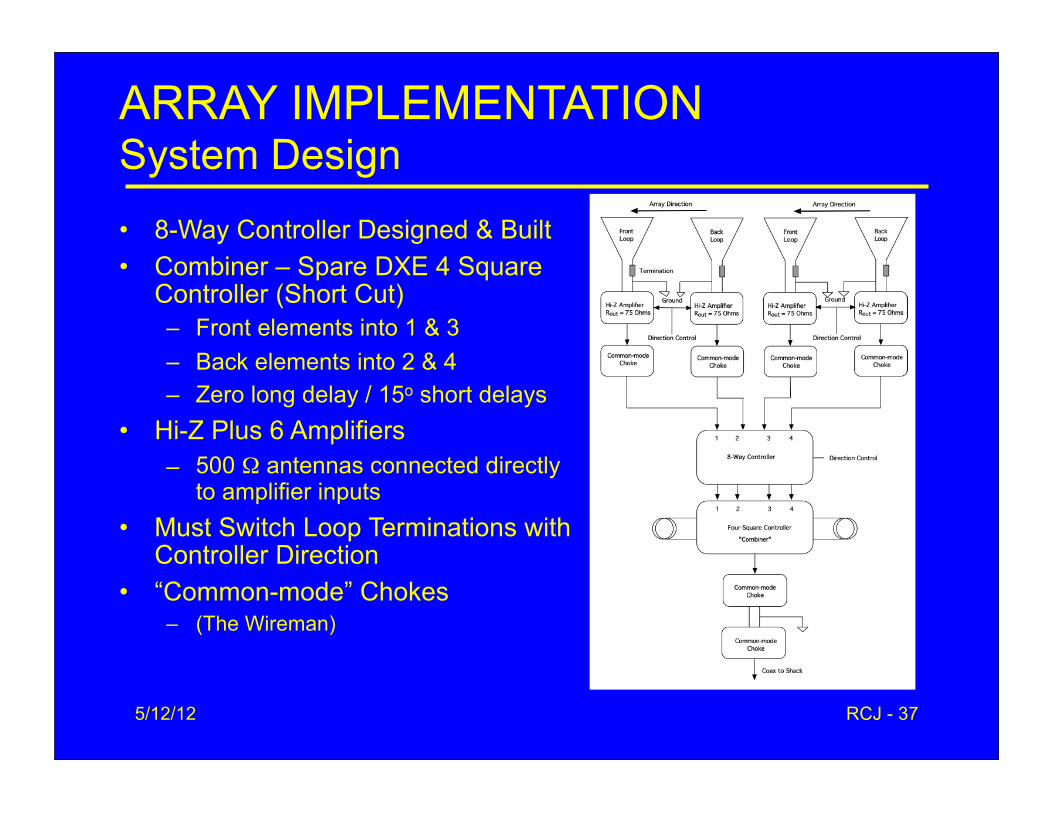
ARRAY IMPLEMENTATIONSystem Design• 8-Way Controller Designed & Built• Combiner – Spare DXE 4 Square
Controller (Short Cut)– Front elements into 1 & 3– Back elements into 2 & 4– Zero long delay / 15o short delays
• Hi-Z Plus 6 Amplifiers– 500 Ω antennas connected directly
to amplifier inputs• Must Switch Loop Terminations with
Controller Direction• “Common-mode” Chokes
– (The Wireman)
5/12/12 RCJ - 38
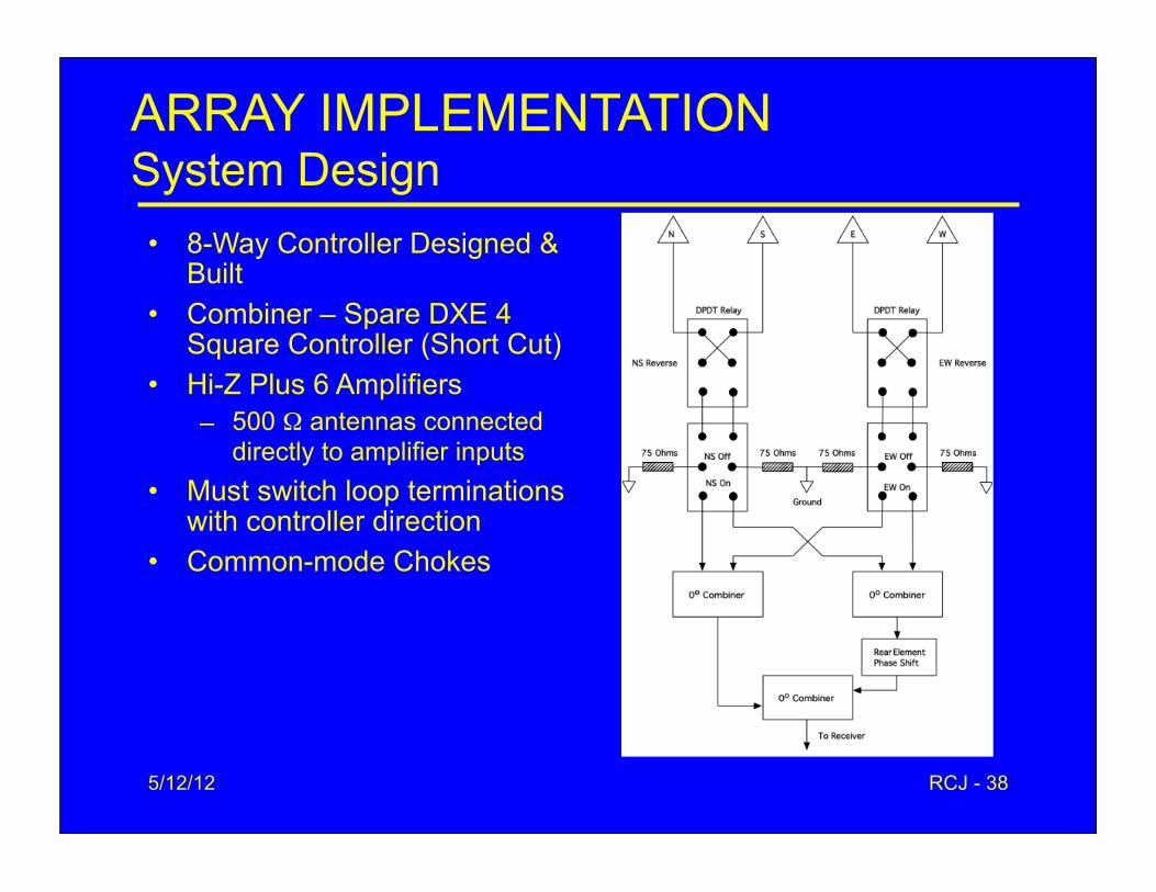
ARRAY IMPLEMENTATIONSystem Design
• 8-Way Controller Designed & Built
• Combiner – Spare DXE 4 Square Controller (Short Cut)
• Hi-Z Plus 6 Amplifiers– 500 Ω antennas connected
directly to amplifier inputs• Must switch loop terminations
with controller direction• Common-mode Chokes
5/12/12 RCJ - 39
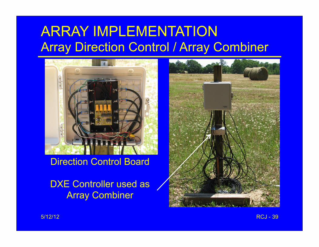
ARRAY IMPLEMENTATIONArray Direction Control / Array Combiner
Direction Control Board
DXE Controller used as Array Combiner

5/12/12 RCJ - 40
RESULTSFinal Simulations - 160 M
RDF 9.7 dB Gain -26.1 dBi F/B 14.4 dB
5/12/12 RCJ - 41
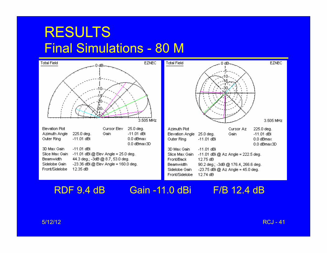
RESULTSFinal Simulations - 80 M
RDF 9.4 dB Gain -11.0 dBi F/B 12.4 dB
5/12/12RCJ - 42
RESULTSThe Bottom Line• Primary Array at Remote Receiver Site• Testing
– 1.6-1.8 MHz AM broadcast stations– 2.5 & 5 MHz WWV– 2.31 & 2.35 MHz Australian BC stations– 160M & 80M DX signals
• 8 Directions Readily Apparent• 7O6T (Gone the Best Night – Of Course!)
– 80 M• Solid copy NE on 5/6/12 and 5/8/12; SSb copy 5/11• Good copy on 5/7 (except for nearby storm qrn)• Marginal copy N & E
– 160 M• No TB Copy on Any Antenna (as 5/12/12)!
5/12/12 RCJ - 43
RESULTSThe Bottom Line (cont.)• Similar Technique Being Used At Home QTH with
Pair of Three-Element Arrays• Should have Used Gray Code• Will Probably Reduce Spacing• 50-ft Array with Crossfire Feed Maintains Pattern on
40 M (9 dB RDF)• 500’ BOG Comparison (Not Done)
– Chewed up by “critters”– A 60’ BOG doesn’t work nearly as well as the 500’ version
• Wellbrook K9AY Phased Array– www.wellbrook.uk.com/K9AYphasedarray.html
5/12/12 RCJ - 44
REFERENCES1. Gary Breed, “The K9AY terminated loop – A compact, directional receiving
antenna,” QST, vol. 81, no. 9, pp. 43-46, September 1997.
2. Gary Breed, K9AY, "Arrays of K9AY Loops: "Medium-sized" low band RX antenna solutions," Sept. 15, 2007. http://www.aytechnologies.com
3. John Devoldere, ON4UN's Low-Band DXing, Fourth & Fifth Editions, ARRL, Newington, CT: 2005 & 2011.
4. Dallas Lankford, http://groups.yahoo.com/group/thedallasfiles5. http://www.fcc.gov/mb/audio/m3/index.html6. Hi-Z Antennas 4-Square, http://www.hizantennas.com
7. DX Engineering 4-Square, http://www.dxengineering.com8. Max-Gain Systems, http://www.mgs4u.com
9. The Wireman, http://www.thewireman.com10. Richard C. Jaeger, K4IQJ “Multi-Element End-fire Arrays of K9AY Loops,”
expanded version of 2011 Dayton presentation, May 15, 2011, available at


