
Improving Energy-Efficiency of Location-Triggered Applications On Smartphones
74
IT 13 038 Examensarbete 30 hp Juni 2013 Improving Energy-Efficiency of Location-Triggered Applications On Smartphones Yemao Man Institutionen för informationsteknologi Department of Information Technology
Transcript of Improving Energy-Efficiency of Location-Triggered Applications On Smartphones

IT 13 038
Examensarbete 30 hpJuni 2013
Improving Energy-Efficiency of Location-Triggered Applications On Smartphones
Yemao Man
Institutionen för informationsteknologiDepartment of Information Technology


Teknisk- naturvetenskaplig fakultet UTH-enheten Besöksadress: Ångströmlaboratoriet Lägerhyddsvägen 1 Hus 4, Plan 0 Postadress: Box 536 751 21 Uppsala Telefon: 018 – 471 30 03 Telefax: 018 – 471 30 00 Hemsida: http://www.teknat.uu.se/student
Abstract
Improving Energy-Efficiency of Location-TriggeredApplications On Smartphones
Yemao Man
Numerous Location-Based Applications (LBAs) have been emerging in oursmartphones over the past several years. Most of them are user-triggered LBAs whichheavily depend on manual operations of end users, therefore easy to lose theiraccessibility and usability when fail to get instructions in time. While periodic dutycycling of location sensing can guarantee the accuracy of the location and reliability ofthe desired triggered events, this pattern brings severe battery draining problemcaused by power-intensive sensor, let alone redundant high-energy-consumptionsensing operation from multiple LBAs without coordination.
In contrast, location-triggered applications take the responsibility to manage thelocation sensing intelligently. They bring better user experiences by performingactions automatically when reaching predefined locations. This paper proposesadaptive approaches to design energy-efficient location-triggered applications andfurther models the middleware to build integrated application framework for multiplelocation-triggered applications in general for energy concern.
In the evaluation, business-independent location-triggered applications areimplemented in the unified application framework and tested under various scenarios.The results have verified improved usability, higher customization capability andenergy efficiency validity of the location-triggered applications and underlyingapplication framework. The establishment of the unified location-triggered applicationframework provides the reference model for general intelligent energy-efficient LBAdevelopment in the future, while broadening the actual use of location-based servicefor mobile cloud computing.
Tryckt av: Reprocentralen ITCIT 13038Examinator: Ivan ChristoffÄmnesgranskare: Christian RohnerHandledare: Edith Ngai


Acknowledgements First of all, I would like to give my deepest gratitude to my
supervisors Edith Ngai and Yan Liu for their patience, great
supportandconstructivesuggestions.TheirexpertiseinComputer
Scienceandpositivecharactersinlifealwaysmotivatemeexcelin
myprofessionforcontinuedexcellence.
Iwould also thankmy reviewer Christian Rohner and examiner
IvanChristoffwhoarewillingtogivemeadviceinboththeoryand
practice.Inaddition,itwouldnothavebeenpossibletofinishthis
work without the support from respectful teachers Anders
Berglund,PingWuandLiamMcNamaraaswellaslovelyresearch
fellowsKamyarNiroumand,BeLanglos,FredrikBjurefors,Simon
Bertilsson,SoodeGholamzadehandTommyMattson.Iappreciate
the encouragement fromallmy classmates in Sino‐Swedish Joint
MasterProgrammeinComputerScienceandSoftwareEngineering
inbothUppsalaUniversityandTongjiUniversity.
Special thanks for my girlfriend Yanzhu Mu who is always
supportingme behindmy back andmy friend Zhanghuan Gong
whodoesnotmindreplyingSMStoafriend8000kilometersaway
inthemiddleofthenight.
Imightforgeteverythingbutnotthis‐thanksformyparents,who
gaveme lifeandhavemademe theman Iam today.Everything
achievementImadeisduetotheirsupportandlove.


Contents
Chapter 1. Introduction ........................................................................................ 1
1.1 Background................................................................................................................ 1
1.2 Problem Isolation and Motivation ........................................................................... 3
1.3 Thesis Structure ........................................................................................................ 6
Chapter 2. Related Research and Techniques Study ......................................... 8
2.1 Location Acquisition ................................................................................................. 8
2.2 Related Work............................................................................................................. 8
2.3 Techniques Study on Android ................................................................................ 10
2.3.1 Android Service in Auto-Triggered Pattern ....................................................... 10
2.3.2 Location Update and Energy Consumption in Android Phones ...................... 11
2.3.3 IPC Infrastructure ............................................................................................... 13
2.4 Summary .................................................................................................................. 15
Chapter 3. Location-Triggered Service Pattern ............................................... 16
3.1 Location-Triggered Service Pattern ...................................................................... 16
3.2 Geo-fenced Areas ..................................................................................................... 17
3.3 Triggering Process Analysis .................................................................................... 18
3.4 Triggered Actions Categorization .......................................................................... 20
3.5 Logistic Mapping ..................................................................................................... 21
3.6 Summary .................................................................................................................. 22
Chapter 4. Location-Triggered Application and Sensor Schedule Strategy
Design ................................................................................................................... 23
4.1 Location-Triggered Actions Design Instance........................................................ 23
4.2 Policy Tuple Design ................................................................................................. 23
4.3 Location-Triggered Process Modeling .................................................................. 26
4.4 Energy-Efficient Localization Strategy Analysis and Design .............................. 27
4.4.1 GPS Update Interval Estimation Analysis ......................................................... 28
4.4.2 Orientation, Bearing and ................................................................................. 30
4.4.3 Location Estimation Process ............................................................................... 32

4.4.4 Estimation Control Mechanism in Multiple Triggered Areas .......................... 34
4.4.5 Update GPS Interval Time on Android .............................................................. 36
4.4.6 Internal Sensor Scheduling Strategy .................................................................. 36
4.5 Summary .................................................................................................................. 38
Chapter 5. Location-Triggered Applications Middleware and Integrated
Framework Design .............................................................................................. 39
5.1 Middleware Analysis and Design ........................................................................... 39
5.1.1 Interval Decision Maker Algorithm .................................................................... 39
5.1.2 Intrinsic Data Generator In The Framework .................................................... 43
5.2 Framework Implementation Hierarchy and Design on Android ....................... 44
5.3 Summary .................................................................................................................. 48
Chapter 6. Location-Triggered Application and Framework Evaluation ..... 49
6.1 Experiment Objects ................................................................................................ 49
6.1.1 Location-Triggered Application Instances ......................................................... 49
6.1.2 Location-Triggered Application Manager ......................................................... 52
6.1.3 Periodic Location-Detection Application ........................................................... 52
6.2 Location-Triggered Areas Description .................................................................. 53
6.3 Deployment Methods .............................................................................................. 54
6.3.1 Testing Group ....................................................................................................... 55
6.3.2 Deployment Approaches ...................................................................................... 55
6.4 Evaluation Results ................................................................................................... 56
6.4.1 Scenario 1: Single Application ............................................................................ 56
6.4.2 Scenario 2: Multiple Applications ....................................................................... 60
6.5 Summary .................................................................................................................. 62
Chapter 7. Conclusion ........................................................................................ 63
7.1 Summary .................................................................................................................. 63
7.2 Future Work ............................................................................................................ 63
References ............................................................................................................ 65

1
Chapter 1. Introduction
1.1 Background
With the development of mobile internet, people have unveiled the curtain of intelligent
mobile device, cloud computing, applications on smart phones, due to the convenience of
the handheld equipment and powerful functions of the sensors on device. Specifically, the
new era of the localization application has arrived with the prosperity of Location-Based
Applications (LBAs) that are emerging everyday in our daily life. In conventional LBAs,
it would first use techniques like GSM, Wifi or GPS to position the user, normally the
coordinates of the user, and then fetch the mesh-up service that is related to the user’s
current location from the remote servers through the network as Fig. 1.1 shows below.
Figure 1.1 Localization and Service Fetch in LBAs
No matter on the actual application platform of Google Android or iOS, the majority
of Location-based Service (LBS) can be generally categorized into the following three
parts based on their business intention and functionalities:
(1) Venues Check-in Apps
Foursqure[1] would be the typical application for venues check-in service in the
user-triggered pattern, shown in the Fig. 1.2. In such kind of service, users launch the
applications, get the current coordinates with the GPS and WiFi techniques, check in
where they are right now and gain points with possible check-in badges. It is popular in
the markets not only because it takes advantage of the willing of locations possess from
the perspective of human psychology when users are granted as the “mayor” of some

2
certain places, but also because it unlocks the opportunities to gain value added service
from the view of business development.
Figure 1.2 Foursquare as the representative check-in LBA
(2) Social Connection
Compared to the traditional online social connection service, mobile social
connection is even more practical because it is generally based on the physical locations.
Users launch such applications to gain their current positions and their friends’ positions
to switch from online social service (e.g. find people) to offline connection (e.g. meet
people). This service could be easily implemented as the value added service of the
check-in applications. Google Latitude [2] is one of the many LBAs intended for social
connections, shown in the Fig 1.3. It is built in the user-triggered pattern.
Figure 1.3 Google Latitude as the representative social connection LBA

3
(3) Location Information Exploration
This type of LBS is intended to provide nearby information with customized search
conditions and preferences by fetching the data that is highly related to current location
from remote servers. People are very convenient to understand what type of service
nearby they can get immediately and the previous comments from other customers with
their active case-specific requests. As the dominant information LBA which has over 40
million users in China, Dianping [3] provides deep information about hotels, restaurants,
shopping malls, activities etc. based on the position requests from users, shown in the Fig.
1.4 below.
Figure 1.4 Dianping as the representative LBA for local information exploration
1.2 Problem Isolation and Motivation
As we see the LBAs are focusing on “Localization-Mobile-Social” triangle nowadays,
their business flows are all inevitably relying on the current location. In order to avoid the
battery draining issue by requesting GPS updates abusively, it is a natural outcome for
LBAs to adopt the current user-triggered pattern which heavily depends on end users'
manual operations, i.e., LBS demands the users’ efforts to turn on needed service at the
right time and obtain the accurate current positions from GPS.
User-triggered pattern in LBS is actually a compromise between energy consumption
and users positioning, because the user know exactly when to turn on GPS to get service
based on their location without excessively requesting power-intensive GPS. However
every coin has two sides: Such pattern indicates the possibility to easily lose the
accessibility and usability when fail to get instructions from users in time, especially
when it comes to the scenarios of natural disasters or secret intelligence collection on site.

4
The users are usually constrained to turn on GPS service in such scenarios which would
certainly sabotage the user experience.
Confronted with such limitation from user-triggered LBS, auto-triggered services are
needed because of their intrinsic characteristics for demanding less human interaction and
higher intelligence. This gives birth to the novel location-triggered applications in the
markets. In contrast, location-triggered applications bring better user experiences by
performing actions automatically when reaching predefined locations. As the novel
application pattern, location-triggered service is breaking the walls of unnecessary
conceptual load on users with improved logic in business flow, shown in the Fig. 1.5.
User Position BusinessRequest Trigger
Notify
UserTrigger
Notify
User-triggered
Location-triggered Business
Improve
Position
Figure 1.5 User-triggered versus location-triggered pattern
Such evolvement in the LBS on both iOS and Android platform is becoming reality,
as some event-triggered apps - basically are reminder apps such as Remind Me app in Fig
1.6, are taking predefined locations or time as the trigger for upcoming desired events.
Figure 1.6 Built-in location and time triggered app “Remind Me” in iOS

5
However there are still burdens of location-triggered pattern to be widely adopted as
the conventional user-triggered LBAs. First we need information about a user’s current
position in the application in an intelligent way. While periodic duty cycling of location
sensing by requesting GPS updates can guarantee the accuracy of the device location and
reliability of the desired triggered events, it also inevitably brings severe battery draining
problem caused by power-intensive GPS sensor. Specifically, it can reduce the phone's
battery life to less than nine hours [4]. We now understand why it turns out to be the user’s
responsibility to trigger the service in a conventional way.
The previous researches have proposed numerous solutions to improve the battery
life by either using lower accuracy localization methods such as WIFI or utilizing less
power-intensive sensors instead of GPS with optimized sensor scheduling strategy, they
might ignore the following factors:
(1) The constraints and characteristics in the actual location-triggered scenarios.
Compared to user-triggered LBAs, location-triggered applications take the
responsibility to manage the location sensing internally and intelligently. It ought to take
the advantage of predefined targets of interest to achieve energy efficiency.
(2) Multiple location-triggered applications with different business requirements
need to coordinate their sensing behaviors in a unified framework.
Among the location-triggered application in the markets now, some have taken
different strategy to deal with energy issues. Neer’s location reminder [5] chooses to do
location provider substitution by using Wifi or Cell-tower while learning user’s mobility
pattern. The in-development app Donde [6] and iOS Passbook [7] take advantage of
accelerometer combined with certain periodic location sensing updates. However, if you
install all of them on your smart phone and try to run them simultaneously, their hard
work for saving energy would be very likely in vain, because the applications are
developed by different companies with different business goals. Basically they don’t care
about the sensing behaviors from other applications since they might adopt totally
different hierarchy to achieve their business targets.
Without a doubt, it will arouse the problem of redundant GPS request, when one
application requests location update with GPS in its own business flow and only 10
seconds later, another application requests location update with GPS again. Obviously the
user is still at the same place but the expensive price for the second GPS calling has been
paid.
In summary, the current situation in the LBS markets, the future LBS evolvement
tendency, and the lack of general design principles as well as unified framework for
energy efficient location-triggered pattern drive us with the following motivations:
6
1) Though there are many LBAs in the existing platforms, only a very few of them
are based on locations to trigger actions. Considering the potential scenarios for
more service to be triggered in associate with locations, and the tendency that
more apps are turning from user-triggered to auto-triggered, we believe it needs
to obey certain general design principle to sparkle events automatically.
Specifically, the mechanism to profile the actions that it chooses to perform with
respect to the predefined locations needs to be well studied and designed.
2) Previous work on energy efficiency for normal LBAs are not based on
predefined places of interest as the target destinations in mobile phones. This
inspires us to delve deeper in terms of energy consumption challenges we will be
facing in mobile location-trigger applications, taking advantage of the
geometrical composition of these destinations in the map, to duty-cycle GPS
with more intelligent sensor scheduling strategy bearing in mind.
3) There is barely research about improving battery performance when it comes to
multiple location-based applications on smart phones in the future, especially for
the novel location-triggered applications. There is no need to waste energy on
the expensive but redundant operations from different applications. In order to
overcome the difficulties that multiple location triggered applications with
different business flows to achieve the same energy efficiency goal for the user,
we need middleware to adjust their operations in a unified location-triggered
application framework on smart phones.
1.3 Thesis Structure
According to the previous chapters study, conventional LBS client systems on the end
user’s handheld device are primarily launched based on the user’s commands. The
customized service is always started from requesting the current position through GPS
when WIFI and Network are not available, which is deemed as the most expensive
operation in energy consumption. This type of interaction pattern essentially relies on the
users to be the “accuracy controller”. The Location-triggered applications will, in contrast,
take the responsibility to localization and broaden the LBS usage scenarios, given the
appropriate design principles and general application framework.
The general design principles and development framework for energy efficient
location-triggered applications on smartphones have not systematically studied by far.
Confronted with their case-specific issues, this paper will delve deeper in the
characteristics of location-triggered applications on smartphones. The work is primarily to
research the key concepts and design factors from the perspective of general
location-triggered applications, and how the applications will coordinate each other in a
unified framework for energy efficiency, considering their different business flows. There
should be vast potential researching interests on how to structure and design a framework

7
for multiple location-triggered applications, for either data communication or internal
behaviors, while achieving energy efficiency and data fidelity.
The following chapters are structured as shown below:
Chapter 2: This chapter researches the localization techniques and the previous
work for improving energy efficiency of positioning. Since we are going to build
the general framework for multiple location-triggered applications on Android, it
also delves deeper in needed techniques and platform knowledge in Android
implementation.
Chapter 3: This chapter discusses the pattern and mechanism of the general
location-triggered service on mobile device, triggering process analysis, the
functionalities of on-device sensors and rules to bind behaviors to places. The
concepts proposed in this chapter will be served as the theoretical base for
design approaches in the rest chapters.
Chapter 4: This chapter focuses on the sensor schedule strategy for
location-triggered applications based on the position of the user. It discusses the
estimation algorithm and co-working flow for on-device sensors to conserve
energy. The design principles are based on the previous concepts of triggering
mechanism and android sensor-related development. This is one of the core
guidelines for designing the general location-triggered applications on
smartphones.
Chapter 5: This chapter designs the middleware used in the location-triggered
applications to make the mobile application environment as an integrated
energy-efficient framework. Based on the single location-triggered application
design principles, the framework is intended to provide the unified energy
efficient running environment for multiple applications to request service and
conduct corresponding behaviors as needed.
Chapter 6: This chapter will deploy the implementation on Android smartphones
and conduct the experiments in the real-world scenarios. It evaluates the design
approaches on the location-triggered applications and its energy consumption, as
well as the robustness and efficiency from the implemented integrated
application framework.
Chapter 7: This chapter summarizes the work in the thesis and proposes the
future work for further improvements and corresponding research interests.
8
Chapter 2. Related Research and Techniques
Study
2.1 Location Acquisition
Location acquisition is a prerequisite for location-triggered services. The position of
mobile users can be obtained through either network or the Global Positioning System
(GPS), which is a space-based satellite positioning system established in 1960s [25]. There
are 24 satellites around the earth and the sending signals continuously. Mobile devices
calculate the distance to at least four satellites from anywhere on the earth based on the
time stamps of these signals and positions of the satellites. The distances values can
generate an approximated position by trilateration. Different algorithm might be used to
compute.
Considering the external circumstance doesn’t always support the network
connection, and GPS is the most mature system that is supported widely in our
smartphones while costs the most energy, we assume our research context on novel
application framework design and energy concern is primarily for the GPS approach to
obtain positions.
2.2 Related Work
The past research has paid great attention to the position tracking approaches and sensing
strategies for energy concern. These researches can be roughly categorized into the
following parts.
Some researches are built on client and server pattern for mobile devices and location
server with the purpose to save bandwidth in transmission. Axel Küpper et al. [8] are
researching on minimizing messages amount between mobile clients and location server
during the proximity and separation detection process. Leonhardi et al. [9] are focusing on
the protocols improvement for updating location information in an energy-efficient way
between clients and server. These researches are founded on the higher level LBS, such as
distance calculation for moving objects, but lack the sensor usage strategy for positioning
need. Besides, our work is also not restricted with this communication pattern.
The periodic position updated triggered by device itself (A predefined interval t has
elapsed right before next request GPS update) or distance-based position update (Only
update GPS when the distance between devices is larger than a predefined threshold) are
the most frequently used approaches [10] but quite energy-expensive. The reason is GPS
takes a large percentage of the total power when the time to obtain the position

9
information. In order to solve these issues, some works are proposed to utilize low
power-consumption sensors (accelerometers in most cases) or techniques to track the
position or trajectory. For example:
EnTracked [11] is based on the point estimation and prediction of system
conditions and mobility with GPS and accelerometers to schedule position
updates moment. Their actual implementation is also restricted with the
Client/Server pattern. Another disadvantage is lacking coordination between
different sensors in the integrated schedule framework, especially for in distance
aware scenarios.
EnTrackedT [12] is focusing on joint trajectory tracking instead of merely discrete
location fixes by using accelerometer to check the mobility status. Even though
their model seems to be able to handle in different transportation modes, e.g.,
walking, running, biking or commuting by a car, the practical deployment is
merely focused on monitoring walking and driving.
Since low power consuming facility can replace the high one for the sake for energy,
the research is usually not alone with sensor substitution but also combining other
localization techniques. It usually combines lower accuracy WiFi with accelerometers [13],
Bluetooth [14] and cell-tower triangulation [15]. WiFi and GSM can last as long as 40 hours
and 60 hours [16] compared to the most expensive operations from GPS request. Such
solutions usually have clear constraints that the network should be available all the time.
What’s more, unlike our research focus, the previous studies focus more on tracking
approach rather than the geographic relation between the device and the targeted places.
There are also researches that concentrate on the user mobility detection and
contextual information collection to predict the future mobility. Usually the research
related with user’s mobility will concern much about the usage of on-device sensors and
even the techniques mentioned earlier. For example:
Brezmes et al. [17] are focusing on human movement’s detection with
accelerometer and pattern recognition. Similarly, I. Constandache et al. [4] and J.
Ryder et al. [18] are studying mobility pattern from human being for prediction
needs.
Tilak et al. [19] propose adaptive and predictive protocols to control positioning
based on mobility patterns.
Kim et al. [20] are combining on-device sensors and WiFi to understand a user’s
location context continuously, still in the circle of mobility study. Similarly,
Jurdak et al. [21] use empirical GPS and radio contact data to model the node
mobility to duty cycle strategies.

10
The user’s location-time history [14][22] plays important role in mobility pattern
study. Following this idea, Chon et al. [23] even propose a Markov decision
process-based adaptive duty cycling scheme to provide contextual information
about a user’s mobility.
However in the above works, the initiatives for efficient proximity and separation
detection between devices and user-defined places through elaborate designed sensor
scheduling strategy are missing so far or merely take marginally place.
The multiple LBAs issue was only mentioned by Zhenyun et al. [24] but their solution
only applies for the conventional LBAs synchronization. It is not suitable for
location-triggered applications in which case the intention ought to be set on the relation
between current location and interested predefined locations, with contrast to merely
tracking users in LBAs. Admittedly, the so-called piggybacking strategy for choosing the
best GPS registration seems to overcome the deficiency in Android which can only
coordinate the location update requests when GPS module is on and never off.
Nevertheless, the idle time for GPS is static and cannot be updated dynamically with
respect to the user speed and orientation, the important factors that are strongly related to
when to trigger desired events when the user is in the geo-fenced area. From a more
practical perspective of their deployment approach, the user must wipe the original
Android and install their ROM because of the modified source code below the application
framework, which will bring unbearable barriers to new Android users.
In conclusion, our work has the following unique contribution compared to previous
studies in these areas:
(1) Construct integrated energy efficient location-triggered application
framework by elaborate sensing strategy in geometrical relationship of
multiple locations.
(2) Build the middleware for multiple business-independent location-triggered
services coordination in an exportable way.
2.3 Techniques Study on Android
As this paper proposes the general application framework for location-triggered
applications used on Android platforms, it is necessary to study the characteristics of the
deployment platforms and techniques used for designing the integrated framework.
2.3.1 Android Service in Auto-Triggered Pattern
Android Service is an ideal solution for auto-triggered pattern in which actions are
performed automatically. Location-triggered applications need to wait for the appropriate

11
time to perform actions, so there is no need to provide interactive interfaces for users
during the long idle time. All of these algorithms and decision making strategies should
be performed in the background, without any interference from users. The intention is
also to eliminate the conceptual demand on users.
There are two ways to initiate Android service:
Start service
Bind service
Binding service is particularly suitable for Inter-Process Communication. Their
lifecycles are shown in the Fig. 2.1 below.
There are some notable differences in these two ways. If one service is initialized
through starting directly, then it will stop if any component kills the service by calling
stopService() method.
However, if we bind the service to initialize, then the service will be running the
whole time until all of components unbind the service by calling unbindService() method.
onCreate
onStart/onStartCommand
Service Start
onDestroy
Service Stop
Start Service
onCreate
onBind
Service Binded
onUnbind
onDestroy
Bind Service
Service Stop
Figure 2.1 Two ways to initialize the service in Android
2.3.2 Location Update and Energy Consumption in Android Phones
In order to use system location service on Android platform, we need to use
LocationManager class to retrieve these system services by merely running the method
Context.getSytemServie(Context.LOCATION_SERVICE). Given the criteria, we can

12
obtain the LocationProviders later:
NETWORK_PROVIDER
GPS_PROVIDER
The two providers can decide how the applications update their location information,
either through satellites or the cell tower and WiFi access points. GPS will consume much
more energy but return more precise location therefore we take this provider as our
energy efficiency research focus. After we have the providers and prepare the listeners for
the real time location updates from the GPS module on the phone, we can register for
updates to obtain the current accurate location information by calling this method:
requestLocationUpdates (locationProvider, minTime, minDistance,listener)
Figure 2.2 Location updates method used in Android development
The important trick lies in the second parameter minTime, because it stands for
minimum time interval between each individual location updates behavior. In principle,
this schema is designed for periodically running GPS updates with some certain interval
time value.
From this perspective, location-triggered applications need to track the user’s
location for triggering actions when it feels necessary. If the interval time is very small,
then the update behavior will become much more frequent, the user’s location
information will be more precise and reliable. However, if we need to set this number
small, then the frequent update behavior will definitely cause battery draining issue at the
same time. If we set a long time interval, then we will risk losing the track of the user ’s
location, in which case, saving energy will become meaningless. As it costs great energy
to update the location, setting an appropriate value for the update interval time is very
important to control the energy consumption, as it is essentially a tradeoff between energy
and location accuracy.
Nevertheless, we must jump out of the box of periodic fixed-frequency updates.
Suppose the user is way too much far from the target, then it doesn’t make any sense to
update periodically on the way to get closer. Since Android doesn’t allow dynamically
modifying the registration parameter for updates, how can we set “dynamic” value to
update interval time? The solution is to unregister the listener right after using it every
time and prepare a new one next time. By registration and un-registration, one LBS seems
to work fine with the dynamic interval. However multiple LBS will face the battery issues
for multiple asynchronous registration and un-registration operation. What makes the case
worse is that there’s no such a mechanism to guarantee that the location-triggered
applications runs in a synchronous context. The work [24] has identified the problem by

13
comparing the remaining battery level tendency between one LBA on mobile phone and
multiple LBAs on mobile phone, as Fig. 2.3 illustrates below.
Figure 2.3 Battery draining issue for multiple conventional LBAs
Location-triggered applications are confronted the same problem as long as we adopt
flexible interval mechanism. Considering the case-specific business flows and goals in
each individual independent location-triggered application, there’s no way to design every
location-triggered service to demand them watching for each other’s power-intensive
operation. The general integrated location-triggered framework must know to deal with
Inter-Process Communication (IPC) on the mobile phone.
2.3.3 IPC Infrastructure
We have noticed that it is very important to handle Inter-Process Communication
(IPC) to synchronize individual power-intensive requests from higher level in the
framework. Though there is a solution to coordinate the registration behaviors under the
application framework of Android in previous research [24], users must need to update the
Android firmware to make energy efficiency possible, merely for conventional LBS.
Their solution didn’t consider any autonomic characteristics of location-triggered
applications, which makes the usability lower in the actual deployment.
The core of Android is implemented in C. Native library and applications are written
in C++. The rest applications in upper level are developed in Java to guarantee these
applications can share the characteristics from the Android platform. To avoid the
practical issues when modifying the kernel OS code, this research will take the two
approaches above JNI layer to implement IPC in Android:
Binder framework
14
The core of Binder framework is Binder Kernel Driver (BKD), which are located in
the Android source code:
/drivers/staging/android/binder.c
/drivers/staging/android/binder.h
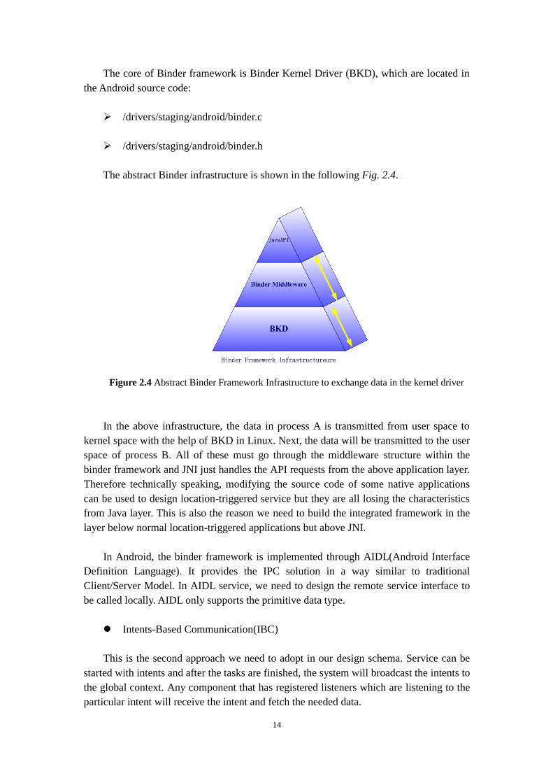
The abstract Binder infrastructure is shown in the following Fig. 2.4.
Figure 2.4 Abstract Binder Framework Infrastructure to exchange data in the kernel driver
In the above infrastructure, the data in process A is transmitted from user space to
kernel space with the help of BKD in Linux. Next, the data will be transmitted to the user
space of process B. All of these must go through the middleware structure within the
binder framework and JNI just handles the API requests from the above application layer.
Therefore technically speaking, modifying the source code of some native applications
can be used to design location-triggered service but they are all losing the characteristics
from Java layer. This is also the reason we need to build the integrated framework in the
layer below normal location-triggered applications but above JNI.
In Android, the binder framework is implemented through AIDL(Android Interface
Definition Language). It provides the IPC solution in a way similar to traditional
Client/Server Model. In AIDL service, we need to design the remote service interface to
be called locally. AIDL only supports the primitive data type.
Intents-Based Communication(IBC)
This is the second approach we need to adopt in our design schema. Service can be
started with intents and after the tasks are finished, the system will broadcast the intents to
the global context. Any component that has registered listeners which are listening to the
particular intent will receive the intent and fetch the needed data.

15
Since IBC needs to broadcast the intents to the global context, it is recommended to
deliver tiny messages. But it is still served as an effective approach to fulfill Inter-Process
Communication.
2.4 Summary
This chapter also discusses the related work about energy efficient localization techniques
and strategies. Later in the chapter, we delve deeper in the Android development concepts
for practical framework design and construction. These characteristics and formalized
principles in location-triggered service will be the cornerstones for the detailed strategy
discussion and middleware design. More specifically, the rest chapters will adopt IBC
combined with Binder Framework to design the location-triggered applications and
integrated application framework deployed on Android phones.

16
Chapter 3. Location-Triggered Service Pattern
This chapter discusses the pattern of general location-triggered applications on mobile
devices, logistic mapping schema for location-triggered service such as binding behaviors
to places, the functionalities of various sensors. All of the working mechanisms are served
as important reference in our actual design later in this work.
3.1 Location-Triggered Service Pattern
The auto-triggered category of mobile application is very likely to become a dominant
application field with the fast development of smartphones. This application category
refers to the application set which can intelligently monitor the physical parameters of the
cell-phones with the built-in sensors and/or hardware interfaces, and automatically trigger
either internal or external actions when these parameters meet some predefined conditions
as the environment changes from time to time.
Auto-triggered applications can monitor various parameters as the trigger to fire the
real actions, e.g. battery power, environmental noise, light intensity, etc. It normally uses
the built-sensor to fetch the current context because of its convenience. In some cases it
might need the external connected sensor mote to obtain the parameters. Note that time
could also be considered as one objective physical parameter to be the trigger.
Auto-triggered pattern enables flexible mesh-up service in a highly customized way. For
example, Remind Me App on iOS platform is a time-triggered app to remind people tasks
by vibrating and showing message on the screen. To improve the service and extend the
functionalities, the app could further upload data to remote server automatically and
return the data mining results. These types of auto-triggered service are providing more
accessible and usable interface to users intelligently. It represents a broadened stage for
the promising future of mobile cloud computing by customizing multiple services to be
triggered when the environment meets the needs.
Location-triggered applications stand for one specific implementation set in all of
these auto-triggered services on smartphones as Fig. 3.1 shows, which is, to trigger
corresponding actions on smartphones when detecting that the current location matches
any of those previous defined places of interest. The process needs no remind from users
but usually the other way around – end users might get notified that the location
conditions have been met and the further service is available. The notification actions are
the interfaces to the real business service, initializing the interaction process between
human and smartphones.

17
· Sound Playing
· SMS Notification
· Email Delivery
· Video Recording
· Voice Recording
· Vibration
· Breath Lamp
· Local data upload...
· Mobile Cloud Service
Request...
Trigger
LOCATION
TIME
On-deviceSensors
BATTERY
NOISE
LIGHT
...
Physical Parameters
Figure 3.1 Auto-triggered Services in Mobile Applications
There are reasons why this work gives more credits to location-triggered services in
the future LBS development. Compared to the most frequently used timer apps nowadays,
which are all timer-triggered service, location-triggered are not asking end users to
estimate the time when certain actions should be done. Time-triggered services put the
conceptual burden on users by asking them to estimate the time beforehand. If the users
want to be reminded to buy some milk after work, they need to estimate the time more or
less accurately. This is not the worst case because the users probably know when they
normally leave their offices. However, it will be a headache for users to be reminded
something like “ask Jack if he wants to buy something when I am buying milk at the
supermarket after work”, because it is hard to estimate when is the moment to arrive at
the supermarket. As we know, place is the fundamental element of our daily events and
tasks, so when people are moving and their tasks are highly related to the places,
location-triggered service will be the most usable and efficient one among all
auto-triggered service. Just imagine how efficient the information can be delivered if
people are reminded automatically about some special price when they pass by
supermarkets.
3.2 Geo-fenced Areas
Location-triggered service is based on the mobility of users and detection of the interested
locations. When a user is in the range of any predefined location, the system should
trigger the events to remind the user. So we need to model the predefined locations as the
reference context.
As we can understand, one predefined location can be composed of latitude and

18
longitude, i.e., the specific coordinates to describe where it is. However, this point could
hardly be on the user’s actual trajectory by coincidence. Considering the user can
approach to the target location from any direction and the possibilities of triggering events
should be same from these directions, the triggered location is modeled as the Geo-fenced
Areas (GA). It is a circle area which uses the coordinates as the center of the circle,
predefined triggered distance as the radius. We describe GA as
GA = <C,R> (3.1)
One example for Polacksbacken as the geo-fence area:
Lat: 59.84059Lon:17.64739R:80 meters
Figure 3.2 Geo-fenced areas for Polacksbacken as the triggered locations
As Fig. 3.2 shows above, it describes Polacksbacken as the targeted geo-fenced areas.
Except for latitude and longitude used in the 2D model of the predefined location
description, we can also use altitude for 3D space-triggered service in the future.
3.3 Triggering Process Analysis
When the user is moving from the start point to the destination point, location-triggered
application need to monitor the mobility status in an energy-efficient way while not
compromising accuracy too much. The intention is to understand the relation between a
user’s current location and the triggered geo-fenced areas. As Fig. 3.3 shows below, we
analyze the triggering process and decompose the procedures in the four stages.

19
R
No action
Actions off
Actions!v
No actionA
B
C
DL1
L2
Figure 3.3 Triggering Process Analysis
The geo-fenced area (C , R) as the dotted lines indicate, has the center point
C(LatitudeGA,LongitudeGA) and radius R. D represents the distance between the current
position P(Latitudet,Longitudet) and circle center C of the geo-fenced area. Dotted line L1
and L2 represent different trajectories of the user.
L1 is stating from a place far away from the geo-fenced area and approaching it
gradually, moving through the area and leaving in the end.
L2 is stating from a place far away from the geo-fenced area and approaching it
gradually, but not moving through the area.
The four stages from the above procedures is marked with A, B, C, D in the figure.
Therefore the triggering condition is discussed as below:
Stage A: When the user is far away from the geo-fenced area, i.e. , no
actions will be triggered.
Stage B: When the user is getting closer to the geo-fenced area, i.e. , no
actions will be triggered.
Stage C: When the user is entering the geo-fenced area, i.e. , actions will
be triggered.
Stage D: When the user is leaving the geo-fenced area, i.e. , triggering
actions will be off.
As for L2, there are no actions during the whole procedure.
The user’s location is changing as the time goes by. So the judgment for triggering
actions is made at every time point. Therefore for the purpose of tracking the mobile
device’s position, the coordinates are discrete distribution. More frequent we set the for

20
location update and judgment, more accurate trajectory we will get, paired with more
reliable location-triggered behaviors. However, as we discussed earlier, the energy cost
for frequent location update can’t be ignored because it will shorten the battery usage
time severely. The design should pay attention to the thoughts on the balance of necessary
location update behavior and triggering condition checking.
3.4 Triggered Actions Categorization
Inside the geo-fenced area, the actions might be triggered but in various forms. Thus we
need to categorize the triggered actions in respect to the relation between their behaviors
and the system environment, as Fig. 3.4 shows below.
Sensor/Hardware Interface
Internal System External System
Audi-tory
visualTempe-rature UV
Network
UploadDown-load
Service
Velo-city
Coordi-nates
acceleration
Orien-tation
Notification
Sound SMSVibra-tion
Sensor/Hardware Interface
Figure 3.4 Triggered actions categorization
The mobile device is an integrated system and the triggered actions could be part of
the system intrinsic qualities, such as obtaining acceleration with accelerometers and
orientation with magnetic field sensor. In this thesis our location acquisition is supported
by GPS satellites so from a general perspective it is external system action. However,
since the geographic coordinates represent the intrinsic qualities of the device, so we
deem it as the internal system action.
Triggering could also be very dynamic on the presentation forms. This means the
interaction could be more than visual screen message but also vibration, sound, etc. The
interaction presentation should match the characteristics of human machine interaction
interfaces in general, for example, tactile sensation, olfaction, visual sense, etc.
Actions that are related to external environment are not from the intrinsic qualities
but the environmental variables, such as temperature, light intensity, noise decibel, signal
intensity, etc. The data might be collected through on-device sensors or sensors that are

21
connected to the mobile device. Z1 [26] has good compatibility with other Tmote™ sensors
and is widely used in sensor application research.
Figure 3.5 Sensor-integrated Z1 mote
3.5 Logistic Mapping
Once we have known the user is inside the geo-fenced area, the application should stand
out to take the responsibility to trigger the desired actions, and then provide the possible
interface for human device interaction. Consequently we need to maintain a logic schema
to bind locations to events, so that every geo-fenced area has its own desired triggered
actions and events. We define such logistic mapping as policy tuple, i.e.,
Policy = <GA, Actions> (3.2)
The policy is made of geo-fenced areas and actions in the logistic mapping. Every
tuple has only one geo-fenced area (similar to Primary Key), and at least one action. Such
logical construction can be used as the principle foundation of location-triggered
applications. The service will only trigger the events that are associated with the location
but not anything else.
Such mechanism can be very convenient in building practical location-triggered
services. For example, once we want to develop a public infrastructure reminder service,
we first can locate these public infrastructures, set different service forms and content as
different auto-trigger actions. For parks, we can trigger to detect the humidity; for Central
Business District (CBD) we can trigger to tell the entrance direction and exit direction;
for immigration offices or banks, we can request the queue number at the triggering
moment, etc. In these scenarios, the applications can always customize their different
service business based on the above policy tuple schema.

22
3.6 Summary
This chapter discusses the pattern of the general location-triggered applications on mobile
devices and triggering process with respect to the user’s location from a general
perspective. Then we categorize the possible triggered actions paired with the
functionalities of various sensors. Last we describe the logistic mapping schema for
binding events to places, and illustrate it with a specific location-triggered service used on
mobile devices. The pattern and mechanism introduced in this chapter will be served as
the important cornerstones for application design in single location-triggered service and
infrastructure design in integrated framework in the following chapters.

23
Chapter 4. Location-Triggered Application and
Sensor Schedule Strategy Design
Followed by the location-triggered service pattern and triggered policy tuple in the
last chapter and location updates mechanism of Android development for energy
efficiency, this chapter will discuss the location update strategy, the estimation algorithm
and co-working coordination flow for on-device sensors to conserve energy for
location-triggered applications. The content will cover the core guidelines for designing
the general location-triggered applications on smartphones.
4.1 Location-Triggered Actions Design Instance
After the user has entered the predefined areas, the system will trigger actions that are
predefined on behalf of the user automatically. According to the actions classification
introduced in the last chapter, we know this action might be internal or external. Different
business service could be built in the following way as an action set instance.
(1) Action 1: Start the background service to initialize microphone on the phone, and
record the environmental sound for 10 seconds, and restore the data in the local SD card.
(2) Action 2: After detecting the WiFi SSID and establish the connection, the service
will be started to automatically download the XML file from remote server.
(3) Action 3: Request location update to get the current location and speed, and then
show the data on the screen.
(4) Actions 4: Enable accelerometers and magnetic field sensor to detect the phone’s
orientation and show the data on the screen.
In this action set instance, Action (1) and Action (2) are collecting data from the
external system while Action (3) and Action (4) are triggering the on-device sensors to
implement internal behaviors. The reason we construct the action set in the above way is
that we need to simulate different logistic implementation in the general
location-triggered scenarios. It is highly possible that location-triggered applications will
take mash up service as their triggered actions tailored to the individual business process.
4.2 Policy Tuple Design
We have previously discussed the policy tuple in formula (3.2) in the last chapter. It
serves as the logistic mapping database to restore the binding relation between geo-fenced
areas and triggered actions, therefore it is suitable to describe such database in the XML,

24
which has strong ability to present the logical structure in addition to the coded data. In
the following example, we take one bus stop as the geo-fenced area and take Action(1) as
the triggered action.
<policy>
<actionList>
<definedAction>
<actionId> 1 </actionId>
</definedAction>
</actionList>
<DefinedLocation>
<locationName> bus stop </locationName>
<latitude> 59.839937 </latitude>
<longitude> 17.639709 </longitude>
<radius> 50 </radius>
</ DefinedLocation >
<policyName> Bus Stop Policy </policyName>
<policyId> 0 </policyId>
</policy>
Figure 4.1 Policy tuple example in the XML presentation
As describe above in the coded structure, every policy tuple has its own ID and
predefined location, as well as the action list. In such list, there are possible multiple
defined actions that are planned to fire in the same geo-fenced area. The policy will be
called as the configurable database file in the background. In the Android development,
such mapping policy will be designed in the following class:
Class LocationPolicy: Restore the defined locations and action set
Class DefinedAction: Restore different ID for action and corresponding
service references
Class DefinedLocation: Restore the location list information that contains
the geographic coordinates.
Class LocationService: Main background service that checks the binding
relation in the policy to decide if the application should launch the action
and what actions should be launched.
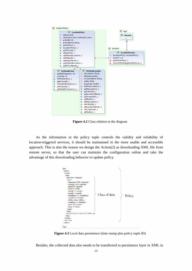
Their relation in the class diagram is shown in Fig. 4.2 below.
25
Figure 4.2 Class relation in the diagram
As the information in the policy tuple controls the validity and reliability of
location-triggered services, it should be maintained in the more usable and accessible
approach. This is also the reason we design the Action(2) as downloading XML file from
remote server, so that the user can maintain the configuration online and take the
advantage of this downloading behavior to update policy.
Figure 4.3 Local data persistence (time stamp plus policy tuple ID)
Besides, the collected data also needs to be transferred to persistence layer in XML in

26
Fig. 4.3. The time stamp is recorded to support the possible sort and check up operation in
the remote server.
4.3 Location-Triggered Process Modeling
In the Android application, the service should monitor the user’s location with certain
strategy and identify the actual relation between current physical location and interested
destinations. And the background service will check how to perform actions with the
policy.
Based on the triggering process analysis in the last chapter, the application should
first position the user. That is an accurate coordinates gained by GPS at every time point t.
Then the application will request the policy to fetch all the coordinates of the interested
places of target and compare them with the GPS acquired coordinates, and trigger actions
if needed. We model the process in the swimming lane diagram Fig. 4.4.
Monitor Based On StrategyUser Location Update
Policy
规则元组Location-Policy
DefinedLocations
Trigger actions
CurrentLocation
Coordinates
Not yet arrived Inside targets
DefinedActions
Location Judgement
Not yet triggered
Triggered alreadyInterval Time
Request GPS update
Figure 4.4 General location-triggered application monitoring work flow model
Based on the location judgemental results in the above work flow, there will be
several situations as illustrated here:
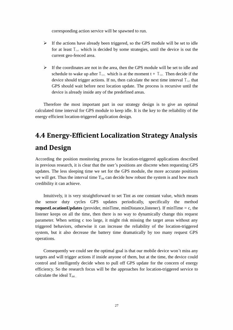
If the coordinates are in the area, then the action ID will be looked up and
27
corresponding action service will be spawned to run.
If the actions have already been triggered, so the GPS module will be set to idle
for at least Tint which is decided by some strategies, until the device is out the
current geo-fenced area.
If the coordinates are not in the area, then the GPS module will be set to idle and
schedule to wake up after Tint, which is at the moment t + Tint. Then decide if the
device should trigger actions. If no, then calculate the next time interval Tint that
GPS should wait before next location update. The process is recursive until the
device is already inside any of the predefined areas.
Therefore the most important part in our strategy design is to give an optimal
calculated time interval for GPS module to keep idle. It is the key to the reliability of the
energy efficient location-triggered application design.
4.4 Energy-Efficient Localization Strategy Analysis
and Design
According the position monitoring process for location-triggered applications described
in previous research, it is clear that the user’s positions are discrete when requesting GPS
updates. The less sleeping time we set for the GPS module, the more accurate positions
we will get. Thus the interval time Tint can decide how robust the system is and how much
credibility it can achieve.
Intuitively, it is very straightforward to set Tint as one constant value, which means
the sensor duty cycles GPS updates periodically, specifically the method
requestLocationUpdates (provider, minTime, minDistance,listener). If minTime = c, the
listener keeps on all the time, then there is no way to dynamically change this request
parameter. When setting c too large, it might risk missing the target areas without any
triggered behaviors, otherwise it can increase the reliability of the location-triggered
system, but it also decrease the battery time dramatically by too many request GPS
operations.
Consequently we could see the optimal goal is that our mobile device won’t miss any
targets and will trigger actions if inside anyone of them, but at the time, the device could
control and intelligently decide when to pull off GPS update for the concern of energy
efficiency. So the research focus will be the approaches for location-triggered service to
calculate the ideal Tint .

28
4.4.1 GPS Update Interval Estimation Analysis
We model the location and movement of user as follows. We consider a user at point
a moving along the vector l at a speed of v (m/s). The circle centered at point b with
radius r is the closest geo-fenced area to the user. The distance between a and b is d and
. The angle denotes the angle between vector l (orientation) and the shortest path
between a and b (bearing), . Fig. 4.5 illustrates the above descriptions as
follows:
a
bd
r
Figure 4.5 The user is heading to the geo-fenced area with center point b and radius r
Suppose that the user is moving through the geo-fenced area, which means the
elongation line of vector l will certainly cross the area at point D first, as shown in Fig.
4.6. In such cases,
.
a
bd r
D
B
Ax
Figure 4.6 The user is going to walking through the geo-fenced area
Let x be the length of AD. Based on the Law of Cosines (4.1), we easily obtain the
length of AD in the triangle ABD.
(4.1)
Then we can obtain x by
(4.2)

29
We estimate the interval t which the system needs to keep idle before next
power-intensive location update operation by calling the GPS considering the following
cases:
Case I: When the condition is met,we will take the minimal x
to calculate t because the system will trigger action once the user enters geo-fenced area.
(
) (4.3)
Case II: When the conditions and are met,user
is approaching the predefined geo-fenced area. However x is unsolvable, which means
there is no existence of such a triangle because the actual trajectory cannot go through the
area of interest. The elongation line of the circle radius can only cross the trajectory
outside the area, as Fig. 4.7 shows below.
a
bd r
B
A
Figure 4.7 The user is approaching but not going through
Case III: When the conditions and
are met, the
user is not heading to the geo-fenced area, as Fig. 4.8 shows below.
a
bd r
B
A
Figure 4.8 The user is not heading to the geo-fenced area
If the user’s speed is with the range of [m,n] (km/h), then the earliest time t for the

30
user to reach the geo-fenced area occurs in case I, where t =
. In
order to deploy the design in our practical application, we discuss the real-world
application mobility possibility based on the previous three different situations. Normally
if the user is approaching one predefined area without a vehicle, the normal speed of
walking is 5km/h and 15km/h for running or bicycling. If the GPS sensor is detecting the
moving speed is v at some certain point, then the user is unlikely to travel at 3 times
faster than v later on. This means that in the actual application of location-triggered
service, the GPS interval time shouldn’t be less than the Tint calculated in the formula
(4.4), otherwise the system will face risk missing the predefined triggered areas, which
will consequently leads the failure of such location-triggered systems.
Tint
(4.4)
where v’= 3v is the maximum moving speed of the user.
According to the formula above, if the system monitors that the user’s moving speed
is v (v > 0), then the system is expected the next GPS sampling when the user has moved
about 1/3 of the way to the fenced area because the user’s speed has been constrained to
walking and bicycling, therefore even the user speeds up to 15km/h, it is slower than 3v.
4.4.2 Orientation, Bearing and
When the system satisfies the condition
, GPS should be ready to
request location update, and no matter at what speed, as long as the device is not moving
towards the interested locations, such mobility should always not be treated as something
that will possibly trigger actions. Combined with the analysis in the last section, it is very
important to know the device’s orientation because it will affect on the following
questions:
Should the service invoke GPS for location updates?
When should the service invoke GPS for location updates?
This part will describe the orientation, bearing and so we can know more clearing
about their coordination work flow in the design work later.
The azimuth is the angle formed between magnetic north and a line from the
observer to a point of interest projected on the same plane [27]. On the Android platform
using accelerometers and magnetic field sensor could help us to gain this value. It is
important to call the geographic library to calculate the Rotation Matrix and Inclination
Matrix, and then get the matrix of azimuth.
The matrix of azimuth contains actually angles that are calculated from the line
31
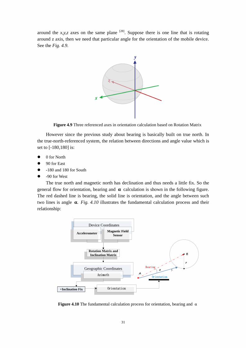
around the x,y,z axes on the same plane [28]. Suppose there is one line that is rotating
around z axis, then we need that particular angle for the orientation of the mobile device.
See the Fig. 4.9.
Figure 4.9 Three referenced axes in orientation calculation based on Rotation Matrix
However since the previous study about bearing is basically built on true north. In
the true-north-referenced system, the relation between directions and angle value which is
set to [-180,180] is:
0 for North
90 for East
-180 and 180 for South
-90 for West
The true north and magnetic north has declination and thus needs a little fix. So the
general flow for orientation, bearing and calculation is shown in the following figure.
The red dashed line is bearing, the solid line is orientation, and the angle between such
two lines is angle Fig. 4.10 illustrates the fundamental calculation process and their
relationship:
a
rBearing
B
A
Geographic Coordinates
Device Coordinates
AccelerometerMagnetic Field
Sensor
+Inclination Fix
Rotation Matrix and
Inclination Matrix
Azimuth
Orientation
Orientation
Figure 4.10 The fundamental calculation process for orientation, bearing and

32
4.4.3 Location Estimation Process
Relying on GPS update to gain geographic information cost a lot of energy. Plus there is
no need to monitor the user’s status so accurately all the way to the destinations. Other
on-device sensors can gain the data with less delay and energy consumption, so this
section will discuss the approach to estimate the device’s position with accelerometer and
magnetic field sensor, instead of performing GPS update all the time.
We estimate the location of user based on each orientation reading. If the user
keeps the same moving speed and orientation, the distance d that he will have moved
in a small time interval , will be . We can obtain the orientation in
radian of the user with the accelerometer and magnetic field sensor on the smartphone
periodically, based on the calculation process described in Chapter 4.4.2, where
. For example, if the user is moving to the North. It is equal to
and - for East and West.
Let (x, y) be the latitude and longitude from the latest GPS reading. We convert the
reading to (μ, γ) in radian by μ = x π / 180 and γ = y π / 180. Given the radius of earth
R = 6378.1 km, we calculate the new location, (x’, y’), of the user after time by
(4.5)
(4.6)
We can then estimate the new location of the user without calling the GPS. Based
on this newly estimated location, we can calculate the new time interval Tint for
calling the GPS. Theoretically since the first time we get the accurate GPS reading P0, as
long as the user keeps velocity constant and no acquisition delay, then all the estimation
positions Pi after every interval Ts forms the set, given Ts 0:
where n is the total estimation number. This set represents the trajectory of the device.
Location-triggered applications should have separate threads to handle estimation so the
data could be automatically pumped into the physical historical position chain without
ANR (Application Not Responding) problem. In this case the background service takes
advantage of one new thread to function as a timer to estimate next orientation. The fixed
interval time between each timer sparkles is we discuss above. Since accelerometer
consumes much less energy than GPS sampling and knowing about moving orientation is
so important in our design pattern for scheduling GPS update, we can set to the
expected time to go through the geo-fenced area time, for example 60 seconds in the

33
usual cases. The estimation coordinates pumped into the Position Records Chain will be
used to re-schedule the more precise GPS update when the actual situation belongs to
case I in Chapter 4.4.1. The time sequence diagram of presenting the procedure from
different modules is in the Fig. 4.11 below.
PositionRecordsChain Accelerometer
Request Orientation
Timer
New Timer
Provide Orientation
Request to calculate next
Provide Orientation
Request to calculate next
GPS
Request GPS update
Accurate Coordinates
Provide Orientation
… …
Request to calculate next
Provide Orientation
Exceed threshold
Results
Suspend Estimation Timer
Continue Timer
Figure 4.11 Time sequence diagram to illustrate tasks among different sensing modules
location estimation
We can lower the frequency to request GPS updates but we must have threshold
mechanism to keep the system on track, i.e. keeping it alert to current estimated position
and moving intention. For example, we might use the estimation to reschedule GPS
update but we can still keep the “old” scheduled GPS time as the “compulsory run GPS
moment” if there’s no update so far yet. Besides, in Chapter 4.4.4 we discuss one
possibility how we can guarantee the estimation is not out of control. In such design,
applications should be able to intelligently trade accuracy for energy consumption on the
way to approach, but energy consumption for accuracy when getting much closer to the
predefined areas. From this perspective, the GPS interval time Tint is adaptive to the
device’s status, which is essential for general location-triggered application design.

34
4.4.4 Estimation Control Mechanism in Multiple Triggered Areas
Estimation based on monitoring position points or trajectory [17][20], needs to have control
mechanism to adjust the estimated results and actual results, either using the angle change
or the distance from current position and estimated position as the threshold.
Location-triggered applications need to consider more than conventional LBS because
there are possible multiple geo-fenced areas to take into account. In other words, it is not
the accurate current position that the service cares but the relation between the position
and the desired places. This paper introduces the approach to use policy tuples to observe
that relation, as one important part of the control mechanism.
a
l
BA
b
O
C
Figure 4.12 Estimation Control Management in Multiple Geo-fenced Areas
Fig. 4.12 above shows one deficiency of estimation work in the case of multiple
triggered areas. Suppose the solid arrow represents the moving trajectory. Once the user
starts to move then request GPS update. Soon the user reaches point A and is detected to
move towards circle b. If the user moves at a low speed, then the calculated interval time
before next GPS update will be relatively long for energy concern. The system will be
convinced that the device is at point C when next estimation occurs. However, the user is
actually turning right after point A. So by the time the device is in fact at Point B but the
location-triggered service knows nothing about that. Based on formula (4.4), the
imminent orientation detection at Point C will point out that the device can’t go through
either circle a or b. What’s worse, the interval time we set is long so the system can’t get
updated in a short while, which leads to the failure of this system.
The reason that causes the above failure lies in the misjudgment about the intended

35
geo-fenced area. The estimation relies on the orientation but it is far from enough. In
location-triggered applications, different triggered areas should have different weights
which are related to the distance to these areas. The system should always give priority to
the most interested area (IA) which is the closest geo-fenced area.
In one practical solution, the update of a user’s position can avoid such misjudgment
but on the contrary, can get benefit from the geometrical composition of these multiple
triggered areas. See the Fig. 4.13.
r1
r2
r3
A
B
Cl1
l3
l2
X0
X1
X2
X3
ω
Zone 1
Zone 2
Figure 4.13 Perpendicular bisector usage in estimation control mechanism
In the above figure, we have set three geo-fenced areas A, B and C for one
location-triggered application, the solid arrow represents the actual moving trajectory.
l1,l2,l3 are the perpendicular bisectors of AC, AB and BC respectively. When the user is
entering Zone 1, it is actually leaving IA. The deficiency will occur as previous discussed
if it crosses the line l1 and no location update. The mechanism should observe the
intention that the user is departing from IA and then set new IA that is area A. To make
sure the IA has been changed it is a good time to sparkle GPS update. When the user is
departing from Zone 1 and heading to Zone 2, the control mechanism works again to
trigger update the position. In such way the system is not restricted with the preset
interval Tint for update operation, but adaptively forced to update when the IA has been
reset. In other words, “the user has changed his intention”.
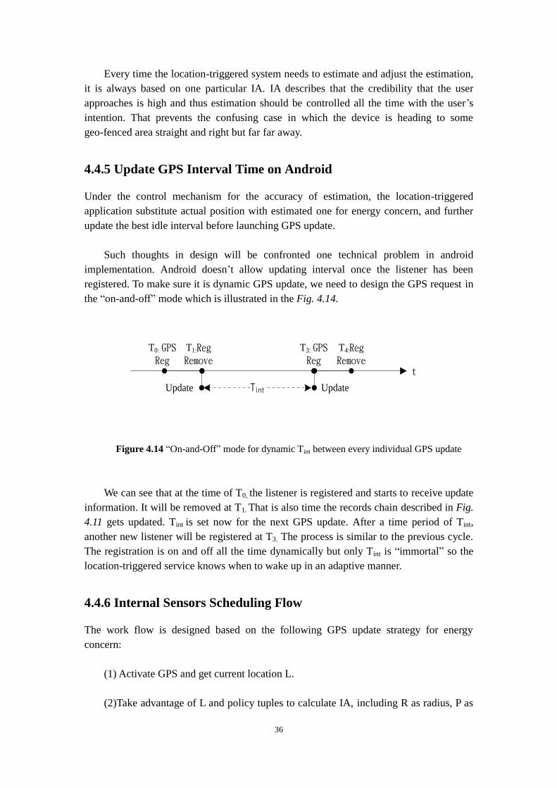
36
Every time the location-triggered system needs to estimate and adjust the estimation,
it is always based on one particular IA. IA describes that the credibility that the user
approaches is high and thus estimation should be controlled all the time with the user’s
intention. That prevents the confusing case in which the device is heading to some
geo-fenced area straight and right but far far away.
4.4.5 Update GPS Interval Time on Android
Under the control mechanism for the accuracy of estimation, the location-triggered
application substitute actual position with estimated one for energy concern, and further
update the best idle interval before launching GPS update.
Such thoughts in design will be confronted one technical problem in android
implementation. Android doesn’t allow updating interval once the listener has been
registered. To make sure it is dynamic GPS update, we need to design the GPS request in
the “on-and-off” mode which is illustrated in the Fig. 4.14.
T0: GPS Reg
T1:Reg Remove
T3: GPS Reg
T4:Reg Remove
TintUpdate Update
t
Figure 4.14 “On-and-Off” mode for dynamic Tint between every individual GPS update
We can see that at the time of T0, the listener is registered and starts to receive update
information. It will be removed at T1. That is also time the records chain described in Fig.
4.11 gets updated. Tint is set now for the next GPS update. After a time period of Tint,
another new listener will be registered at T3. The process is similar to the previous cycle.
The registration is on and off all the time dynamically but only Tint is “immortal” so the
location-triggered service knows when to wake up in an adaptive manner.
4.4.6 Internal Sensors Scheduling Flow
The work flow is designed based on the following GPS update strategy for energy
concern:
(1) Activate GPS and get current location L.
(2)Take advantage of L and policy tuples to calculate IA, including R as radius, P as
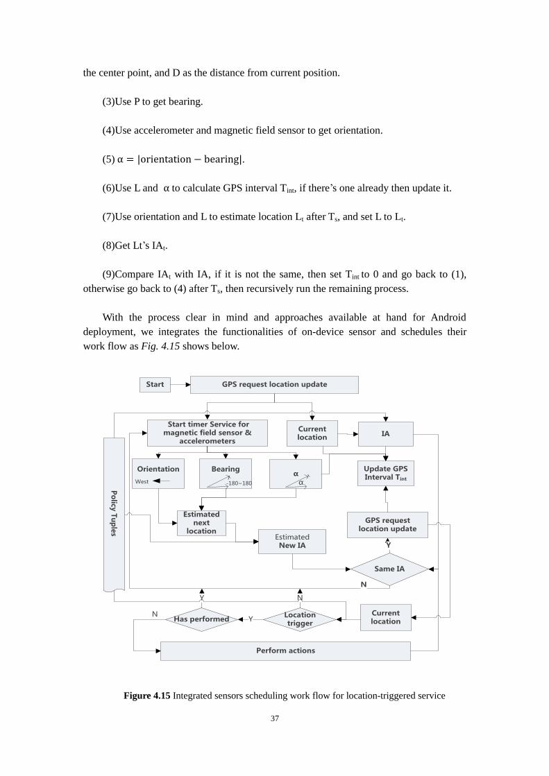
37
the center point, and D as the distance from current position.
(3)Use P to get bearing.
(4)Use accelerometer and magnetic field sensor to get orientation.
(5) .
(6)Use L and to calculate GPS interval Tint, if there’s one already then update it.
(7)Use orientation and L to estimate location Lt after Ts, and set L to Lt.
(8)Get Lt’s IAt.
(9)Compare IAt with IA, if it is not the same, then set Tint to 0 and go back to (1),
otherwise go back to (4) after Ts, then recursively run the remaining process.
With the process clear in mind and approaches available at hand for Android
deployment, we integrates the functionalities of on-device sensor and schedules their
work flow as Fig. 4.15 shows below.
Orientation
Start
Current location
Po
licy T
up
les
Start timer Service for magnetic field sensor &
accelerometers
GPS request location update
West
Bearing
-180~180
αα
Update GPSInterval Tint
Estimated next
location
IA
Estimated New IA
Same IA
Y
N
GPS request location update
Current location
Location trigger
Has performed YN
Perform actions
NY
Figure 4.15 Integrated sensors scheduling work flow for location-triggered service

38
4.5 Summary
Followed by the location-triggered service pattern and policy tuple concept built in the
last chapter, this chapter gives action design instance and policy design in Android
platform, models the location-triggered estimation process, and delves deep in location
update strategy, e.g. the estimation algorithm and co-working coordination flow for
on-device sensors to conserve energy for location-triggered applications. The content
covers the core guidelines for designing one general location-triggered application on
smartphones.
In the discussion, we are not only studying about the process of location-triggered
service, but also identify the constraints in designing energy-efficient location-triggered
applications in general, and this is where the estimation strategy and control mechanism
are stemming from. Combined with Android characteristics, we define on-and-off mode
to conserve energy and make GPS sleep as long as possible while keep it “alert”. The
working flow diagram given at last gives an integrated view of the strategies discussed
early and valid reference model in designing one concrete location-triggered application.
This is also for the integrated framework design for multiple location-triggered
applications in next chapter.

39
Chapter 5. Location-Triggered Applications
Middleware and Integrated Framework Design
This chapter designs the middleware used in the location-triggered applications to make
the mobile application environment as an integrated energy-efficient framework. Based
on the single location-triggered application design principles, the framework is intended
to provide the unified energy efficient running environment for multiple applications to
request service and conduct corresponding behaviors as needed.
5.1 Middleware Analysis and Design
5.1.1 Interval Decision Maker Algorithm
The reason we need to complete location-triggered application framework with
middleware design is the energy waste problem that multiple location-triggered
applications are confronted with caused by asynchronous resource allocation. From the
last chapter we have discussed “on-and-off” mode. However, the requests from multiple
LBS can’t be coordinated automatically by Android in this mode.
T3: GPS request update
TInt-B
AppB:
T4: GPS request update
TInt-A
GPS
T1: GPS request UpdateAppA:
T2: GPS request update
t
t
Figure 5.1 Requesting GPS update from multiple location-triggered applications
In the above figure, location-triggered application AppA requests to update location
at T1 and gets the geographic information very soon. Suppose the user launches another
location-triggered application at T2, then the request will also be passed to GPS module in
the bottom layer. AppA updates its interval time to Tint-A based on the fresh GPS
information, while AppB updates its interval time to Tint-B based on the other fresh GPS
information. The similar situation will occur again at T3 and T4. If we set as the
absolute difference value between T1 and T2 or T3 and T4, i.e.:
| T1- T2 | (1)

40
| T3- T4 | (2)
The problem will rise if is small so that different T2 comes just right after the
removal of the AppA listener. Then the physical layer of GPS module will be called
again while the user is actually staying at the same place. The ideal update operation
should occur at T1 and T3, as indicated with the red arrows in the Fig. 5.1.
Consequently at T2 and T4 we could directly use the most recently data to decrease the
power-intensive GPS update by 50% for energy concern. Middleware is built to
coordinate the redundant GPS update operations in the cross process framework. The core
functionality is to get the requests from applications in the upper layer in real time and
decides the ideal time to request GPS resource. We define this part as interval decision
maker, IDM.
The approach to implement IDM is to set to make the time point to time range.
The value defines how long time the previous update result can be valid for future
coming requests, which are even from other applications to reuse. In this range, all
locations data are approximated to one value. Of course it is trading data accuracy to
energy concern. Suppose that Lt means the GPS reading result at time t, the system
obtains location update result C at t0, and there exists one to make Lt belong to the
set defined in formula (5.1), such is counted as the GPS valid time of position data
C.
Set(Lt’) = { Lt’= C | t’ [t0, t0+ ) and Lt0 = C} (5.1)
In the design process of IDM, could be updated as the estimated arrival time
changes. That makes sense because when the user is getting closer to the geo-fenced
area, then should be smaller to keep the system alert enough (time to trade energy
for accuracy at this time). In order to keep the simplicity of the middleware design,
we assume it is a constant value in our following algorithm design.
In the single application, GPS interval time could be adjusted as the last chapter
describes. App0 duty cycles estimation periodically (T= ) and such estimation will
generate estimated interval time in an array [Tint0|t0, Tint0|t1, Tint0|t2…], shown in the Fig.
5.2.
TInt0|t0
△t
TInt0|t1 TInt0|t2...
t0 t1 t2t
Figure 5.2 Interval array values distribution on the dimension of time within one
location-triggered application

41
In the multiple application scenario, at each time point ti (i = 0, 1, 2,..k,..) all running
location-triggered applications will calculate the GPS interval based on its individual IA.
If we treat the location-triggered application number as the second dimension, then IDM
matrix could be formed in the Fig. 5.3 below. This matrix is the selection pool for IDM to
calculate. IDM is responsible to select the most ideal interval for all running
location-triggered applications.
TInt0|t0
...
△t
TInt1|t0
TInt2|t0
TInt3|t0
TInt0|t1
TInt1|t1
TInt2|t1
TInt3|t1
TInt0|t2
TInt1|t2
...t0 t1 t2
t
Apps
Figure 5.3 IDM Matrix
In the matrix, for example, int1|t2 means it’s at time t2 and the interval calculation
request is from application 1, so Tint1|t2 means the calculated interval value (calculation
method can be referred to Chapter 4.4) for application 1 at t2.
Suppose we have an array T[]. The size is the number of the applications. This data
structure will store the scheduled time to request GPS update in physical layer for each
location-triggered application. In order to have a dynamic preset-request time while avoid
repeatedly request GPS during small interval, IDM will be responsible to maintain this
array, coordinating their GPS request schedule on behalf of each application for energy
concern.
This array represents different applications’ scheduled time, i.e., the value of T[i]
represents the time for location-triggered application i to request GPS update. It can be
updated periodically according to the settings of the timer (at t0,t1,t2,…). The initial state
for this array will be all zero. Once the scheduled GPS update has happened as the
application i arranged, the value of T[i] will be set to zero again. Considering setting GPS
result valid time to a positive real number c in the formula (5.1), for any two
location-triggered applications X and Y with scheduled update time T[X] and T[Y], we
can define application X’s scheduled time T[X] is inside the GPS result valid range of
T[Y] if it satisfies:
T[X] [T[Y], T[Y] + c) (5.2)

42
It is also the same vice versa, i.e. Y’s scheduled time T[Y] is inside the GPS result
valid range of T[X] if T[Y] [T[X], T[X] + c).
At the time of tj (j = 0,1,2…) IDM will receive the portrait line interval values
from each application, i.e. Tint0|tj, Tint1|tj, Tint2|tj … Let Tx be the scheduled time value
for GPS update of any application denoted by application X. Seemingly Tx should be
current time value tj plus the interval value. However IDM will calculate to maintain
each application’s scheduled time T[X] based on the current time and all applications’
individual planning interval value. IDM will update this array T[] to avoid any
application’s scheduled time is inside some other applications’ GPS result valid range.
The process is described in the following algorithm:
Initialize Applications’ scheduled time Array T[] with 0
Do While IDM receives interval values (Tint0|t, Tint1|t, Tint2|t…)from each application scheduling request
Do Until every application’s request with positive number has been handled
For every application X:
Set new scheduled time Tx To current time tj plus Tintx|t
Case application X’s array value hasn’t been set (equal to 0)
If Tx is inside GPS result valid range of any application Y’s scheduled time
Set T[X] To T[Y]
Else
Set T[X] To Tx
End If
End Case
Case application X’s array value has been set
If Tx is smaller than T[X]
If Tx is inside GPS result valid range of any application Z’s scheduled time
Set T[X] To T[Z]
Else
Do While There exists any application W that satisfies T[W] is inside GPS result valid range of Tx
Set T[W] To Tx
End Do
Set T[X] to Tx
End If
Else
Keep original scheduled time in Array T[]
End If
End Case
End Do
End Do
Figure 5.4 The algorithm for IDM to maintain GPS resource allocation
All location-triggered applications are managed by IDM to maintain their GPS
interval matrix for cross process coordination and integration. In the middleware all the

43
GPS requests are coordinated so that it is impossible for applications to directly request
resource at bottom layer at a very frequent pace. All resource allocation is scheduled by
IDM and IDM is doing the selection based on the matrix which is generated from the
upper layer applications. IDM shapes the array based on the idea that all applications’
scheduled time should not be inside any other application’s GPS result valid range.
5.1.2 Intrinsic Data Generator in the Framework
The middleware is complete without support from IDG (Intrinsic Data Generator). IDG is
for the qualities which are not related to the number of location-triggered applications, the
mechanism to schedule accelerometers, the uncertainty of location-triggered policy tuples
or the GPS interval calculation algorithm (currently we use estimation). IDG is only
responsible for the user intrinsic data because of the uniqueness of the device. That refers
the user’s speed, orientation, current position, etc.
Location-triggered App1
GPS reg
Tint1IDM
Location-triggered App2
Policy
Tuple
Orientation
vt=i
Current
position:L0|t=i
Next position:
Lj = Est(t, v,α,Lj -1)
IA:LInt
F(α,vt=i1,LInt,L0|t=i1) G(α,vt=i2,LInt,L0|t=i2)
IDG
unreg unreg
Tint2
GPS Module
notify
Tint1 Tint2
Policy
Tuple
IA:LInt
GPS reg
update
Bearing + α
Accelerometer
Magnetic Field Sensor
Pumped
By TimerGPS reg
(Programme Independent)
(P
rog
ram
me C
oo
rdin
atio
n)
Figure 5.5 IDM and IDG in the integrated framework
In the Fig. 5.5 we can see the framework has identified the program independent
components. Bearing and are always relying on IA, and IA is always relying on the
individual policy tuples of each program. However, the user’s speed and current position,

44
no matter it is estimated by some strategies or accurately acquired from GPS, are always
the intrinsic qualities that can be shared among different applications. Thus we intend to
put accelerometers and magnetic field sensor at the bottom layer as the “driver”,
periodically pumping data to upper applications. The information size can be relatively
small but also is communication across processes, so we could refer to cheap and easy
“broadcast intent” approach which has been discussed in Chapter 2.3.3 to fulfill this
purpose.
What’s more we even allow different programs to have their own algorithm to
calculate GPS interval, as we use F and G two totally different functions to calculate their
corresponding interval values. The coordination work will be handled by IDM and further
request will be passed to lowest layer in this application framework.
To be exact and precise, the input of IDG has:
(1) Current updated location information from IDM
(2) The sensing data from accelerometers and magnetic field sensor
Output data has:
(1) Current location coordinates
(2) Speed
(3) Orientation
(4) Tint calculated by (2) (3) (4)
The Interval value then will be put into IDM Matrix.
5.2 Framework Implementation Hierarchy and
Design on Android
From Fig. 5.5 we understand that middleware should be located below the application
business layer. This middleware is independent from the upper business flow about
triggered actions and policy tuples, but the data must be coordinated in this layer for IPC.
Suppose we have location-triggered AppA and AppB, and they are running in
separate process A and process B. Once they want to request GPS update and set interval,
the messages will be sent to middleware in process C. On the contrary, the reply from
middleware can be sent back through AIDL interfaces, which are briefly discussed in

45
Chapter 2.3.3. Meanwhile accelerometer can, on the one hand, store the orientation
information in the middleware for further process, and on the other hand can broadcast
intents to upper layer application as the pump. This is also a great advantage to implement
because multiple location-triggered applications can synchronize their on-device sensors
which cost much less energy than GPS.
Process A Process B
C kernel Driver (Data Exchage)
Binder
Client 1:AppA Client 2:AppB
IDGIDM
MiddlewareProcess C
Reply
(AIDL)Reply
(AIDL)
Accelerometer Broadcast
Request
Figure 5.6 Framework Implementation Hierarchy
In short the middleware is interacting with location-triggered applications in the
tradition Client/Server pattern. Request from clients and response from the server, the
pattern model is the basic implementation for IPC on Android, as Fig. 5.6 illustrated
above. In detail, we can also see how the data are implementing communication across
processes in the lower layer. Through the Binder Framework studied earlier, the data can
be exchanged in the C kernel driver.
So now it’s time to shift our design work to the interface implementation of the
middleware. Public common interfaces should be incorporated nice and well in the
interfaces, for example, the method we need to allocate resources for GPS update. In our
prototype we can design the interface with AIDL.
This AIDL interface named as ILocationCoordinator contains method of
requestGPSUpdate in the Fig. 5.7 below, and Clients AppA and AppB can request the
service without distinguishing it is local or remote. Middleware implementation provides
such essential remote service in fact, but the clients are calling as they call local methods.
Another reason we use AIDL is also because it can alleviate the development work of the
programmers. As they develop new location-triggered applications based on their

46
individual business requirements, they all can merely import the AIDL interfaces in the
form of Java JAR package and call API as they did for conventional other LBS.
Programmers don’t have to care about implementation details in the lower layer but just
their business.
interface ILocationCoordinator
{
...
List<String> requestGPSUpdate(String str);
...
}
Figure 5.7 AIDL interface definition snippet in the middleware
The detailed implementation for the requestGPSUpdate will be in the
com.location.ipc.Stub Class. This class implements all the AIDL interfaces in the server
side we define for any client service or component to call. To make it public we need to
publish these services. Stub Class has an inline Class which is Proxy. Both of them are
inherited from Binder Class. MyBinder Class is iheritated from com.location.ipc.Stub and
overload the GPS request service and this enables the communication between clients and
the server. For example, AppA as one client location-triggered application is built as one
service. After this service is started normally, then it will try to bind service with the
server through a proxy which is doing the actual delegation work. The proxy and stub
serve the most important tasks for IPC.
Stub
Proxy
AppB
bindService()
Service
Call GPS ModuleAppA
Figure 5.8 Proxy and Stub functionalities in the IPC framework for multiple
location-triggered applications
Then it will locate the Stub Class and delegate the remote service to the local AIDL
interface mIBinder. Therefore the remote service of the middleware is started passively

47
without any human interaction and the clients are able to request the server once the
connection is done. The delegation approach is presented in Fig. 5.9.
private ILocationCoordinator mIBinder;Public void onServiceConnected(ComponentName name, Ibinder service) {
mIBinder = ILocationCoordinator.Stub.asInterface(service); ... mIBinder.requestGPSUpdate("Message from ClientA"); ...
}
Figure 5.9 AIDL interface delegation from remote process to local process
Overall the framework hierarchy is presented in Fig. 5.10.
Connect and Call
Overide
Figure 5.10 Location-triggered application framework design using AppA as one client
application and LocationManagerService as the coordinator server

48
We define the middleware as one remote service called LocationManagerService
running in Process C. It is always in the background and the core of integrated framework.
As AppA and AppB are functioning the same way in the hierarchy, for the simplicity, we
skip AppB in the above relation diagram in our IPC design work of the location-triggered
application framework on Android.
One more thing to care in the multi-process framework is to make sure the
synchronization among these processes. For example, if one location-triggered
application starts to request GPS resource then we need to protect the resources and
guarantee the asynchronous visits won’t cause dead lock or similar issues. In our
approach, once AppA has requested the server as the first one in the queue, all resources
can only be available once IDM has made the decision. The reason we implement like
this is due to:
(1) Guarantee threads safety and synchronization.
(2) Guarantee the data for IDG is the freshest.
5.3 Summary
Followed by the location-triggered application design and strategy scheduling in the
last chapter, this chapter delves deep into the integrated application framework design for
the energy efficiency. The core part is the middleware design and functionality analysis,
including its role among multiple location-triggered applications. IDM IS helping to
handle the requests from individual location-triggered applications in upper layer, while
IDG can create the shared platform among multiple processes about the user’s intrinsic
data.
This chapter also presents the method to build the integrated framework on Android
platform. Traditional C/S model is referenced and binder framework from Android is
implemented in the actual work. The outcome is that multiple location-triggered
applications can have their rights to define business flow without any constraints from the
middleware but the power-intensive resources on the mobile phone are allocated in the
synchronized approach. Therefore it boosts the energy efficiency while maintaining the
flexibility and accuracy of this application framework in general.

49
Chapter 6. Location-Triggered Application and
Framework Evaluation
This chapter will deploy the application framework implementation described in last
chapter on Android smartphones and conduct the experiments in the real-world scenarios.
It evaluates the energy consumption and expensive operation on the location-triggered
applications compared with traditional periodic GPS update pattern as well as the
robustness and efficiency from the implemented integrated application framework.
6.1 Experiment Objects
6.1.1 Location-Triggered Application Instances
Location-triggered applications here mean the application set defined in Chapter 3
that has independent location-triggered policies and business goals. They are located in
the upper layer of the application framework and can be developed by different software
manufactures, and interact with middleware in Client/Server model. The middleware
coordinates the requests from various clients for energy concern by providing the public
data exchange mechanism and best GPS interval selection strategy. In our experiments we
defined two customized application App1 and App2. The accelerometer cycle time is set
to 60 seconds, the same as of IDM.
App1 : Uppsala Bus Stop Reminder
The business goal of the app is to remind users about bus stop information in the
city of Uppsala. See Fig. 6.1 below.
Figure 6.1 App1: Uppsala Bus Stop Reminder
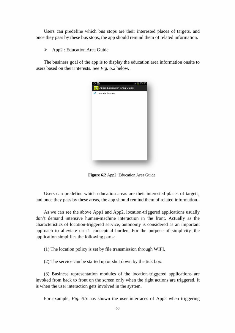
50
Users can predefine which bus stops are their interested places of targets, and
once they pass by these bus stops, the app should remind them of related information.
App2 : Education Area Guide
The business goal of the app is to display the education area information onsite to
users based on their interests. See Fig. 6.2 below.
Figure 6.2 App2: Education Area Guide
Users can predefine which education areas are their interested places of targets,
and once they pass by these areas, the app should remind them of related information.
As we can see the above App1 and App2, location-triggered applications usually
don’t demand intensive human-machine interaction in the front. Actually as the
characteristics of location-triggered service, autonomy is considered as an important
approach to alleviate user’s conceptual burden. For the purpose of simplicity, the
application simplifies the following parts:
(1) The location policy is set by file transmission through WIFI.
(2) The service can be started up or shut down by the tick box.
(3) Business representation modules of the location-triggered applications are
invoked from back to front on the screen only when the right actions are triggered. It
is when the user interaction gets involved in the system.
For example, Fig. 6.3 has shown the user interfaces of App2 when triggering

51
actions and receiving remind from the service. The bar notifications are in the ellipse.
Figure 6.3 App2: Notification user interfaces when triggering events around BMC area
The visual notification is also with the sound to mind the user. If the user clicks
the notification bar and check the information of triggered areas, the application will
automatically be redirected to the corresponding activities. In this case when the user
clicks the notification bar in Fig 6.3, the front will show the information of BMC as
displayed below. This presents the high customization ability of the application
framework.
Figure 6.4 BMC introduction displayed once the user clicks the notification bar

52
In order to decrease the interference from triggering action itself on battery
monitoring, the experiments will conduct the same remind formality on different
location-triggered application: vibrating, sound and screen display. The user has the
right to choose to check the detailed information or not and by default the user doesn’t
take any continuous actions.
6.1.2 Location-Triggered Application Manager
Location-triggered application manager (LTAM) is just the presentation form of
the middleware component in the whole framework. It is actually working as one
service in the background and coordinates the behaviors from different application
“clients” silently. The simple UI is shown in Fig. 6.5 below.
Figure 6.5 Location Triggered Application Manager
The figure in the top left corner represents the orientation value in real time. LTAM
implements all the AIDL interfaces and is exported as the Jar packet. Therefore client
location-triggered applications can only focus their business rules and leave much of the
energy efficiency work to the middleware in the underlying layer. Users also don’t have
to upgrade the firmware to some specific version.
6.1.3 Periodic Location-Detection Application
We also implement the periodic location-detection application PeriodicApp1 and
PeriodicApp2 as the control group. PeriodicApp1 and PeriodicApp2 are taking
location-triggered service pattern but they don’t use the sensor strategy and
energy-efficient framework discussed in the paper to obtain the adaptive interval. On the
contrary, they only judge the user’s location by periodical GPS update operations. The

53
front UI is the same as App1 and App2.
6.2 Location-Triggered Areas Description
We need to define the real-world scenarios for the sake of energy consumption evaluation
and various business goals in our experiments. The radius of all geo-fenced area is set to
50 meters.
Case 1:
Experiment Group: App1
Control Group: PeriodicApp1
Business Goal: Uppsala Bus Stop Reminder. The auto-triggered interested zones are
only set to:
(1) Grindstugan Bus Stop. Latitude: 59.85612, Longitude: 17.617285
(2) Uppsala Science Park Bus Stop. Latitude: 59.843327, Longitude: 17.638711
(3) Uppsala Polacksbacken Förskola1, Latitude: 59.841942, Longitude: 17.644944. It
is flagged as the dot bubble on the right side in Fig. 6.6 below. Through anti-clockwise
rotation based on (3), we can see the Position (2) and Position (1) are flagged with yellow
dot bubbles.
Figure 6.6 App1 and PeriodicApp1 Location-triggered Areas
1 This bus stop is hypothetic for the triggered areas intersection between App1 policy and App2 policy.

54
Case 2:
Experiment Group: App2
Control Group: PeriodicApp2
Business Goal: Education Area Guide. The auto-triggered interested zones are only
set to:
(1) BMC. Latitude: 59.841559, Longitude: 17.638206
(2) Uppsala BIO. Latitude: 59.844438, Longitude: 17.638936
(3) Uppsala Polacksbacken Förskola. Latitude: 59.841942, Longitude: 17.644944. It
is flagged as the bubble without dot on the right side in Fig. 6.7 below, the same as
Position (3) in scenario 1. Through anti-clockwise rotation based on (3), we can see the
Position (2) and Position (1) are flagged with yellow bubbles without dot.
Figure 6.7 App2 and PeriodicApp2 Location-triggered Areas
6.3 Deployment Methods
In the experiments we use Galaxy SIII i9300 that has 2100mAh battery as the test bed. In
order to simulate daily scenarios and evaluate energy improvements we can gain by GPS
updates, the user will hike in the area with mobile phones and trigger actions intentionally
with the same trajectory.
The model Galaxy SIII i9300 has installed Android 4.1.4, code “Jelly Bean”. See the
Fig. 6.8 below.

55
Figure 6.8 Samsung Galaxy S III i9300 Model
The user starts the hike from the red pin in the Fig. 6.9 and follows the blue path as
the trajectory. The hike will start from red pin denoted by A and end at the blue pin
denoted by B. It is about 1.93 kilometers long for the whole hiking distance.
A
B
Figure 6.9 The hiking trajectory in traffic and satellite view
6.3.1 Testing Group
Experiment Group: App1, App2 with adaptive GPS interval strategies.
Control Group: PeriodicApp1, PeriodicApp2 with periodic duty cycle GPS update.
6.3.2 Deployment Approaches
Scenario 1:

56
This test is only for single location-triggered application scenario. We need to
evaluate how the adaptive strategy perform against periodic one based on the
same triggered cases described in Chapter 6.2, so we install App1 and
PeriodicApp1 in two smartphones, as we do this for App2 and PeriodicApp2.
Scenario 2:
This test is for multiple location-triggered applications scenarios. We need to
evaluate the energy efficiency when running multiple location-triggered
applications with LTAM on in our framework, against the situation that we don’t
use LTAM. So we install App1, App2, LTAM on one phone while only App1 and
App2 on the other phone.
6.4 Evaluation Results
Our system has logged every GPS update location during the experiment hiking process
so we will denote such places with red bubble with dots on the map. Besides, in the
strategy of energy-efficient location-triggered applications, the system also automatically
logged the estimated locations denoted by blue bubble without dots. We use the rectangle
frame to denote the actual triggering action places and green arrow to denote the ideal
triggering places.
6.4.1 Scenario 1: Single Application
App1 with adaptive GPS update interval:
10 times of GPS update, 3 times of triggering events at Grindstugan bus stop,
Uppsala Science Park bus stop and Uppsala Polacksbackens Förskola bus stop. Based on
the location estimation approach proposed in Chapter 4, there are 22 times of estimation.
All the data are presented in the Fig. 6.10 below.
Figure 6.10 App1: GPS update places, estimated places and triggered events place

57
We can discover that before arriving in the first geo-fenced area Grindstugan, the
user makes a turn and the system discover that the orientation is changing right to the
target. The change of angle makes the system to be more “alert”, in the way described
earlier in our algorithm to set interval time smaller for the imminent events. On the
contrary, when the system discovers that the orientation is not to the target area and lower
speed (walking), then it can set the GPS interval to a longer time. That’s also the reason
why we get the GPS updates in the beginning but not on the way to Förskolan.
Generally the GPS triggering is more successful than our expectation. This is also
due to the general constant speed and objective situation that two targeted area
(Grindstugan and Uppsala Science Park) are located along the straight long Dag
Hammarskjölds Vagen. It helps our calculation and estimation become more precise.
PeriodicApp1 with periodic GPS update strategy:
22 times of GPS update, 3 times of triggering events at Grindstugan bus stop,
Uppsala Science Park bus stop and Uppsala Polacksbackens Förskola bus stop. There is
no estimation behavior in the system. All the data are presented in the Fig. 6.11 below.
Figure 6.11 PeriodicApp1: GPS update places and triggered events place
The total test time is 22 minutes. App1 decreases the power-intensive GPS update
operation by 54.5% compared to PeriodicApp1.
App2 with adaptive GPS update interval:
11 times of GPS update, 3 times of triggering events at BMC, Uppsala BIO and
Uppsala Polacksbackens Förskola. Based on the location estimation approach proposed in
Chapter 4, there are 22 times of estimation. The data are denoted in the Fig. 6.12 below.

58
Figure 6.12 App2: GPS update places, estimated places and triggered events place
PeriodicApp2 with periodic GPS update strategy:
22 times of GPS update, 3 times of triggering events at BMC, Uppsala BIO and
Uppsala Polacksbackens Förskola. There is no estimation behavior in the system. All the
data are presented in the Fig. 6.13 below.
Figure 6.13 PeriodicApp2: GPS update places and triggered events place
The total test time is 22 minutes. App2 decreases the power-intensive GPS update
operation by 50% compared to PeriodicApp2. In order to see how much energy we can
save at least once adopting the adaptive location-triggered schema, we set the periodic
interval to 60 seconds in control group because it is the least GPS request frequency we
maintain while hardly miss any targets. As App1 and App2 have the exactly the same
implementation based on mechanical duty-cycling GPS, they get 22 times GPS updates
while only 10 times for App1and 11 for App2 in total 22 minutes test. Since the energy
efficiency strategy for PeriodicApp1 and PeriodicApp2 is the same and use the same
work flow but only different in sparkled places, we take the average power consumption

59
of ε(PeriodicApp1) and ε(PeriodicApp2) in battery monitor for their high similarity.
Figure 6.14 Energy consumption of App1, App2 and the average consumption of
PeriodicApp1 and PeriodicApp2
We can see the blue line which stands for periodic update strategy are always
fluctuating at a high level while the red and green lines which stand for energy-efficient
update strategy have dropped to lower level in the later half the experiment. Especially on
the way to Uppsala Polacksbacken, the system in the optimized framework has done a
good job to control the GPS update. This avoids using power intensive modules when it is
not necessary. In fact it is the goal we should achieve by designing such intelligent
energy-efficient location-triggered applications to substitute the traditional user-controlled
LBS. The essential is to trade accuracy for energy when the accuracy is not critical to
trigger actions. In this experiment we have triggered all actions when it is at the right
place in 22 minutes. The standard capacity specification for Galaxy SIII battery is 2100
mAh. We calculate the battery capacity consumed in the unit of milliampere-hour(mAh)
for periodic and adaptive GPS strategy based on the following procedure:
First we record the average current per minute for the 22 minutes experiment time in
the Figure 6.14, considering other unrelated background and battery monitor service
consume 220~280 mA on the Galaxy SIII phones. Then we get the mean current by
summing it up the average monitored current in these 22 minutes and later dividing by 22.
That is 9800/22 mA. Therefore the total capacity consumed is approximately 9800/22 mA
* 22/60 hour, which is 163 mAh. This means, in the past 22 minutes, we have already run
out one "battery" that can originally release stable current of 163 mA for 1 hour
theoretically. Considering the original battery capacity specification of Galaxy III
2100mAh, we have already released 163/2100 of the total battery, which is about 7.7% of
the battery amount. In physics, the unit for the battery capacity consumed is actually
Coulomb(C) because 1mAh equals to 3.6C. So the consumed batter capacity is also equal
to 3.6 * 163 mAh, which is 588C.
For App1 and App2, the calculation is the repeating the same process. We get the

60
mean current 6700/22 mA. So the total capacity consumed is 6700/22 mA * 22/60 hour,
which is 112 mAh. The consumption is 5.3 % of the total battery capacity. So we
calculate the ratio of the conservation amount of the battery by using (7.7-5.3)/7.7%. So
we save about 30% battery power in this experiment scenario.
6.4.2 Scenario 2: Multiple Applications
App1 and App2 without LTAM:
App1 and App2 have asynchronous requests and totally different business purposes.
The LTAM is off for the whole experiment under this scenario. There are 21 times of GPS
update and 6 times of triggering event. The triggering places are Grindstugan bus stop,
BMC building, Uppsala Science Park bus stop, Uppsala Polacksbacken Förskolan (bus
stop). There are also 44 times of estimation in total, as denoted in the Fig 6.15 below.
Figure 6.15 GPS update places, estimated places and triggered events places without LTAM
App1 and App2 with LTAM:
App1 and App2 have asynchronous requests and totally different business purposes.
The LTAM is on for the whole experiment under this scenario. There are 14 times of GPS
update and 6 times of triggering event. The triggering places are Grindstugan bus stop,
BMC building, Uppsala Science Park bus stop, Uppsala Polacksbacken Förskolan (bus
stop). There are also 22 times of estimation in total, as denoted in the Fig 6.16 below.

61
Figure 6.16 GPS update places, estimated places and triggered events places with LTAM
Obviously the GPS update time has decreased to 33% when integrating with our
application framework. To better illustrate how the GPS update operation is optimized
with the coordination from the middleware, we also design the real time logging system
within such framework to get their event time stamp. One precise example would be the
here in the Fig. 6.17 below.
10s
85s
request
App1
App2
LTAM
t
t
t
t0 =18:49:06 t1 =18:51:06
t2=18:51:31
Figure 6.17 Location-triggered App1 and App2 coordination with LTAM
At time t0 which is 18:49:06, App2 sends a GPS update interval to the low layer to
intend to update location at t2 which is 18:51:31. However, App1 sends an interval plan at
t1 which is 18:51:06. It intends to update the location in 10 seconds (the moment where
the red spot stands). According to the parameter we set earlier for this experiment
and IDM calculation algorithm, LTAM adjusts the update moment for App2 to the red
spot, 15 seconds earlier. It obviously avoids redundant GPS update behavior when the
new GPS listener seems to be needed while the user is still at the place.
With LTAM the multiple business-independent location-triggered applications
have drew the capacity of 138 mAh, just 20-24% higher than the energy consumption
by single location-triggered application. Considering about 223mAh capacity drew by

62
running App1 and App2 separately without any coordination in the lower layer, the
integrated application framework helps these two independent location-triggered
applications App1 and App2 to save up to 38% energy.
6.5 Summary
This chapter describes the experiments object and experiment environments for the real
world deployment and evaluations. Then it evaluates the energy consumption and energy
expensive GPS update operation for energy efficient location-triggered applications
which are studied in Chapter 4. The performance has been compared with traditional
periodic GPS update pattern. For multiple location-triggered application, we also conduct
the experiment to test the efficiency improvement and validity of the middleware
designed in Chapter 5. In both scenarios we can prove the location-triggered application
framework and adaptive localization strategy are effective in conserving energy. Besides,
the design has been well illustrated for its high customization capability in
business-independent implementation and strong universality for general
location-triggered service design.

63
Chapter 7. Conclusion
7.1 Summary
Confronted with the low usability and high conceptual burden demand of current
user-triggered LBS and the embarrassing situation that only a few function-restricted
energy-consuming location-triggered application are available in the mainstreaming
mobile application markets, the paper has proposed approaches and framework to follow
to design the general energy-efficient location-triggered application used on Android
smartphones.
First the work analyzes the general work flow of the intelligent triggering pattern and
proposes a mapping relation between physical places and desired behaviors on the phone.
The general concept and classification of location-triggered applications are illustrated in
Chapter 3. Followed by the concept to build location-triggered service, Chapter 4
describes the general design approaches. The key part of the design is to improve the
energy efficiency of location-triggered applications, trading accuracy for energy
conservation when needed. The strategy takes advantage of the relation between its
current location and geo-fenced destinations, using low power-consuming sensors to
substitute power-intensive GPS module, coordinating their behaviors at a dynamic pace
rather than periodically duty cycling GPS update. In Chapter 5 the work extends the
single location-triggered application design approach to application framework design for
energy efficiency. Intelligent middleware is designed combined with the characteristics of
Android component development. This chapter has provided one unified framework for
business-independent location-triggered application to work together efficiently.
In the real-world deployment and system testing, the behaviors of energy-efficient
location-triggered applications and integrated application framework are well recorded
and evaluated in both single application and multiple application scenarios. The results
have verified the improved usability, higher customization capability and energy
efficiency validity of the location-triggered applications and the running platform which
are proposed to design with this paper. The contribution of this paper also lies to present a
novel energy-efficient LBS framework for future intelligent mobile LBS development in
general, as well as the broadened application scenarios for mobile cloud computing.
7.2 Future Work
Although we have made progress in improving energy efficiency for novel
location-triggered applications design, it is still far from the most energy efficient
application design in general and restricted with the following aspects:
64
(1) Current positioning tasks are primarily based on the assumption that users are
traveling on foot or by bicycle because they are among the most frequent scenarios when
users are approaching to some intended places. It needs more discussion in general once
the user has shifted the speed. Building models for user mobility will help to design more
flexible positioning strategy.
In fact, the strategy now is based on estimation and sensor substitution. It is actually
focusing on improving internal mechanism. However it is supposed to work more
effectively if the design can combine with user mobility research. To observe trajectory
history thus building mathematical model to predict the user’s next most likely desired
places, it can improve the energy efficiency from the external mechanism. For example, if
the user’s location is a sequence of random variables X1, X2, X3… The machine can learn
to build the probability distribution and calculate the probability that how likely the user
is going home at Tn+1 after previous arrival at one shop at Tn. With the Markov property,
we can get the formula (7.1) below.
P(Xn+1=Home|X1=L1,X2=L2,…,Xn = shop) = P(Xn+1 = Home | Xn = shop) (7.1)
By analyzing the state space we can estimate how likely the system might need to
turn on the GPS within the next a few hours, for instance. Combing history with current
moving tendency is the ideal positioning approach for intelligent LBS in the future
development.
(2) This framework is needed when multiple location-triggered applications are
running on the same smart phone which is the tendency of future intelligent LBS
development. However the majority of LBS are still taking conventional user-triggered
pattern and our proposed application framework didn’t merge this pattern into our
integration. The framework should be designed with more common interfaces that can
work with existing LBS compatibly.

65
References
[1] Foursqure, https://foursquare.com/. Data accessed: 2013-04-01
[2] Google Latitude, www.google.com/latitude?hl=sv. Data accessed: 2013-04-01.
[3] Dianping, http://www.dianping.com/. Data accessed: 2013-04-01.
[4] I. Constandache, S. Gaonkar, M. Sayler, R.R. Choudhury, and L.P. Cox, EnLoc:
Energy-Efficient Localization for Mobile Phones. In Proceedings of INFOCOM. 2009,
2716-2720.
[5] http://udm4.com/iPhone/Neer-973915. Data accessed: 2013-04-04.
[6] http://www.att.com/gen/press-room?pid=22675. Data accessed: 2013-04-04.
[7] http://www.apple.com/iphone/built-in-apps/. Data accessed: 2013-04-04.
[8] Axel Küpper and G. Treu. Efficient proximity and separation detection among mobile targets
for supporting location-based community services. Mobile Computing and Communications
Review, 10(3):1–12, 2006.
[9] A. Leonhardi and K. Rothermel. Protocols for updating highly accurate location information.
In A. Behcet, editor, Geographic Location in the Internet., pages 111–141. Kluwer Academic
Publishers, 2002
[10] A. Küpper. Location–based Services - Fundamentals and Operation. John Wiley & Sons,
August 2005.
[11] Kjærgaard, M. B., Langdal, J., Godsk, T. and Toftkj, T. EnTracked: energy-efficient robust
position tracking for mobile devices. In Proceedings of the 7th international conference on
Mobile systems, applications, and services. Kraków, Poland, 2009.
[12] Kjærgaard, M. B., Bhattacharya, S., Blunck, H. and Nurmi, P. Energy-efficient trajectory
tracking for mobile devices. In Proceedings of the 9th international conference on Mobile
systems, applications, and services. Bethesda, Maryland, USA, 2011.
[13] F. Abdesslem, A. Phillips, T. Henderson. Less is more:energy-efficient mobile sensing with
senseless. In Proceedings of ACM MobiHeld ’09, Barcelona, Spain, 2009
[14] Paek, J., Kim, J. and Govindan, R. Energy-efficient rate-adaptive GPS-based positioning for
smartphones. In Proceedings of the 8th international conference on Mobile systems,
applications, and services. San Francisco, California, USA, 2010.
[15] Lin, K., Kansal, A., Lymberopoulos, D. and Zhao, F. Energy-accuracy trade-off for
continuous mobile device location. In Proceedings of the 8th international conference on
Mobile systems, applications, and services. San Francisco, California, USA, 2010.
[16] X. Ma, Y. Cui, and I. Stojmenovic, Energy Efficiency on Location Based Applications in
Mobile Cloud Computing: A Survey. In Proceedings of Procedia Computer Science. 2012,
577-584.
[17] Brezmes, T., Gorricho, J.-L. and Cotrina, J. Activity Recognition from Accelerometer Data
on a Mobile Phone. In Proceedings of the Proceedings of the 10th International
Work-Conference on Artificial Neural Networks: Part II: Distributed Computing, Artificial
Intelligence, Bioinformatics, Soft Computing, and Ambient Assisted Living. Salamanca,
Spain, 2009.
[18] J. Ryder, B. Longstaff, S. Reddy, and D. Estrin. Ambulation: A tool for monitoring mobility
patterns over time using mobile phones. In Intl. Conf. Computational Science and

66
Engineering, pages 927 –931, 2009
[19] S. Tilak, V. Kolar, N. B. Abu-ghazaleh, and K. don Kang. Dynamic localization protocols for
mobile sensor networks. In Proceedings of IWSEEASN, 2005.
[20] Kim, D. H., Kim, Y., Estrin, D. and Srivastava, M. B. SensLoc: sensing everyday places and
paths using less energy. In Proceedings of the 8th ACM Conference on Embedded Networked
Sensor Systems. Zürich, Switzerland, 2010
[21] Jurdak, R., Corke, P., Dharman, D. and Salagnac, G. Adaptive GPS duty cycling and radio
ranging for energy-efficient localization. In Proceedings of the 8th ACM Conference on
Embedded Networked Sensor Systems. Zürich, Switzerland, 2010.
[22] Thiagarajan, A., L. Ravindranath, et al. Accurate, low-energy trajectory mapping for mobile
devices. Proceedings of the 8th USENIX conference on Networked systems design and
implementation. Boston, MA, USENIX Association: 20-20.
[23] Chon, Y., Talipov, E., Shin, H. and Cha, H. Mobility prediction-based smartphone energy
optimization for everyday location monitoring. In Proceedings of the 9th ACM Conference
on Embedded Networked Sensor Systems. Seattle, Washington, 2011.
[24] Zhuang, Z., Kim, K.-H. and Singh, J. P. Improving energy efficiency of location sensing on
smartphones. In Proceedings of the 8th international conference on Mobile systems,
applications, and services. San Francisco, California, USA, 2010.
[25] Elliott, D.Kaplan, Christopher, J.Hegarty, Understanding GPS principles and applications,
Springer Second Edition, ISBN-13 978-1-58053-894-7.
[26] Z1 Sensors, http://zolertia.sourceforge.net/wiki/index.php/Main_Page.
Data accessed: 2013-04-10.
[27] Azimuth, http://en.wikipedia.org/wiki/Azimuth. Data accessed: 2013-04-12.
[28] Rotation Matrix, Inclination Matrix, Orientation Calculation in Android,
http://developer.android.com/reference/android/hardware/SensorManager.html.
Data accessed: 2013-04-12.