improvements in low power, end-window, transmission-target x-ray tubes
7
IMPROVEMENTS IN LOW POWER, END-WINDOW, TRANSMISSION-TARGET X-RAY TUBES Charles Jensen, Stephen M. Elliott * , Steven D. Liddiard, A. Reyes-Mena, Melany Moras, and D. Clark Turner MOXTEK, Inc., Orem, UT USA 84057 * Thin Film Consulting, Longmont, CO USA 80501 ABSTRACT End-window transmission-target X-ray tubes are designed for very close anode-to-sample coupling for compact portable XRF instruments. Several recent improvements have been achieved to make these tubes considerably brighter, with better output stability and even smaller size and lower power consumption for handheld instrumentation. Areas of the tube that have been improved include the anode, the cathode, and the high-voltage power supply. 1) The anode can be a sputtered film on the inside of the X-ray window. Densified films of a more uniform thickness provide higher X-ray output and more consistent performance from tube to tube. 2) Changes in the anode geometry have resulted in reduced spectral contamination from metal parts in the anode. 3) The electron beam position on the anode is primarily influenced by the filament placement relative to the cathode optic. Using finite-element analysis (FEA) charged-particle beam modeling software it was possible to design an improved cathode optic with significantly better electron beam performance. This results in higher electron density on the target and a more stable beam position. 4) Finally, innovations in the high-voltage power supply have resulted in significant reductions in size and weight in this component. New power supply designs also require significantly less input power than the earlier designs. The combination of these improvements results in miniature X-ray tubes with higher flux, lower spectral contamination, more stable X-ray beams, smaller and lighter packages, and lower overall power consumption. INTRODUCTION With the miniaturization of XRF instrumentation, there has been a need for a compact, portable, battery-powered X-ray tube. In 2001 MOXTEK introduced a miniature X-ray tube designed to address the needs of handheld XRF analyzers [1,2]. This tube was designed to be a transmission-target end-window configuration in order to provide very close anode-to-sample coupling. Refer to Figure 1 for details of the interior construction of the tube. To provide for battery operation of the tube the cathode includes a thermionic filament that was designed for very low power consumption, requiring typically only 0.2 watts input power to produce 100µA of emission current. There is a circular focusing aperture to restrict the electron beam to a central cone. The anode is a sputtered film on the back of the beryllium exit window. This tube was designed to be a replacement for 109 Cd radioisotope sources commonly used in handheld XRF instruments. The 109 Cd emits primarily the Ag Kα line, so silver was chosen for the anode material. The tube has an additional advantage over the isotope sources, as it produces continuum radiation (see Figure 4 below), which is more efficient at excitation across a span of atomic numbers. Figure 1. Cross section of a transmission target X-ray tube Copyright ©JCPDS - International Centre for Diffraction Data 2004, Advances in X-ray Analysis, Volume 47. 64 ISSN 1097-0002
Transcript of improvements in low power, end-window, transmission-target x-ray tubes

IMPROVEMENTS IN LOW POWER, END-WINDOW, TRANSMISSION-TARGET X-RAY TUBES
Charles Jensen, Stephen M. Elliott*, Steven D. Liddiard, A. Reyes-Mena, Melany Moras, and D. Clark Turner
MOXTEK, Inc., Orem, UT USA 84057 *Thin Film Consulting, Longmont, CO USA 80501
ABSTRACT
End-window transmission-target X-ray tubes are designed for very close anode-to-sample coupling for compact portable XRF instruments. Several recent improvements have been achieved to make these tubes considerably brighter, with better output stability and even smaller size and lower power consumption for handheld instrumentation. Areas of the tube that have been improved include the anode, the cathode, and the high-voltage power supply. 1) The anode can be a sputtered film on the inside of the X-ray window. Densified films of a more uniform thickness provide higher X-ray output and more consistent performance from tube to tube. 2) Changes in the anode geometry have resulted in reduced spectral contamination from metal parts in the anode. 3) The electron beam position on the anode is primarily influenced by the filament placement relative to the cathode optic. Using finite-element analysis (FEA) charged-particle beam modeling software it was possible to design an improved cathode optic with significantly better electron beam performance. This results in higher electron density on the target and a more stable beam position. 4) Finally, innovations in the high-voltage power supply have resulted in significant reductions in size and weight in this component. New power supply designs also require significantly less input power than the earlier designs. The combination of these improvements results in miniature X-ray tubes with higher flux, lower spectral contamination, more stable X-ray beams, smaller and lighter packages, and lower overall power consumption.
INTRODUCTION
With the miniaturization of XRF instrumentation, there has been a need for a compact, portable, battery-powered X-ray tube. In 2001 MOXTEK introduced a miniature X-ray tube designed to address the needs of handheld XRF analyzers [1,2]. This tube was designed to be a transmission-target end-window configuration in order to provide very close anode-to-sample coupling. Refer to Figure 1 for details of the interior construction of the tube. To provide for battery operation of the tube the cathode includes a thermionic filament that was designed for
very low power consumption, requiring typically only 0.2 watts input power to produce 100µA of emission current. There is a circular focusing aperture to restrict the electron beam to a central cone. The anode is a sputtered film on the back of the beryllium exit window.
This tube was designed to be a replacement for 109Cd radioisotope sources commonly used in handheld XRF instruments. The 109Cd emits primarily the Ag Kα line, so silver was chosen for the anode material. The tube has an additional advantage over the isotope sources, as it produces continuum radiation (see Figure 4 below), which is more efficient at excitation across a span of atomic numbers.
Figure 1. Cross section of a transmission target X-ray tube
Copyright ©JCPDS - International Centre for Diffraction Data 2004, Advances in X-ray Analysis, Volume 47. 64 ISSN 1097-0002

This document was presented at the Denver X-ray Conference (DXC) on Applications of X-ray Analysis. Sponsored by the International Centre for Diffraction Data (ICDD). This document is provided by ICDD in cooperation with the authors and presenters of the DXC for the express purpose of educating the scientific community. All copyrights for the document are retained by ICDD. Usage is restricted for the purposes of education and scientific research. DXC Website – www.dxcicdd.com
ICDD Website - www.icdd.com
ISSN 1097-0002

During the last year there have been significant improvements in the design of the tube and matching high-voltage power supply, resulting in increased brightness and flux, lower spectral contamination, and smaller and lighter packages with reduced overall power consumption. In addition, a new cathode optic design promises to improve the repeatability of the beam spot position on the anode, with a considerable reduction in spot size. The combination of these incremental improvements provides a significantly better X-ray source for portable, and particularly handheld, XRF instruments. ANODE IMPROVEMENTS a. Flux One of the important parameters of an X-ray tube is the output flux. The output spectrum of each tube is carefully measured with a Si PIN diode X-ray detector. Details of the experimental setup and measurement approach have been presented elsewhere [3]. In the case of a thin film transmission anode, the output spectrum and resulting tube brightness are a function of the density and thickness of the sputtered film. Table 1. Parameter differences between original and improved silver coating. Thickness is 2.0µm.
During investigations of the variability of tube brightness it became apparent that the orientation of the anodes in the sputtering chamber during silver deposition could affect the resulting tube output flux. As expected, tubes positioned at the edges of the chamber fixture had lower output flux than those at the center. Investigation showed that this was due to the window mount shadowing a portion of the anode from the sputtering target. The sample holders were redesigned so that all of the anodes have a direct line-of-sight to the sputtering target. In addition, the
sputtering target was further than desired from the substrates, which caused a higher level of Ar gas inclusion in the film. A change in the geometry of the sputter coating equipment provided a closer substrate-to-target distance and improved film density uniformity across the coating batch. These process changes are summarized in Table 1, and the resulting tube brightness improvement can be seen in the silver peak intensity in the output spectrum as recorded in the run chart of Figure 2. b. Spectral Contamination Another important parameter for analytical tubes used for X-ray spectrometry is the degree of “spectral contamination” —characteristic lines in the spectrum from materials other than the anode element. Scatter of these characteristic lines from the sample will result in higher background signal at that particular element, raising the limit of detection for that element and
Parameter
Original coating
Improved coating
Target to substrate sputter distance (cm) 25 3
Sputter gas pressure (mtorr) 20 2
% Theoretical film density (%) 80-90% 98%
Uniformity across batch (%RSD) 10% <5%
Average silver Kα peak intensity (cps/µA)
111 243
Improvement in brightness 120%
0
50
100
150
200
250
300
350
400
500 520 540 560 580 600 620 640 660 680 700 720 740
Tube #
Silv
er P
eak
Inte
nsi
ty (
cps/
uA
)
Start of improvedsilver sputtering
Figure 2. Run chart showing the shift in silver peak intensity with improved silver coating starting at tube #633. See Table 1 for process parameters.
Copyright ©JCPDS - International Centre for Diffraction Data 2004, Advances in X-ray Analysis, Volume 47. 65 ISSN 1097-0002
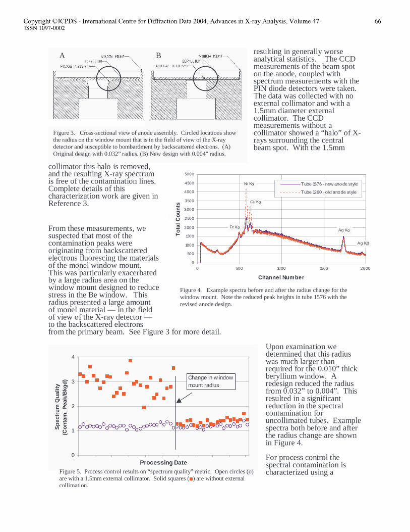
resulting in generally worse analytical statistics. The CCD measurements of the beam spot on the anode, coupled with spectrum measurements with the PIN diode detectors were taken. The data was collected with no external collimator and with a 1.5mm diameter external collimator. The CCD measurements without a collimator showed a “halo” of X-rays surrounding the central beam spot. With the 1.5mm
collimator this halo is removed, and the resulting X-ray spectrum is free of the contamination lines. Complete details of this characterization work are given in Reference 3.
From these measurements, we suspected that most of the contamination peaks were originating from backscattered electrons fluorescing the materials of the monel window mount. This was particularly exacerbated by a large radius area on the window mount designed to reduce stress in the Be window. This radius presented a large amount of monel material — in the field of view of the X-ray detector — to the backscattered electrons from the primary beam. See Figure 3 for more detail.
Upon examination we determined that this radius was much larger than required for the 0.010” thick beryllium window. A redesign reduced the radius from 0.032” to 0.004”. This resulted in a significant reduction in the spectral contamination for uncollimated tubes. Example spectra both before and after the radius change are shown in Figure 4. For process control the spectral contamination is characterized using a
B
0
500
1000
1500
2000
2500
3000
3500
4000
4500
5000
0 500 1000 1500 2000
Channel Number
To
tal C
ou
nts
Tube 1576 - new anode style
Tube 1260 - o ld anode style
Fe Kα
Ag Kβ
Ag Kα
Cu Kα
Ni Kα
Figure 4. Example spectra before and after the radius change for the window mount. Note the reduced peak heights in tube 1576 with the revised anode design.
0
1
2
3
4
Processing Date
Sp
ectr
um
Qu
alit
y (C
on
tam
. Pea
k/B
kgd
) Change in w indow mount radius
Figure 5. Process control results on “spectrum quality” metric. Open circles (o) are with a 1.5mm external collimator. Solid squares (■) are without external collimation.
Figure 3. Cross-sectional view of anode assembly. Circled locations show the radius on the window mount that is in the field of view of the X-ray detector and susceptible to bombardment by backscattered electrons. (A) Original design with 0.032” radius. (B) New design with 0.004” radius.
A B
Copyright ©JCPDS - International Centre for Diffraction Data 2004, Advances in X-ray Analysis, Volume 47. 66 ISSN 1097-0002

“spectrum quality” metric, which is the peak height of the contamination peak divided by the height of the continuum background under the peak [3]. Figure 5 shows the process control results for the time period before and after the change on the radius of the window mount. The reduction in spectral contamination is obvious. TARGETED CATHODE IMPROVEMENT The beam spot size, location, and stability on the anode are largely a function of the filament location and the focusing optics at the cathode end of the tube. In an effort to improve spot stability and reduce the spot size for imaging applications we have undertaken an aggressive redesign of the cathode optics. The design was accomplished using Opera electron beam modeling software [4]. The goal was to implement an optimized version of an industry-standard T-slot cathode optic, which required a full 3-dimensional model because of the cylindrical filament. The following approach was used in the design engineering, with some results shown in Figure 6:
• First, a 2D electrostatic model was generated. Axi-symmetric and XY-symmetric models were generated. Geometrical numerical analysis was necessary in order to optimize the cathode geometry. The geometry permits control of the focusing of electrons emitted from the front and back surfaces of the filament.
• Next, a 2D space charge model was generated. This built upon the 2D electrostatic
model to include the effects of space charge. This includes electron beam trajectories computed with the influence of space charge on beam emission and transport. Indications are that a small beam spot is achievable, with the recommendation to proceed with 3D modeling.
• Then, a 3D preliminary statics model was generated. This included electric
equipotentials and fields for the 3D model with a flat filament.
Figure 6. Electron beam model of improved cathode. (A) Finished cathode optic model showing electron trajectories. (Trajectories do not indicate current density.) (B) Beam spot profile on the anode in the direction of width of the filament. (C) Beam spot profile in the filament length direction. For reference, graph dimension units are in inches.
40µm FWHM
60µm FWHM
A
B
C
Copyright ©JCPDS - International Centre for Diffraction Data 2004, Advances in X-ray Analysis, Volume 47. 67 ISSN 1097-0002
• Finally, a 3D space charge model was completed, including electron beam trajectories computed with the influence of space charge on beam emission and transport. The flat filament design was replaced with a cylindrical filament model. Preliminary tube behavior was shown with plots of the electric equipotentials, electric fields, beam trajectories, and the focal spot on the anode surface. Predicted beam focal spot size is shown in Figure 6 along with the model rendering of the filament positioned in the T-slot and some representative electron trajectories.
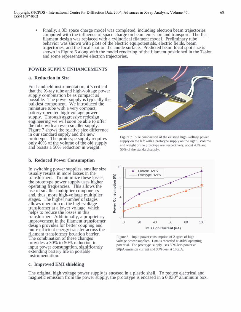
POWER SUPPLY ENHANCEMENTS a. Reduction in Size For handheld instrumentation, it’s critical that the X-ray tube and high-voltage power supply combination be as compact as possible. The power supply is typically the bulkiest component. We introduced the miniature tube with a very compact, battery-operated high-voltage power supply. Through aggressive redesign engineering we will soon be able to offer the tube with an even smaller supply. Figure 7 shows the relative size difference in our standard supply and the new prototype. The prototype supply requires only 40% of the volume of the old supply and boasts a 50% reduction in weight. b. Reduced Power Consumption In switching power supplies, smaller size usually results in more losses in the transformers. To minimize these losses, the prototype power supply uses higher operating frequencies. This allows the use of smaller multiplier components and, thus, more high-voltage multiplier stages. The higher number of stages allows operation of the high-voltage transformer at a lower voltage, which helps to reduce the losses in this transformer. Additionally, a proprietary improvement in the filament transformer design provides for better coupling and more efficient energy transfer across the filament transformer isolation barrier. The combination of these changes provides a 30% to 50% reduction in input power consumption, significantly extending battery life in portable instrumentation. c. Improved EMI shielding The original high voltage power supply is encased in a plastic shell. To reduce electrical and magnetic emission from the power supply, the prototype is encased in a 0.030” aluminum box.
0
2
4
6
8
10
0 20 40 60 80 100
Emission Current (uA)
Po
wer
Co
nsu
mp
tio
n (
W)
Current HVPSPrototype HVPS
Figure 8. Input power consumption of 2 types of high-voltage power supplies. Data is recorded at 40kV operating potential. The prototype supply uses 50% less power at 20µA emission current and 30% less at 100µA.
Figure 7. Size comparison of the existing high -voltage power supply on the left with a prototype supply on the right. Volume and weight of the prototype are, respectively, about 40% and 50% of the standard supply.
Copyright ©JCPDS - International Centre for Diffraction Data 2004, Advances in X-ray Analysis, Volume 47. 68 ISSN 1097-0002
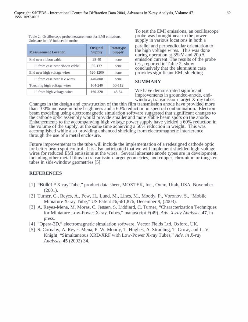
To test the EMI emissions, an oscilloscope probe was brought near to the power supply in various locations in both a parallel and perpendicular orientation to the high voltage wires. This was done during operation at 35kV and 20µA emission current. The results of the probe test, reported in Table 2, show conclusively that the aluminum case provides significant EMI shielding. SUMMARY We have demonstrated significant improvements in grounded-anode, end-window, transmission-target X-ray tubes.
Changes in the design and construction of the thin film transmission anode have provided more than 100% increase in tube brightness and a 60% reduction in spectral contamination. Electron beam modeling using electromagnetic simulation software suggested that significant changes to the cathode optic assembly would provide smaller and more stable beam spots on the anode. Enhancements to the accompanying high voltage power supply have yielded a 60% reduction in the volume of the supply, at the same time achieving a 50% reduction in weight. This was accomplished while also providing enhanced shielding from electromagnetic interference through the use of a metal enclosure. Future improvements to the tube will include the implementation of a redesigned cathode optic for better beam spot control. It is also anticipated that we will implement shielded high-voltage wires for reduced EMI emissions at the wires. Several alternate anode types are in development, including other metal films in transmission-target geometries, and copper, chromium or tungsten tubes in side-window geometries [5]. REFERENCES [1] “Bullet X-ray Tube,” product data sheet, MOXTEK, Inc., Orem, Utah, USA, November
(2001). [2] Turner, C., Reyes, A., Pew, H., Lund, M., Lines, M., Moody, P., Voronov, S., “Mobile
Miniature X-ray Tube,” US Patent #6,661,876, December 9, (2003). [3] A. Reyes-Mena, M. Moras, C. Jensen, S. Liddiard, C. Turner, “Characterization Techniques
for Miniature Low-Power X-ray Tubes,” manuscript F(49), Adv. X-ray Analysis, 47, in press.
[4] “Opera-3D,” electromagnetic simulation software, Vector Fields Ltd, Oxford, UK. [5] S. Cornaby, A. Reyes-Mena, P. W. Moody, T. Hughes, A. Stradling, T. Grow, and L. V.
Knight, “Simultaneous XRD/XRF with Low-Power X-ray Tubes,” Adv. in X-ray Analysis, 45 (2002) 34.
Measurement Location
Original Supply
Prototype Supply
End near ribbon cable 28-40 none
1” from case near ribbon cable 60-132 none
End near high voltage wires 520-1200 none
1” from case near HV wires 440-800 none
Touching high voltage wires 104-240 56-112
1” from high voltage wires 160-320 48-64
Table 2. Oscilloscope probe measurements for EMI emissions. Units are in mV induced in probe.
Copyright ©JCPDS - International Centre for Diffraction Data 2004, Advances in X-ray Analysis, Volume 47. 69 ISSN 1097-0002