The Theoretical Framework of the Modified Organic Rankine ...
Abstract for the 29th Intl Workshop on Water Waves and Floating Bodies, Osaka (Japan), March 30 - April 02, 2014
Improvement of Rankine Panel Method by Theoretical Considerationof Panel Forces on Ship Hull
by Kenji SASA∗ and Masashi KASHIWAGI
Dept. of Maritime Science, Kobe University, Kobe, JapanE-mail: [email protected]
Highlights• New considerations are implemented for the suitable model as the higher order evaluation in the integration
equation of Rankine Panel Method, which is expected to apply for the highly accurate practical model.
• Higher Order Sources and Normal Dipoles Method is the best model for advantages in the numerical procedureat singular panels and is little influeces by the second order derivations on the free water surface condition.
1. IntroductionNowadays, our daily life cannot be sustained without global ship transportation, which carries more than 95 percentsof these cargoes, thus a cost effective and safety transportation are strictly required. Weather routing is the one of themost important themes. When we consider the international voyage across the ocean, the possibility of encounteringstormy weathers cannot be ruled out. The evaluation of ship performance in heavy seas must be more accuratethan ever. Although there are many studies on seekeeping theories, they have not practically used. The complexityof theories may influences to the situation. RIOS(The Research Initiative on Oceangoing Ships)[1] has constructedon the theory of EUT(Enhanced Unified Theory)[2] recently, it seems the first step as the high accuracy practicalmodel. Kashiwagi et al. also tried a theoretical improvement of the EUT for high speed vessels. However, effectiveimprovement cannot be achieved yet[2]. Three dimensional methods are theoretically prior than two dimensionalmethods, however, source points must be evaluated as panels, not lines. It means that numerical influences aremore sensitive where the shape is complex, such as in bow and aft parts of vessels. Constant Panel Method (CPM)is commonly used to solve the integral equation now, matrix elements is represented as uniform values on a panel.There are also some studies on the higher order evaluation of panel integration in frequency analysis without forwardspeed, or time domain analysis with forward speed. However, there are very few on frequency analysis with forwardspeed. Rankine Panel Method (RPM) is expected to apply as the new practical method, however, current versionis modeled by CPM. There are some possibilities to improve the accuracy by introducing higher order evaluationmodels. Here, theoretical background is summarized and considered the suitable theoretical method to RPM.
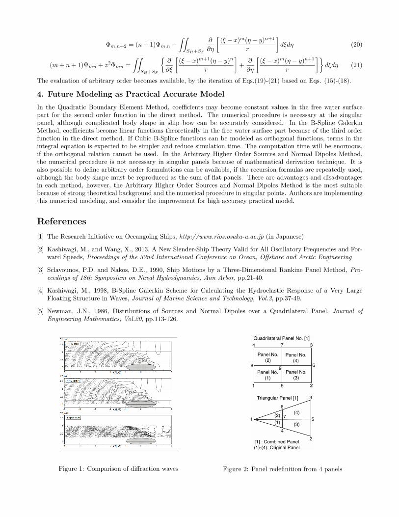
2. Characteristics of Contant Panel Method in Rankine Panel MethodRPM is the three dimensional theory, its kernel function as the fundamental solution term of 1/r. r is the distancebetween the field point P (x, y, z) and the panel point Q(ξ, η, ζ) as r =
√(ξ − x)2 + (η − y)2 + (ζ − z)2. It means
that the kernel function does not contain free-surface Green function term, which is related on free water surfaceand far field radiation conditions. Formulations in free water surface become necessary, in addition to that inbody surface. The Green function method, which is strictly theoretical model, is also rather difficult to considerthe double body flow into the free-surface term. RPM can consider it by applying directly free water surfacecondition into the integration equation, thus it is expected to be the practical model. It is also necessary toconsider the integration terms in far field areas in a strictly theoretical meanings, however, it is impossible to definethem in numerical modeling. The panel shift technique, which is the one column shift of panels on free watersurface, is often used to satisfy this condition. Numerical techniques are sometimes required for the complicity ofradiation and diffraction waves, especially vessels with forward speed. Figure 1 shows the comparison of diffractionwaves (cos component) around the modified wigley model ship, between model test and numerical simulation.Simulated waves underestimate observed values, especially near the ship bow. This point strongly relates to theunderestimation of the added resistance. It is thought to be insufficient for the evaluation of panel integrationshere. CPM cannot consider the continuity of values for neighboring panels, especially in remarkable shape variationparts. The integration equation in case of a direct method is expressed as follows.
2πϕ(P ) −∫∫
SH +SF
ϕ(Q) ∂
∂nQ
(1r
)dS(Q) = −
∫∫SH +SF
∂ϕ(Q)∂nQ
(1r
)dS(Q) (1)
where, ϕ shows the unknown velocity potential, nQ is the normal vector on the panel Q, dS(Q) shows the area ofthe panel Q, SH and SF show body surface and free water surface, respectively. In RPM with indirect method, thevelocity potential is expressed by source and kernel function, as follows.
ϕ(P ) =∫∫
SH +SF
σ(Q)G(P, Q)dS (2)
where, σ(Q) shows source function as unknown parameter, and G(P, Q) shows the kernel function. RPM considersthe double body flow on SH , the kernel function considers mirror panels against the water surface. Eq.(2) can betransformed as follows.
ϕj(P ) = −∫∫
SH
σj(Q) {G1(P, Q) + G2(P, Q)} dS −∫∫
SF
σj(Q)G1(P, Q)dS (3)
where, G1(P, Q) and G2(P, Q) are kernel functions on ship hull and on mirror image of them as follows.
G1(P, Q) = 14πr
, G2(P, Q) = 14πr′ (4)
r′ =√
(ξ − x)2 + (η − y)2 + (ζ + z)2 (5)
Here, the free surface condition considering the double body flow, by Sclavounos and Nakos[3], is used as follows.
−Keϕj(P ) + 2iτ∇ΦD(P ) · ∇ϕj(P ) + 1K0
∇ΦD(P ) · ∇(∇ΦD(P ) · ∇ϕj(P )
)+ 1
2K0∇
(∇ΦD(P ) · ∇ΦD(P )
)· ∇ϕj(P ) + ∂ϕj(P )
∂z= 0 on z = 0 (6)
where, Ke shows the wave number expressed by the encounter frequency, ωe and Ke = ωe/g2, K0 shows incidentwave number , ΦD(P ) shows steady velocity potential in double body flow at P , ∇ means the partial differentiationwith x and y. The body surface condition is also defined for radiation problem (suffix j = 1 − 6) and diffractionproblem (suffix j = 7).
∂ϕj(P )∂n
= nj + U
iωemj (j = 1 ∼ 6), ∂ϕ7(P )
∂n= −∂ϕ0(P )
∂non SH (7)
where, mj shows influence term in steady flow for j mode motion, nj shows normal vector component for j modemotion, ϕ0 shows the velocity potential of incident wave (ϕ0 = iek0z−ik0(x cos χ+y sin χ)). Integral equations canbe obtained, if Eq.(2) is substituted to Eqs.(6)-(7). It is obvious that there are some terms of the second orderdifferential. If the direct method as Eq.(1) is used here, coefficients become zero or constant values theoreticallybecause the velocity potential is expressed as the first order or the second order functions. Based on this point,advantages and disadvantages of following methods will be considered here.
3. Higher Order Panel EvaluationWhen the integration equation (1) is discretized into N panels, it is expressed as follows.
2πϕ(Pi) −N∑
j=1ϕ(Qj)Dij = −
N∑j=1
(∂ϕ
∂n
)j
Sij (i = 1 − N) (8)
Dij and Sij are expressed in CPM as follows.
Dij =∫∫
Sj
∂
∂n
(1r
)dS(Q), Sij =
∫∫Sj
1r
dS(Q) (9)
where, Sj shows the discretized j-th panel. There are some methods to evaluate as the higher order model, thepossibility of following three models is considered for the application to RPM.3.1 Quadratic Boundary Element MethodIf the body shape of floating structures are difficult to express as the sum of flat panels, nonlinear mode functions
are often used. Velocity potentials are also expressed as the multiply of nonlinear mode function and potential inpanel node as follows.
ϕj(x, y, z) =m∑
k=1
Nk(ξ, η)ϕjk(xk, yk, zk) (10)
where, (x, y, z) show coordinate of arbitrary point in the panel, (xk, yk, zk) show coordinate of panel node, (ξ, η)show coordinate normalized panel node at the water surface, m is the number of node, and Nk(ξ, η) shows modefunctions of the second order. Mode functions are expressed as the second order polynomials for 7 and 9 nodes oftriangular and quadrilateral panels. Figure 2 shows the relation of node number and defined panels. As shown here,an element in the integration equation consists of 4 neighboring panels. It shows that the redefinition of panelsand nodes becomes necessary, so N in Eq.(8) means the number of redefined panels. If Eq.(10) is substituted intoEq.(8), the integration equation as the second order expression can be modeled.3.2 Cubic B-Spline Galerkin MethodUnknown velocity potential is modeled as the combination of the cubic B-Spline functions[4], shown as follows.
ϕ(x, y, z) =N+3∑j=1
αjBj(P, Q) (11)
where, Bj(P, Q) is the third order B-Spline function with parameters of P and Q. They are obtained by Boor-Cox’s recurrence formula using coordinates include 4 neighboring panel nodes. If B-Spline functions, Bk(P, Q)are multiplied to the integration equations and integrate them for the body surface, simultaneous equations forunknown coefficients, αj , can be derived as follows.
N+3∑j=1
αj
{2π
∫∫SH +SF
Bk(P, Q)Bj(P, Q)dS −∫∫
SH +SF
Bk(P, Q)∫∫
SH +SF
Bj(P, Q)DijdSdS
}= −Rj (12)
where, the right hand term, Rj shows as follows.
Rj =∫∫
SH +SF
Bk(P, Q)N+3∑j=1
(∂ϕ
∂n
)j
SijdS (13)
3.3 Arbitrary Higher Order Sources and Normal Dipoles MethodNewman derived the evaluation of the integral equation with linear and nonlinear kernel functions[5]. They aredefined as the zero order elements, Ψ00 and Φ00, corresponding to D and S in Eq.(8).
Ψ00 =∫∫
SH +SF
1r
dξdη, Φ00 =∫∫
SH +SF
[∂
∂ζ
(1r
)]z=0
= z
∫∫SH +SF
1r3 dξdη (14)
These integrations are theoretically modeled for numerical analysis, without special procedures in singular panels.Details are not described here, see the reference[5]. Then, linear and bilinear components are derived as follows.(
Ψ10Ψ01
)=
∫∫SH +SF
(ξη
)1r
dξdη =(
xy
)Ψ00 ∓
4∑n=1
(cos θn
sin θn
) ∫Sn
rdℓ (15)
(Φ10Φ01
)= z
∫∫SH +SF
(ξη
)1r3 dξdη =
(xy
)Φ00 ± z
4∑n=1
(sin θn
cos θn
) ∫Sn
1r
dℓ (16)
Ψ11 =∫∫
SH +SF
ξη
rdξdη =
4∑n=1
cos θn
∫ Sn
0r (ξn − x + s cos θn) ds + xΨ01 + yΨ10 − xyΨ00 (17)
Φ11 = z
∫∫SH +SF
ξη
r3 dξdη = z4∑
n=1cos θn
∫ Sn
0
ξn − x + s cos θn
rds + xΦ01 + yΦ10 − xyΦ00 (18)
where, θn shows the n-th angle between the horizontal axis and the panel node, s shows distance between panelnodes, (x, y, z) is the field point, and (ξ, η) is the panel node. Values in higher orders can be obtained by followingrecurrence formulas.
Φm+2,n = (m + 1)Ψm,n −∫∫
SH +SF
∂
∂ξ
[(ξ − x)m+1(η − y)n
r
]dξdη (19)
Φm,n+2 = (n + 1)Ψm,n −∫∫
SH +SF
∂
∂η
[(ξ − x)m(η − y)n+1
r
]dξdη (20)
(m + n + 1)Ψmn + z2Φmn =∫∫
SH +SF
{∂
∂ξ
[(ξ − x)m+1(η − y)n
r
]+ ∂
∂η
[(ξ − x)m(η − y)n+1
r
]}dξdη (21)
The evaluation of arbitrary order becomes available, by the iteration of Eqs.(19)-(21) based on Eqs. (15)-(18).
4. Future Modeling as Practical Accurate ModelIn the Quadratic Boundary Element Method, coefficients may become constant values in the free water surfacepart for the second order function in the direct method. The numerical procedure is necessary at the singularpanel, although complicated body shape in ship bow can be accurately considered. In the B-Spline GalerkinMethod, coefficients become linear functions theoretically in the free water surface part because of the third orderfunction in the direct method. If Cubic B-Spline functions can be modeled as orthogonal functions, terms in theintegral equation is expected to be simpler and reduce simulation time. The computation time will be enormous,if the orthogonal relation cannot be used. In the Arbitrary Higher Order Sources and Normal Dipoles Method,the numerical procedure is not necessary in singular panels because of mathematical derivation technique. It isalso possible to define arbitrary order formulations can be available, if the recursion formulas are repeatedly used,although the body shape must be reproduced as the sum of flat panels. There are advantages and disadvantagesin each method, however, the Arbitrary Higher Order Sources and Normal Dipoles Method is the most suitablebecause of strong theoretical background and the numerical procedure in singular points. Authors are implementingthis numerical modeling, and consider the improvement for high accuracy practical model.
References[1] The Research Initiative on Oceangoing Ships, http://www.rios.osaka-u.ac.jp (in Japanese)
[2] Kashiwagi, M., and Wang, X., 2013, A New Slender-Ship Theory Valid for All Oscillatory Frequencies and For-ward Speeds, Proceedings of the 32nd International Conference on Ocean, Offshore and Arctic Engineering
[3] Sclavounos, P.D. and Nakos, D.E., 1990, Ship Motions by a Three-Dimensional Rankine Panel Method, Pro-ceedings of 18th Symposium on Naval Hydrodynamics, Ann Arbor, pp.21-40.
[4] Kashiwagi, M., 1998, B-Spline Galerkin Scheme for Calculating the Hydroelastic Response of a Very LargeFloating Structure in Waves, Journal of Marine Science and Technology, Vol.3, pp.37-49.
[5] Newman, J.N., 1986, Distributions of Sources and Normal Dipoles over a Quadrilateral Panel, Journal ofEngineering Mathematics, Vol.20, pp.113-126.
Figure 1: Comparison of diffraction waves
1 2
34
5
6
7
89
1
2
3
4
5
6
7
Quadrilateral Panel No. [1]
Triangular Panel [1]
Panel No.
(1)
Panel No.
(2)
Panel No.
(3)
Panel No.
(4)
(1) (3)
(4)(2)
[1] : Combined Panel
(1)-(4): Original Panel
Figure 2: Panel redefinition from 4 panels