IMPROVEMENT OF FRONT CAR BUMPER SYSTEM MUHAMAD …
24
IMPROVEMENT OF FRONT CAR BUMPER SYSTEM MUHAMAD FIRDAUS BIN MAHMUD Report submitted in partial fulfillment of the requirements for the award of the degree of Bachelor of Mechanical Engineering with Automotive Faculty of Mechanical Engineering UNIVERSITI MALAYSIA PAHANG JUNE 2008
Transcript of IMPROVEMENT OF FRONT CAR BUMPER SYSTEM MUHAMAD …

IMPROVEMENT OF FRONT CAR BUMPER SYSTEM
MUHAMAD FIRDAUS BIN MAHMUD
Report submitted in partial fulfillment of the requirements for the award of the degree of
Bachelor of Mechanical Engineering with Automotive
Faculty of Mechanical Engineering UNIVERSITI MALAYSIA PAHANG
JUNE 2008

ii
SUPERVISOR’S DECLARATION
We hereby declare that we have checked this project and in our opinion this project is
satisfactory in terms of scope and quality for the award of the degree of Bachelor of
Mechanical Engineering with Automotive/Manufacturing*
Signature
Name of Supervisor: ZAMRI MOHAMED
Position: Lecturer
Date: 10 November 2008
Signature
Name of Panel: AZIZUDDIN BIN ABD AZIZ
Position: Lecturer
Date: 10 November 2008
* Delete any

iii
DECLARATION
I hereby declare that the work in this report is my own except for quotations and
summaries which have been duly acknowledged. The report has not been accepted for
any degree and is not concurrently submitted for award of other degree.
Signature
Name: MUHAMAD FIRDAUS BIN MAHMUD
ID Number: MH05049
Date: 10 November 2008

iv
ACKNOWLEGDEMENT
Firstly I would like to express my deep gratitude to my supervisor, Mr Zamri Bin
Mohamed for his precious guidance, admonition and incessant encouragement to me in
the way to completing this project. I appreciate and utilize all his advice and supervision
that contribute to finishing this project.
I would also like to wish my special thanks to beloved Faculty of Mechanical
Engineering for giving me permission to borrow and use the Proton Pesona in the
Mechanical Laboratory as my guidance model in designing the front car bumper.
Last but not least, my sincere gratitude to my entire friend in my section group of
M13 and M12 that always give me a support and help to overcome my problem and
difficulties contribute to completing this project.

v
ABSTRACT
Designing the bumper with the focus on an improvement aspect is very
important in the automotive industry. The goals are to increase the performance of the
bumper and also to find the solution to reduce the cost of the bumper hence able to
reduce the production cost. The costs of the bumper is high because of the amount of
material used and it also involves many processes including making the grille at the
center of bumper. The new design considers on reducing the amount of material use and
also eliminating the process involve in manufacture the bumper for example eliminating
the grille attachment. The new design also must improve the ability to absorb more
impact load and increase the protection of the front car component. This project
intention is to design an improved of front car bumper and to find the solution for the
problem of high cost and the replacing cost for the front bumper and lastly emphasizing
the cost reducing aspect. The method have been employed was study the front bumper
system, design and analyze the alternative front bumper using CAD software. The
suitable material that can be used as the bumper in terms of economical but still
maintaining the toughness is Plastic-Polycarbonate (Molded) which is not expensive
compare to the best material from the analysis E-Glass Fiber, Plastic-Nylon Type 6/6
and Plastic ABS (Molded). The suitable material to be use for making beam is AISI E
52100 Steel. Rearrangement of the mounting positions gives a different effect on the
ability to withstand the impact force. Additional plate in the improvement design proved
increasing the toughness of the beam.

vi
ABSTRAK
Merekabentuk bumper dengan member focus kepada aspek pembaikan adalah
sangat penting didalam industri automotif dalam usaha untuk meningkatkan prestasi
bumper dan juga untuk mencari penyelesaian untuk mengurangkan kos bumper dengan
itu mampu mengurangkan kos produksi. Kos bumper adalah tinggi kerana jumlah bahan
yang digunakan dan juga bilangan proses yang terlibat adalah banyak termasuk proses
membuat grille pada bahagian tengah bumper. Rekabentuk baru mempertimbangkan
tentang pengurangan bahan yang digunakan dan juga mengurangkan proses yang terlibat
dalam menghasilkan bumper sebagai contoh menghapuskan proses pemasangan grille.
Namun rekabentuk bumper yang baru juga perlu bertambah baik dalam keupayaan untuk
menyerap lebih banyak daya hentaman, meningkatkan pertahanan komponen hadapan
kereta. Tujuan projek ini adalah untuk merekabentuk bumper kereta yang
dipertingkatkan kualitinya dan untuk mencari penyelesaian bagi masalah harga bumper
dan harga menukarganti bumper yang mahal dan akhir sekali menekankan aspek
pengurangan kos. Kaedah yang digunakan ialah melakukan pengkajian terhadap system
bumper kereta, merekabentuk dan menganalisis rekabentuk bumper alternatif dengan
menggunakan perisian CAD. Bahan yang sesuai untuk digunakan dalam pembuatan
bumper dari aspek ekonomikal tetapi tetap mengekalkan kekuatannya ialah Plastic-
Polycarbonate (Molded) yang kurang mahal dibandingkan dengan material terbaik
daripada analisis E-Glass Fiber, Plastic-Nylon Type 6/6 and Plastic ABS (Molded).
Bahan yang sesuai untuk dibuat ‘beam’ ialah AISI E 52100 Steel. Penyusunan semula
posisi pemasangan member kesan yang berbeza pada keupayaan bumper untuk
menampung daya impak. Penambahan plat didalam rekabentuk yang diperbaharui
terbukti meningkatkan kekuatan pada ‘beam’.

vii
TABLE OF CONTENTS
Page
TITLE PAGE i
SUPERVISOR DECLARATION ii
DECLARATION iii
ACKNOWLEDGEMENT iv
ABSTRACT v
ABSTRAK vi
TABLE OF CONTENTS vii
LIST OF TABLES x
LIST OF FIGURES xi
LIST OF GRAPH xiii
LIST OF SYMBOLS xiv
LIST OF ABBREVIATIONS XV
LIST OF APPENDICES xvi
CHAPTER 1 INTRODUCTION 1
1.1 Introduction 1
1.2 Problem Statement 2
1.3 Objectives 2
1.4 Limitation 4
CHAPTER 2 LITERATURE REVIEW 5
2.1 Introduction 5
2.2 Front Bumper System 5

viii
2.3 Bumper Hydraulic Absorbing System 8
2.4 Underride and Override 9
2.5 Bumper Material Selection 10
2.6 Importance of Bumper 11
2.7 Attribute of a Good Bumper System 11
2.8 Bumper Do Not Bump 12
2.9 Bumper Beam 12
2.10 Impact Time 14
CHAPTER 3 METHODOLOGY 16
3.1 Introduction 16
3.1.1 Literature review 16 3.1.2 Benchmarking Activity 16
3.2 Designing Process 18
3.3 Improvement on Fascia Bumper 21
3.4 Improvement on Beam 22
3.5 Analysis the Design in ALGOR 23
3.6 Flow Chart for Project Methodology 25
CHAPTER 4 RESULTS AND DISCUSSION 27
4.1 Introduction 27
4.2 Impact Force Equation 28
4.3 Bill Of Material 30
4.4 Analysis 30
4.5 Result Analysis for Fascia 32
4.6 Result Analysis for Beam 38
CHAPTER 5 CONCLUSION AND RECOMMENDATION 43

ix
5.1 Conclusion 43
5.2 Further Study Recommendation 44
REFERENCES 45
APPENDICES A – B4 46-50

x
LIST OF TABLES
Figure No. Page 3.1 Bumper and beam dimension 17 4.1 Bill of Material 30 4.2 Bumper Analysis Result 32 4.3 Attachment Analysis Result 35 4.4 Beam Analysis Result 39 4.5 Beam design analysis result 41

xi
LIST OF FIGURES
Figure No. Page 2.1 General component and arrangement of front bumper system 6 2.2 Attachments of foam material 7 2.3 An illustration of bracket attachment 8 2.4 The schematic diagram of hydraulic bumper system 9 2.5 Example of under ride crash damage 10 2.6 A bumper reinforcement bar, shown without the plastic bumper cover 11 2.7 The example bumper beam structure 13 3.1 Front view of Proton Pesona front bumper 17 3.2 Initial design of front bumper 19 3.3 Creating the headlight space 19 3.4 Final design with grille space 19 3.5 Top, front, side and isometric view 20 3.6 Original beam design 20 3.7 Beam design with additional plate 21 3.8 The ordinary and the improved bumper design 22 3.9 The ordinary and the improved beam design 22 3.10 Bumper boundary condition in ALGOR 24 3.11 Beam boundary condition in ALGOR 24 4.1 Load applied in ALGOR analysis for fascia and beam 31 4.2 Displacement magnitude of E-Glass Fiber 33

xii
4.3 Stress Concentration of E-Glass Fiber 34 4.4 Displacement magnitude of Plastic-LDPE 34 4.5 Stress Concentration of Plastic-LDPE 35 4.6 Manipulation of attachment position (screw mounting) 36 4.7 The toughness mounting position 37 4.8 The best mounting position in terms of reducing screw 38 4.9 Beam Design A (original design) 38 4.10 Displacement magnitude of steel 40 4.11 Displacement magnitude of Aluminium 40 4.12 Design A 41 4.13 Design B 41 4.14 Comparison in displacement magnitude 41 4.15 Comparison in stress concentration 42

xiii
LIST OF GRAPH
Graph No. Page 2.1 Barrier Impact Test Result 15 4.1 Impact Time 29

xiv
LIST OF SYMBOLS
∑ Summation ∫ Integration ∆t Time interval

xv
LIST OF ABBREVIATIONS
CD Coefficient of Drag FEA Finite Element Analysis GM Glass Mat Thermoplastic 2D Two Dimensions 3D Three Dimensions CAE Computational Aided Engineering ABS Acrylonitrile Butadiene Styrene HDPE High Density Polyethylene LDPE Low Density Polyethylene FEP Fluorinated Ethylene Propylene
AISI American Iron and Steel Institute
LIST OF APPENDIX

xvi
APPENDIX TITLE PAGE Appendix A Gantt Chart 46
Appendix B1 Bumper Design 47
Appendix B2 Bumper Design 48
Appendix B3 Beam Design A 49
Appendix B4 Beam Design B 50

CHAPTER 1
INTRODUCTION
1.1 Introduction
Bumper has been an important feature in protecting the vehicle from serious
damage to the car component in a low speed collision. Especially when the collision
causing damage to the expensive-to-repair part like fender, hood and intercooler.
Bumper is also involves in improving the performance of the car. Bumper size and the
aerodynamic feature of the bumper are the important aspects in lowering the coefficient
of drag, CD. The efficient bumper design will also increase the down force of the car
when it accelerates to give more grips to the tire and the road. This will give a good
handling to the driver ever in high speed driving.
The car bumper is designed to prevent or reduce physical damage to the front
and rear ends of passenger motor vehicles in low-speed collisions. Automobile bumpers
are not typically designed to be structural components that would significantly
contribute to vehicle crashworthiness or occupant protection during front or rear
collisions. It is not a safety feature intended to prevent or mitigate injury severity to occupants
in the passenger cars. Bumpers are designed to protect the hood, trunk, grille, fuel, exhaust
and cooling system as well as safety related equipment such as parking lights,
headlamps and taillights in low speed collisions.

2
Bumpers beam are made of heavy sheet metal and are mounted on the front and
rear of the car. Bumpers are bent and formed into specific shapes in order to absorb and
deliver momentum during a collision. In the event of a collision, the bumper absorbs
some of the impact, which decreases damage to the car and its occupants. It also protects
the front of the car by diverting all of the car's momentum to the object with which it has
collided. The bumper beam is mounted to the car's chassis with special impact absorbers.
These shock absorbers are often spring loaded. In slow speed collisions, this allows the
bumper to compress, and then extend back to its original position. All bumpers are
designed to absorb the energy of the impact. They do this through a series of valves and
air chambers. Some car bumpers have hydraulic chambers. In the event of a collision,
the absorption unit allows air and/or hydraulic fluid to pass through small openings.
Forcing the air/fluid through the valve openings absorbs the energy from the collision.
The bumper's job is to minimize damage, primarily to the occupants of the vehicle and
to the vehicle itself.
1.2 Problem Statement
Nowadays the part cost for front bumper is still high and the cost for replacing is
quite expensive especially if surrounding area or part also damaged. Many part that
make up a bumper system, involving a lot of material and processes there for the
manufacturer difficult to reduce the price. Customer also blame to the manufacture that
the bumper easily to damage although the collision was slow. The material of the
bumper should be analyzed to find the alternative material that can improve the
toughness.
1.3 Objective
The main objectives of this project is first to study the front bumper properties
and the sample of the car was the Proton Pesona. The bumper design of the Proton
Pesona has been benchmarked to determine the real dimension of the bumper. Second
objective is to design the generic front bumper using Solidwork software including the

3
improvement that suitable to be made increase the performance of the bumper. The
designs then were analyzed using Finite Element Analysis method (FEA) to study the
toughness of the bumper design by performing the impact test. The aim of this process is
to determine the strength of the front bumper, identify the segment or part that the crack
will occur or where the concentration of stress is high when force is attached in front of
the bumper. This is to ensure that the designed bumper is functioning properly in absorb
the impact energy and protecting the front car component. The third objective is to
emphasize the improvement and cost reduction aspect of the designed bumper including
the beam design.
This project will focus on designing a improvement front bumper that meets all
the regulation aspect. In this research the consideration of improving the front car
bumper will be the most important things. To achieve the objective of the project, the
following research activities are performed:
1. Literature review, collecting and gathering the information about front bumper.
2. Benchmark the current front car bumper design (Proton Pesona)
3. Make a comparison between the current design and the alternative design.
4. Perform CAE simulation to the alternative bumper.
In the end of this project, the expected outcome is all the problem stated above
can be solve, the part cost of the front bumper and the cost for repairing can be reduce.
Reducing the parts that make up the bumper system, there for reducing the price is
possible. The suitable material for the fascia and the beam will be determined so that the
improvement designs have the toughness and increase in ability to withstand the impact
force. The alternative design predicated to give a good protection to the front car
component when low speed collision happened and work properly in absorb the energy
of the impact. Also it should be easy to assemble and attached (installation).

4
1.4 Limitations
The limitation for this project is hard to find the journal and book about design
the low cost front bumper in the Knowledge Management Centre (KMC) of University
Malaysia Pahang. The whole literature review journals are searched in internet.

CHAPTER 2
LITERATURE REVIEW
2.1 Introduction
This chapter will provide detail description of literature review done according to
the project title of front car bumper system. A bumper is a car shield made of steel,
aluminium, rubber, or plastic that is mounted on the front and rear of a passenger car.
When a low speed collision occurs, the bumper system absorbs the shock to prevent or
reduce damage to the car. Some bumpers use energy absorbers or brackets and others are
made with a foam cushioning material. The car bumper is designed to prevent or reduce
physical damage to the front and rear ends of passenger motor vehicles in low-speed
collisions. Automobile bumpers are not typically designed to be structural components
that would significantly contribute to vehicle crashworthiness or occupant protection
during front or rear collisions. It is not a safety feature intended to prevent or mitigate
injury severity to occupants in the passenger cars. Bumpers are designed to protect the
hood, trunk, grille, fuel, exhaust and cooling system as well as safety related equipment
such as parking lights, headlamps and taillights in low speed collisions (Status Report,
Vol 4, No 2, IIHS, 2007).
2.2 Front Bumper System
Generally, a bumper is attached to either end of a vehicle to absorb impact in a
collision, thereby protecting passenger. As shown in figure 1, a conventional bumper
system comprises a bumper cover 1 defining an outer appearance of the bumper system,
6
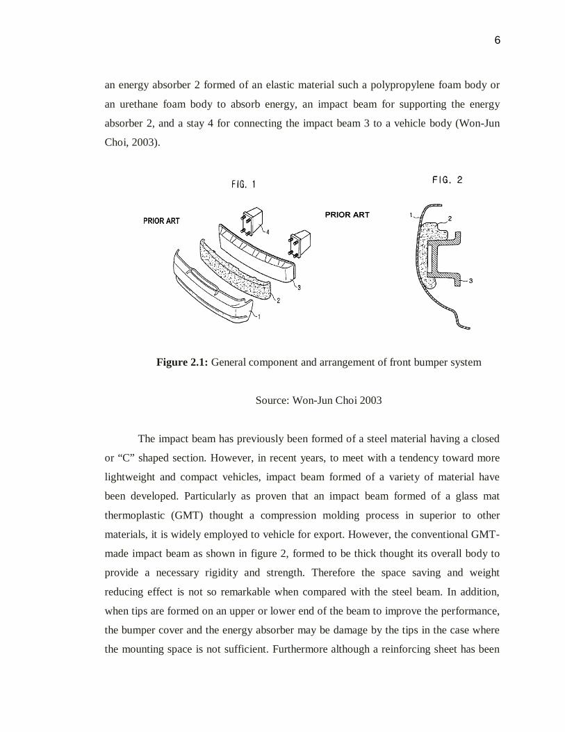
an energy absorber 2 formed of an elastic material such a polypropylene foam body or
an urethane foam body to absorb energy, an impact beam for supporting the energy
absorber 2, and a stay 4 for connecting the impact beam 3 to a vehicle body (Won-Jun
Choi, 2003).
Figure 2.1: General component and arrangement of front bumper system
Source: Won-Jun Choi 2003
The impact beam has previously been formed of a steel material having a closed
or “C” shaped section. However, in recent years, to meet with a tendency toward more
lightweight and compact vehicles, impact beam formed of a variety of material have
been developed. Particularly as proven that an impact beam formed of a glass mat
thermoplastic (GMT) thought a compression molding process in superior to other
materials, it is widely employed to vehicle for export. However, the conventional GMT-
made impact beam as shown in figure 2, formed to be thick thought its overall body to
provide a necessary rigidity and strength. Therefore the space saving and weight
reducing effect is not so remarkable when compared with the steel beam. In addition,
when tips are formed on an upper or lower end of the beam to improve the performance,
the bumper cover and the energy absorber may be damage by the tips in the case where
the mounting space is not sufficient. Furthermore although a reinforcing sheet has been

7
applied to several conventional beams, since there is a need for an additional process for
forming the reinforcing sheet, the manufacturing cost are increased (Won-Jun Choi,
2003).
Figure 2.2: Attachments of foam material
Source: Won-Jun Choi 2003
Meanwhile, the energy absorber 2 is disposed between the bumper cover 1 and
the impact beam 3 to absorb impact energy. When the energy absorber 2 is subject to an
impact greater than its critical elastic force, it crack and must therefore be replaced.
However in the conventional bumper system, since the energy absorber is integrally
formed, the whole bumper system must be replaced, increasing the repairing costs
(Won-Jun Choi, 2003).
An energy absorption and management system for a motor vehicle includes a
bumper interconnected to the vehicle frame through a pair of substantially identical
energy absorbing assemblies or bumper bracket. Each assembly includes an outer
portion and an inner portion. The outer portion has a pair of spaced apart sides which are
interconnected through an actuate segment. The inner portion preferably stepped in a
longitudinally extending direction such that they include first and second substantially

8
horizontal segment which are vertical spaced from one another. If the motor vehicle is
involved in a frontal impact of a predetermined speed, energy is absorbed and managed
though deformation of the outer and inner portions. Deformation of the outer portion is
controlled by the inner portion which is welded or otherwise fixedly attached thereto at
spaced apart points (Ronald S. Kemp, Oxford Nov. 16, 1999).
Figure 2.3: An illustration of bracket attachment
Source: Ronald S. Kemp 1999
2.3 Bumper Hydraulic Absorbing System
A shock-absorbing bumper system for an automotive vehicle includes a conduit
subsystem for conducting hydraulic fluid therein, a supply subsystem for supplying
hydraulic fluid, a pressure balancing subsystem for regulating the pressure of hydraulic
fluid, front and rear bumper subsystem for respectively extending and retracting front
and rear bumper and for absorbing shock, a switching subsystem for directing hydraulic
fluid, and feedback subsystem for absorbing shock (Yang Chin-Hun, Jun 1991).