Improvement in Steering Performance by Push-Pull Operation ...
16
International Journal of Automotive and Mechanical Engineering ISSN: 2229-8649 (Print); ISSN: 2180-1606 (Online) Volume 15, Issue 1 pp. 4919-4934 March 2018 © Universiti Malaysia Pahang, Malaysia DOI: https://doi.org/10.15282/ijame.15.1.2018.4.0383 4919 Improvement in Steering Performance by Push-Pull Operation in Car Driving S. Kajiwara Faculty of Science and Engineering, Kindai University, 3-4-1 Kowakae Higashiosaka, Osaka, Japan Email: [email protected] Phone: +816 43073485; Fax: +816 43073485 ABSTRACT Collision avoidance is one of the most difficult driving operations in the domain of intelligent vehicles. Steering operation error is one of the causes of traffic accidents. Steering operability also contributes greatly to the comfort of drivers and their mental workload during driving. Thus, with comfortable steering operation it is possible to reduce shoulder stiffness and arm fatigue caused by long-time driving. The development of automatic driving vehicles is becoming advanced worldwide. Consequently, the goal is to implement a level 3 automatic driving vehicle for practical use, in which "the system performs the acceleration, the steering, and the braking, and the driver responds when the system requests it". For this system to be practical, when autonomous driving becomes impossible for some reason, it is important to develop a system that allows the driver to be in control regardless of driving experience or age. In conventional round steering wheel, since there is no output muscle directly involved in the direction of movement of the upper limbs, it is difficult to instantaneously exert a large force and control performance is not good. Therefore, a twin lever steering (TLS), which is a push / pull alternate steering system, is proposed in this study. In the proposed TLS, there are output muscles that are directly involved in the direction of movement of the upper limb, including the biceps brachii muscle, and it is conceivable that the motor controllability is higher than in the conventional system. In this research, the superiority of the proposed TLS was verified using an experimental racing kart and driving simulator (DS). Furthermore, using DS, the superiority of a TLS in the steering operation immediately after the cancellation of automatic operation is clear. Keywords: Autonomous car; lever steering; vehicle control; reaction time; mental workload; collision avoidance. INTRODUCTION Mistakes in steering operation are cited as one cause of traffic accidents. Steering operability contributes greatly to the comfort of the driver when driving a car and with a comfortable steering operation [1, 2]; it is possible to reduce shoulder stiffness and arm fatigue caused by long-term driving [3]. Various types of assistances devices were designed to assist lateral control. A classification of those devices based on the combination of two human-automation interaction frameworks is proposed [4]. The development of automatic driving vehicles has advanced worldwide. Level 3 automatic driving vehicles are being put into practical use, in which automatic operation is said to be "a state where all of the acceleration, steering, and braking operations are performed by the system and the system is requested by the driver". In the future, to practically
Transcript of Improvement in Steering Performance by Push-Pull Operation ...
International Journal of Automotive and Mechanical Engineering
ISSN: 2229-8649 (Print); ISSN: 2180-1606 (Online)
Volume 15, Issue 1 pp. 4919-4934 March 2018
© Universiti Malaysia Pahang, Malaysia
DOI: https://doi.org/10.15282/ijame.15.1.2018.4.0383
4919
Improvement in Steering Performance by Push-Pull Operation in Car Driving
S. Kajiwara
Faculty of Science and Engineering, Kindai University,
3-4-1 Kowakae Higashiosaka, Osaka, Japan
Email: [email protected]
Phone: +816 43073485; Fax: +816 43073485
ABSTRACT
Collision avoidance is one of the most difficult driving operations in the domain of
intelligent vehicles. Steering operation error is one of the causes of traffic accidents.
Steering operability also contributes greatly to the comfort of drivers and their mental
workload during driving. Thus, with comfortable steering operation it is possible to
reduce shoulder stiffness and arm fatigue caused by long-time driving. The development
of automatic driving vehicles is becoming advanced worldwide. Consequently, the goal
is to implement a level 3 automatic driving vehicle for practical use, in which "the system
performs the acceleration, the steering, and the braking, and the driver responds when the
system requests it". For this system to be practical, when autonomous driving becomes
impossible for some reason, it is important to develop a system that allows the driver to
be in control regardless of driving experience or age. In conventional round steering
wheel, since there is no output muscle directly involved in the direction of movement of
the upper limbs, it is difficult to instantaneously exert a large force and control
performance is not good. Therefore, a twin lever steering (TLS), which is a push / pull
alternate steering system, is proposed in this study. In the proposed TLS, there are output
muscles that are directly involved in the direction of movement of the upper limb,
including the biceps brachii muscle, and it is conceivable that the motor controllability is
higher than in the conventional system. In this research, the superiority of the proposed
TLS was verified using an experimental racing kart and driving simulator (DS).
Furthermore, using DS, the superiority of a TLS in the steering operation immediately
after the cancellation of automatic operation is clear.
Keywords: Autonomous car; lever steering; vehicle control; reaction time; mental
workload; collision avoidance.
INTRODUCTION
Mistakes in steering operation are cited as one cause of traffic accidents. Steering
operability contributes greatly to the comfort of the driver when driving a car and with a
comfortable steering operation [1, 2]; it is possible to reduce shoulder stiffness and arm
fatigue caused by long-term driving [3]. Various types of assistances devices were
designed to assist lateral control. A classification of those devices based on the
combination of two human-automation interaction frameworks is proposed [4]. The
development of automatic driving vehicles has advanced worldwide. Level 3 automatic
driving vehicles are being put into practical use, in which automatic operation is said to
be "a state where all of the acceleration, steering, and braking operations are performed
by the system and the system is requested by the driver". In the future, to practically

Improvement in Steering Performance by Push-Pull Operation in Car Driving
4920
implement a level 3 automatic driving system, in the event that automatic driving
becomes impossible for some reason, and the system is required to become redundant,
the development of a system that the driver can control regardless of driving experience
and age becomes important. Considering this, a steering operation system that has high
motion controllability and enables a space-saving layout compared with the conventional
steering wheel, such as a twin lever steering (TLS) [5] is useful. Upper limb movement
can be considered motion in a two-dimensional plane composed of a shoulder joint, an
elbow joint, and a carpal joint. In the case of round steering, the steering operation is
performed by vertical movement. For this reason, a strong force is required to maintain
the constant steering angle of turn during cornering. On the other hand, since the TLS
operates the steering with a normal (forward and backward) motion, the steering angle
can be maintained with a weaker force. In some cases, the body movement during steering
operation was analyzed using a musculoskeletal model. Regarding the musculoskeletal
model of the upper limb, it has also been reported that it is modeled as a three-dimensional
seven-degree of freedom system linked to the shoulder [6]. A driver's muscle activation
strategy during driving was validated using a mathematical model by measuring the driver
muscle activity using electromyography (EMG) [7]. It was revealed that hand rigidity
depends on the posture of the arm by measuring the hand-tip displacement and the hand-
end force immediately after applying the forced displacement [8].
In normal round steering, it has been reported that the standard deviation of the
arm positioning error when the elbow flexion angle is π/2 is about 0.07 rad [9]. This error
is 0.11 rad when converted to a steering angle with an elbow length of 0.3 m and a steering
wheel radius of 0.19 m. That is difficult to control since the initial response of steering
straight ahead falls within the range of 0.11 rad [10]. Therefore, in order to steer with an
accuracy less than this error, a steering reaction force is necessary. However, the control
resolution is considered to be high in the longitudinal direction. Furthermore, to study the
redundancy of automatic driving vehicles, we examine the safety and usefulness of a TLS
and ordinary round type steering. A number of level 2 automatic driving vehicles are in
practical use and the practical application of level 3 vehicles is currently being studied.
Automatic driving level 3 is a state in which the driver and the automatic driving system
coexist to perform the driving operation. Resuming manual control is not only a problem
of action performance but is also related to the reorganization of drivers’ visual strategies
linked to drivers’ disengagement from the steering task. Assistance designers should pay
attention to potential changes in drivers’ activity when carrying out development work
on highly automated vehicles [11]. Automation promotes extended eyes-off-road
behavior that may lead to a loss of situational awareness degrading a driver's ability to
detect hazards and make necessary overrides [12]. In order to cope with level 3 automatic
driving, it is necessary to develop a system that can safely change the driving control to
the driver in an emergency situation where human judgment is necessary.
In other words, it is necessary to consider the steering operation performance
immediately after the automatic operation is canceled. Even with manual operation, the
reaction time is extended when conducting a selection reaction instructing different
operation directions by stimulation. The operations carried out by the driver at the time
of driving are accelerator, brake, and left and right turning operations. It is estimated that
the reaction time for this driving behavior is longer than in the case of the simple reaction
because the driver must select one of the operations and continue it. In addition, as the
driver is influenced by the number of choices, Hick's law that the reaction time is
prolonged in proportion to the base 2 logarithm of the number of alternatives is said to be
established under simple circumstances. It was reported that large-scale data (N = 321)

Kajiwara / International Journal of Automotive and Mechanical Engineering 15(1) 2018 4919-4934
4921
of simple brake reaction maneuvering times by presenting a beat sound from the outside
of the vehicle when traveling on a general road in a real car and using a small sample
[13]. The result shows that the 25 % of the total number of drivers seem to take at least
1.2 seconds before a braking operation. Another study indicated that the perceived time
in the unexpected situation is extended from 0.4 to 1.0 second and the travel time is
extended from 0.3 seconds to 0.8 seconds in a test course using an actual vehicle [14]. In
most European countries, to avoid accidents when a car travelling in front suddenly stops
or decreases in speed, it is advised that the driver of each vehicle must maintain a
sufficient distance using either the 2-second rule or half distance rule. The 2-second rule
is frequently used as a rule of thumb and is taught at driving schools. Some devices (such
as road signs) are used to help the driver follow these rules [15].
In this research, the proposed TLS is designed and manufactured using slide rails,
mounted on a laboratory racing kart, and a real test run on a circuit is carried out. Kart is
used for car driving [16]. Furthermore, a running test on a DS is performed using a handle
controller remodeled to a TLS. From the results, the steering operation performance of
the conventional steering wheel and the TLS is examined. Furthermore, the steering
operation immediately after the cancellation of automatic operation using DS is
considered. At that time, we verify the possibility that the driver cannot respond to the
sudden change from autonomous control to driver control in an adequate time is verified,
thereby creating a dangerous situation.
AUTOMOBILE STEERING MODEL
It is considered that a human being detects the environment such as the road and the
motion condition of a car body and performs the steering operation based on the target
exercise situation. The block diagram for this steering operation is shown in Figure 1. A
signal is transmitted from the brain to the muscles of the arm, and the steering wheel is
then actually operated. Both the biceps brachii and triceps brachii muscles function during
the steering operation. These are called bipartite muscles and refer to the muscles
straddling the shoulder and the elbow. In addition, a forearm muscle also functions when
gripping the steering wheel. Among the forearm muscles, the superficial flexors are
greatly involved in the bending motion of the fingers. In this study, we focused on the
biceps brachii, which is a bipartite muscle that functions during steering operation and
the superficial flexor muscle, which functions when gripping a steering wheel.
Upper limb movement can be considered motion in a two-dimensional plane
composed of the shoulder joint (S), elbow joint (E), and carpal joint (W). The motion
direction of the upper limb is shown in Figure 2. In the circle whose radius is the distance
between the shoulder joint (S) and the carpal joint (W), as in the case of a round steering,
the steering operation is performed with vertical direction. For this reason, it is
conceivable that a strong grip force is required to maintain a constant steering angle of
turn while turning. On the other hand, a TLS performs a steering operation with
movement in the normal direction (forward and backward). Therefore, we can maintain
the steering angle with weaker grip strength.

Improvement in Steering Performance by Push-Pull Operation in Car Driving
4922
Figure 1. Block diagram for this steering operation.
Figure 2. Motion direction of the upper limb.
AUTOMOBILE STEERING MODEL
The experimental racing kart and the handle controller for DS were also converted to a
TLS, enabling operation with a front and rear alternate steering TLS.
Racing Kart Overview
In this research, Winforce TIA, a Yamaha racing kart, was used as the experimental
vehicle. This racing kart has a total length of 1680 mm, a wheelbase of 1040 mm, a
maximum full width of 1300 mm, and a dry weight of 58 kg including the engine. The
engine is equipped with Yamaha's KT100SD. The braking system is of the hydraulic disk
type and is mounted only on the rear wheels. The Winforce TIA is shown in Figure 3.
Table 1 shows the specifications of Winforce TIA and KT100SD.

Kajiwara / International Journal of Automotive and Mechanical Engineering 15(1) 2018 4919-4934
4923
Figure 3. Racing cart: Winforce TIA.
Table 1. Specifications of cart; Winforce.
Parameters Specification
Total length/Axis Distance 1680/1040 mm
Track F/R Standard; 1000/1300 mm
Dry weight 58 kg (including the engine)
Toe 0 – 1°
Frame Type Dia.30 mm chrome-molybdenum
steel frame
Front tire 10×3.60-5(SL83)
Rear tire 11×6.00-5(SL83)
Braking system: Rear only Hydraulic disc
Steering system Directly connected with single stem
Engine type 2-stroke, air-cooled, piston valves
Cylinder number / Array / Displacement Single-cylinder / Forward /97.6 cc
Bore x stroke 52.0 x 46.0 mm
Compression ratio 7.9
Starting system Flocked
Lubrication system Mixed gasoline (25: 1)
Fuel tank capacity 8 ℓ
Ignition system T.C.I.
Spark plug NGK B9EV
Carburetor WALBRO WB-3A
Clutch Direct
Design and Production of TLS for Racing Kart
The TLS was designed and manufactured using a 3590 slide pack FBW made by Linear
Guide THK. The stay to which the linear guide is attached consisted of a hollow pipe
welded to the frame of the racing kart, and the distance between the rails was determined
according to shoulder width. The experimental apparatus consists of Grip part, arm part
combined hollow pipe, square pipe. The schematic of the assembly is shown in Figure 4.
In addition, in consideration of safety when performing the experiment, a Sparco 6 point
seat belt was mounted. The TLS that achieved perfect front and rear alternate steering is

Improvement in Steering Performance by Push-Pull Operation in Car Driving
4924
mounted on a laboratory racing kart as shown in Figure 5 (a), and the view from above is
shown in Figure 5 (b).
Figure 4. Schematic view of twin lever steering.
(a) (b)
Figure 5. Racing kart with TLS steering system (a) overview and; (b) steering
components.
The round steering of normal racing kart is a 3-spoke steering with an outside
diameter of 290 mm. In this racing kart, the Ackermann mechanism is adopted for the
steering mechanism, and the mechanism that connects the steering and the steering shaft
is both a direct steering type and a round type steering. The proposed TLS achieved the
same cutting angle as ordinary steering. In the TLS, the maximum break angle was
obtained at around 220 mm from the neutral point, and in round steering, the maximum
break angle was set at 90°. Figure 6 compares the TLS and round steering angle. The
steering angle of TLS system is shown in Figure 6 (a) and the steering angle of round
type steering system is shown in Figure 6 (b), respectively. The steering angle θ was set
to 30° for both machines.
TLS Control of Handle Controller
In order to achieve a complete forward and backward alternate steering TLS in DS, the
steering wheel controller was remodeled. The G25 Racing Wheel made by Logitech was
used as the handle controller. First, the steering wheel controller was attached upwards
and the steering wheel was removed, then the same control as the TLS on the
experimental racing kart was installed. The TLS experiment in DS is shown in Figure 7.

Kajiwara / International Journal of Automotive and Mechanical Engineering 15(1) 2018 4919-4934
4925
(a) (b)
Figure 6. Angle of the front wheel θ (a) TLS system and: (b) round steering.
Figure 7. TLS experiment in DS.
AUTOMOBILE STEERING MODEL
Experimental Method and Results
In this study, the superiority of TLS would be clarified by running experiments; the
relevance of the running experiment to the DS experiment is also examined. First, a real
running test is carried out in the experimental racing kart. Myoelectric potential
measurement and lap time measurement is performed simultaneously. Next, myopotential
measurement and lap time measurement of the subject are also performed in the DS.
Myoelectric potential is the voltage that occurs when moving a muscle. How much and
how the muscle action potential occurred was investigated.
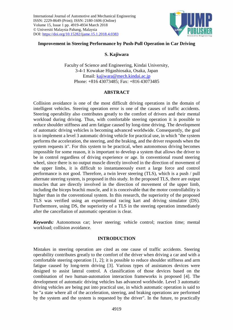
In this experiment, ProComp 5 Infiniti, an encoder manufactured by Thought
Technology Ltd, which is a multi-channel battery-driven device for data collection, was
used. This measurement system is shown in Figure 8. A myoelectric electrode was
attached with surgical tape. The black electrode is the body earth, and the blue and yellow
electrodes are the anode and the cathode. At the time of measurement, noise was removed
by wiping the measurement site with alcohol and mounting a disposable electrode on the
myoelectric electrode. During measurement, myoelectric electrodes were attached to the
biceps brachii muscle that generates the muscle force of the arm and the superflexi flexor
θ θ
Improvement in Steering Performance by Push-Pull Operation in Car Driving
4926
muscle that generates the grip strength. Measurements were carried out for both the TLS
and round steering. The subject was a 22-year-old male and experiments were conducted
on a course of 20 laps.
Figure 8. Schematic of EMG measurement system.
Experimental Test Course
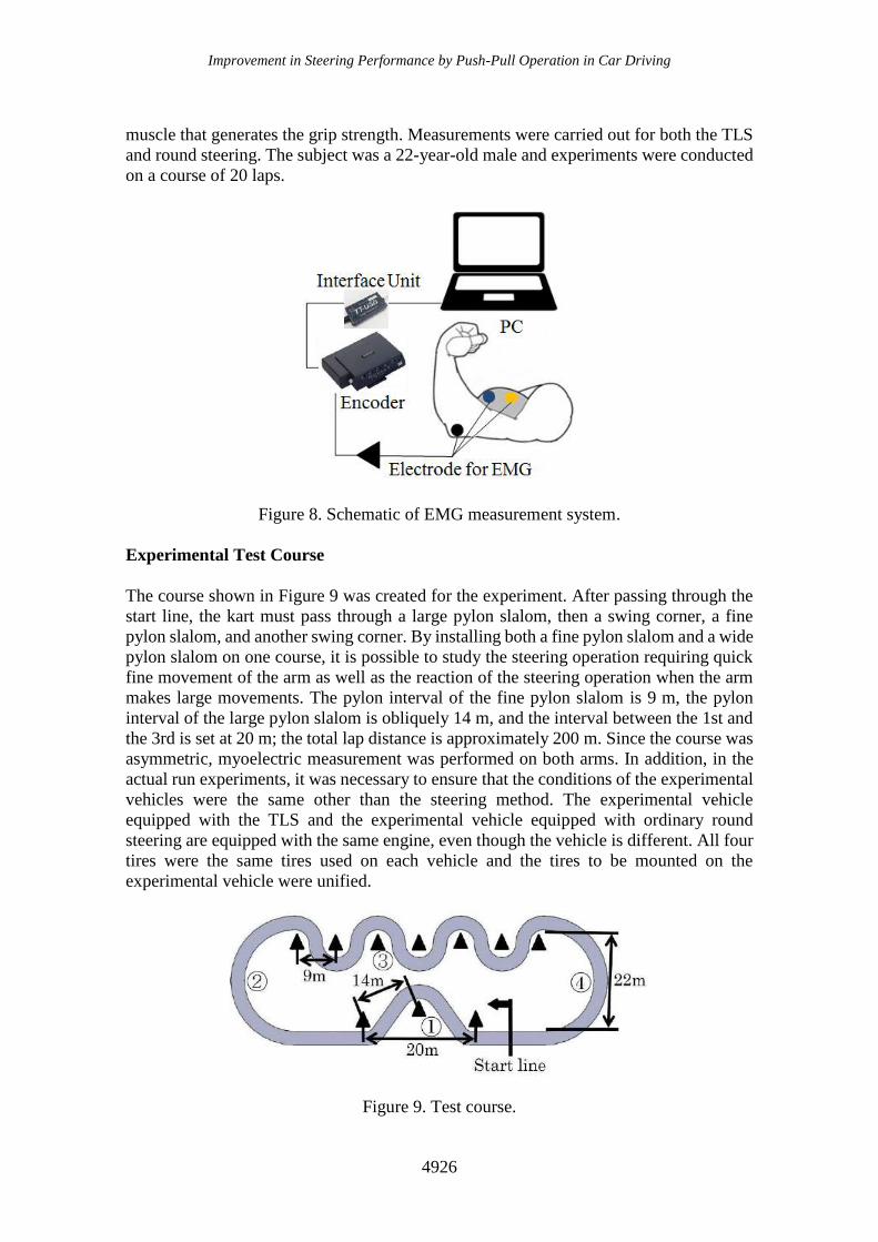
The course shown in Figure 9 was created for the experiment. After passing through the
start line, the kart must pass through a large pylon slalom, then a swing corner, a fine
pylon slalom, and another swing corner. By installing both a fine pylon slalom and a wide
pylon slalom on one course, it is possible to study the steering operation requiring quick
fine movement of the arm as well as the reaction of the steering operation when the arm
makes large movements. The pylon interval of the fine pylon slalom is 9 m, the pylon
interval of the large pylon slalom is obliquely 14 m, and the interval between the 1st and
the 3rd is set at 20 m; the total lap distance is approximately 200 m. Since the course was
asymmetric, myoelectric measurement was performed on both arms. In addition, in the
actual run experiments, it was necessary to ensure that the conditions of the experimental
vehicles were the same other than the steering method. The experimental vehicle
equipped with the TLS and the experimental vehicle equipped with ordinary round
steering are equipped with the same engine, even though the vehicle is different. All four
tires were the same tires used on each vehicle and the tires to be mounted on the
experimental vehicle were unified.
Figure 9. Test course.

Kajiwara / International Journal of Automotive and Mechanical Engineering 15(1) 2018 4919-4934
4927
Kart Running Test Results
The comparison between the lap times for normal round steering and TLS is shown in
Figure 10. The average lap time for the entire lap was 0.64 seconds faster for the TLS. In
addition, after ten laps, the lap times became faster due to familiarity with the TLS. On
the other hand, with the normal round steering, the lap time was slower due to fatigue of
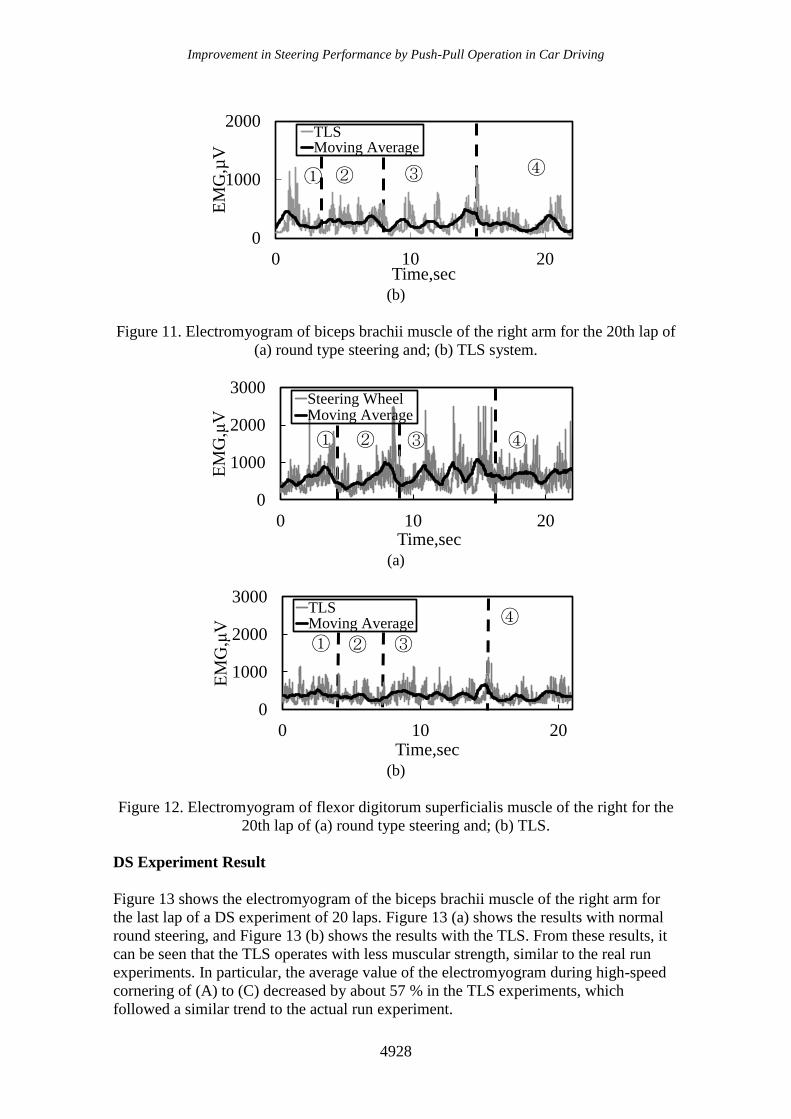
the arm. The final lap time was 3.13 seconds faster for the TLS. Figure 11 shows the
electromyogram of biceps brachii muscle of the right arm for the last lap of 20-lap
experiment. In addition, the electromyogram of the bipod muscle of the right arm for the
20th lap is shown in Figure 12.
Figure 11 (a) shows the results of the normal round steering, and Figure 11 (b)
shows the results with the TLS. For smoothing, the data was subjected to moving average
processing for 1 second. In Figure 12 and Figure 13, the moving average line is
represented by the solid black line, (A)-(C) represents the mark number in Figure 10. For
example, in Figure 10, the marked part of (B) is a pylon slalom, which corresponds to (B)
in Figure 11 and Figure 12. These figures show that the TLS requires less muscle strength
than round steering. In particular, from Figure 11, the average value of the
electromyogram during high-speed cornering of (A) and (C) was reduced by about 52 %
with the TLS, and a large difference was observed. From Figure 12, it can be seen that
the rounded steering shows a significant change in myoelectric potential throughout the
lap. On the other hand, the TLS changes little by one turn. By adopting the TLS, it can be
seen that the grip strength required during operation is less than for normal round steering.
The average value of the myoelectric potential of the whole lap decreased by about 43 %
using the TLS, and it was observed that the TLS was operated with about 1/2 of the grip
force of round steering.
Figure 10. Comparison between the lap times for normal round steering and TLS.
(a)
21
23
25
1 10.5 20
Lap
tim
e,se
c
Number of laps
Normal steering wheel
TLS
10
0
1000
2000
0 10 20
EM
G,µ
V
Time,sec
Steering WheelMoving Average
① ② ③ ④
Improvement in Steering Performance by Push-Pull Operation in Car Driving
4928
(b)
Figure 11. Electromyogram of biceps brachii muscle of the right arm for the 20th lap of
(a) round type steering and; (b) TLS system.
(a)
(b)
Figure 12. Electromyogram of flexor digitorum superficialis muscle of the right for the
20th lap of (a) round type steering and; (b) TLS.
DS Experiment Result
Figure 13 shows the electromyogram of the biceps brachii muscle of the right arm for
the last lap of a DS experiment of 20 laps. Figure 13 (a) shows the results with normal
round steering, and Figure 13 (b) shows the results with the TLS. From these results, it
can be seen that the TLS operates with less muscular strength, similar to the real run
experiments. In particular, the average value of the electromyogram during high-speed
cornering of (A) to (C) decreased by about 57 % in the TLS experiments, which
followed a similar trend to the actual run experiment.
① ② ③ ④
0
1000
2000
0 10 20
EM
G,µ
V
Time,sec
TLSMoving Average
① ② ③ ④
0
1000
2000
3000
0 10 20
EM
G,μ
V
Time,sec
Steering WheelMoving Average
① ② ③
④
0
1000
2000
3000
0 10 20
EM
G,μ
V
Time,sec
TLSMoving Average
Kajiwara / International Journal of Automotive and Mechanical Engineering 15(1) 2018 4919-4934
4929
(a)
(b)
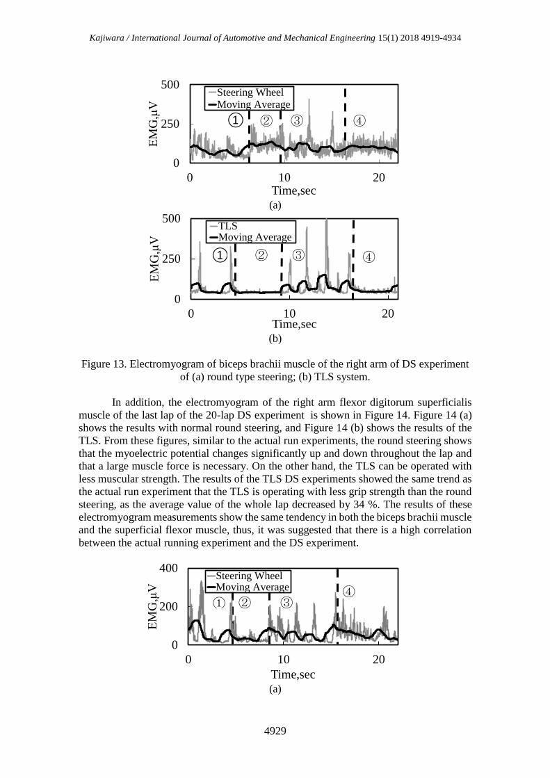
Figure 13. Electromyogram of biceps brachii muscle of the right arm of DS experiment
of (a) round type steering; (b) TLS system.
In addition, the electromyogram of the right arm flexor digitorum superficialis
muscle of the last lap of the 20-lap DS experiment is shown in Figure 14. Figure 14 (a)
shows the results with normal round steering, and Figure 14 (b) shows the results of the
TLS. From these figures, similar to the actual run experiments, the round steering shows
that the myoelectric potential changes significantly up and down throughout the lap and
that a large muscle force is necessary. On the other hand, the TLS can be operated with
less muscular strength. The results of the TLS DS experiments showed the same trend as
the actual run experiment that the TLS is operating with less grip strength than the round
steering, as the average value of the whole lap decreased by 34 %. The results of these
electromyogram measurements show the same tendency in both the biceps brachii muscle
and the superficial flexor muscle, thus, it was suggested that there is a high correlation
between the actual running experiment and the DS experiment.
(a)
① ② ③ ④
0
250
500
0 10 20
EM
G,μ
V
Time,sec
Steering WheelMoving Average
① ② ③ ④
0
250
500
0 10 20
EM
G,μ
V
Time,sec
TLSMoving Average
① ② ③ ④
0
200
400
0 10 20
EM
G,μ
V
Time,sec
Steering WheelMoving Average

Improvement in Steering Performance by Push-Pull Operation in Car Driving
4930
(b)
Figure 14. Electromyogram of flexor digitorum superficialis muscle of the right of DS
experiment of (a) round type steering; (b) TLS system.
Comparison of Lap Time and Operation Range
Next, lap times and distance moved by hand were compared during round steering and
TLS operation. The range of motion of the steering wheel was changed by adjusting the
cutting angle of the G25 Racing Wheel. Since the round steering wheel has a diameter of
275 mm, the moving distance was calculated from the cutting angle. The average value
of five laps was calculated. The lap time and operation range of the round steering were
compared with those of the TLS. The relationship between the operating range and lap
time is shown in Figure 15. From this figure, it can be seen that there is a difference in
the operating range of motion between the TLS and round steering. The fastest lap time
for the TLS was in the range of 150 mm whereas for the round steering the fastest lap
time was 350 mm, which was more than twice the difference. For the fastest lap time, the
TLS was about 0.3 s faster. From this result, it was found that the TLS could obtain a fast
lap time with less operation range. That is, it is estimated that the control resolution of the
arm has improved by adopting the TLS.
Figure 15. Relationship between the operating range and lap time.
REDUNDANT EXPERIMENT OF AUTONOMOUS CAR OPERATION
Thus far, real run experiments and DS experiments were conducted, and there was a high
correlation between the results. Moreover, the possibility of obtaining high control
21
22
23
50 150 250 350 450
Lap
Tim
e,se
c
Distance to move the hand,mm
TLS
Normal Steering Wheel
① ② ③ ④
0
200
400
0 10 20
EM
G,μ
V
Time,sec
TLSMoving Average

Kajiwara / International Journal of Automotive and Mechanical Engineering 15(1) 2018 4919-4934
4931
resolution with less muscular strength was indicated by adopting the TLS. The
redundancy of automatic driving vehicles was examined by using the result of the
experiments. Level 2 automatic driving vehicles are already in practical use, and the
practical application of level 3 vehicles is currently being studied. Automatic driving level
3 is a state in which the driver and the automatic driving system coexist to perform the
driving operation. In order to achieve level 3 automatic driving, it is necessary to develop
a system that safely changes the driving to the driver in an emergency situation where
human judgment is necessary. In other words, it is necessary to consider the steering
operation performance immediately after the automatic operation is canceled. Therefore,
the safety and usefulness of the TLS and normal round steering are examined. At that
time, the possibility that the driver cannot respond to the sudden change from autonomous
control to driver control in an adequate time is verified, thereby creating a dangerous
situation.
Redundancy Experiment Method
In this experiment, automatic operation was reproduced using the AI (Artificial
Intelligence) function of DS. The safety and usefulness of the TLS and normal round
steering immediately after the release of automatic operation was examined and the
feasibility of Level 3 automatic driving vehicle was considered. It is necessary to
determine the delay time when switching from automatic operation to manual operation.
Therefore, the delay time was calculated from the stop time of general car. The stop time
is calculated as the sum of the reaction time and the brake time. The reaction time is the
time from when it is judged that it is necessary for the driver to apply the brake and the
brake starts to be effective, and the usual average reaction time is 0.75 second [18]. In
addition, the braking time is the time from the start of braking until stopping and can be
calculated from Eq. (1).
tb =v0
mg (1)
where tb is braking time, v0 is velocity before braking, m is the coefficient friction
between the road surface and the tire and g is the gravity acceleleration.
Here, the vehicle speed before braking when traveling on an ordinary road is
assumed to be 50 km/h. The coefficient of friction of the road surface was 0.7, which is
the friction coefficient of dry asphalt. The stop time was calculated and found to be about
3 seconds. Since the stop time while traveling at 50 km/h is about 3 s, even when there is
redundancy of automatic operation, it is presumed that there is a high possibility that
danger can be avoided if the system requests an operation change 3 s before, therefore a
3 s grace time was considered in this study.
In the experiment, assuming that the driver fell asleep during autonomous driving,
the subject closed their eyes in both the round steering wheel and the TLS experiments,
and started the AI running with their hands released from the steering wheel and the lever.
The subject was signaled 3 s before the driving change. The subject judged the
information on the screen with a grace period of 3 s and held the handle or the lever for
manual driving. Thease experiments were conducted in randam conditions for emergency
avoidance. To make the story simple, these examination were used only control of
steering wheel or TLS, but these were not used the brakes. This measurement was
performed five times and the number of successful outcomes without spinning was
Improvement in Steering Performance by Push-Pull Operation in Car Driving
4932
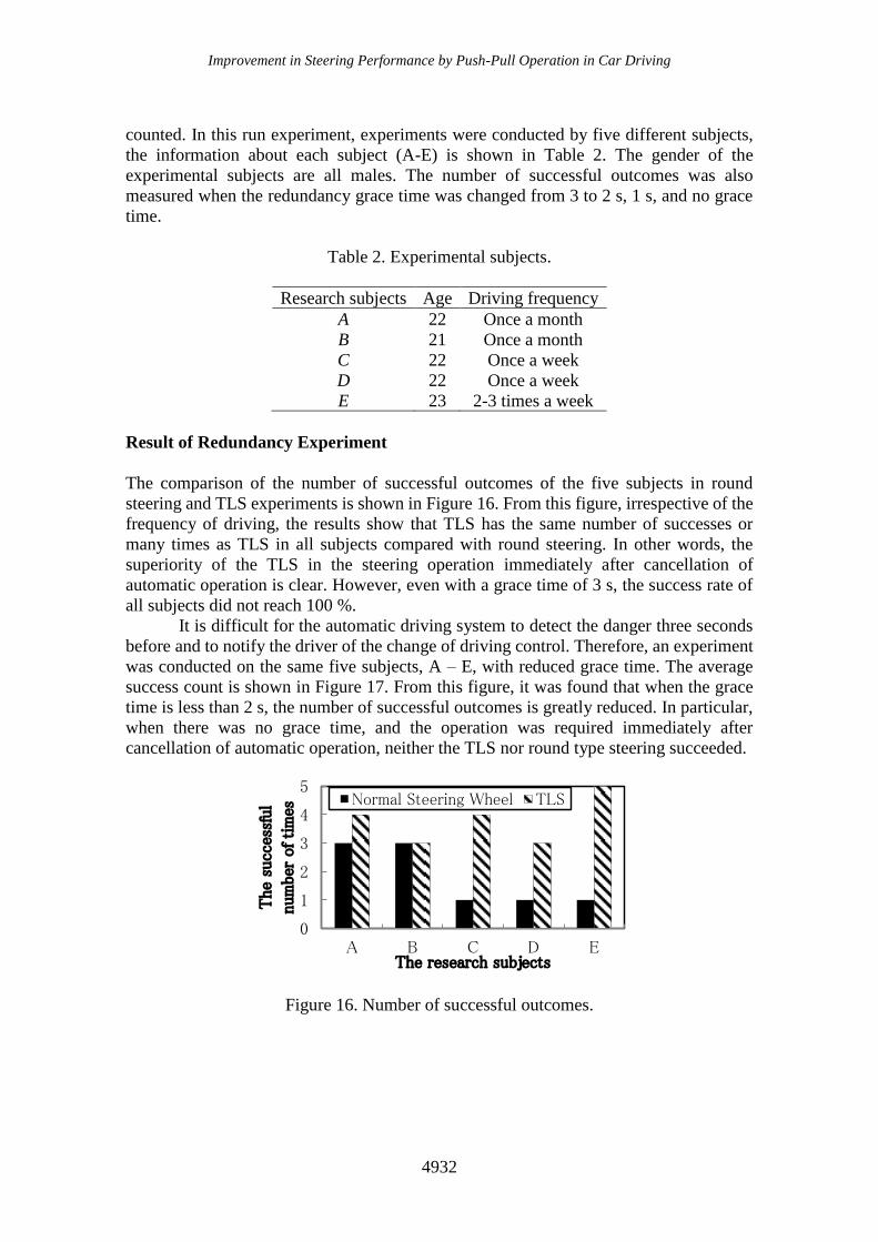
counted. In this run experiment, experiments were conducted by five different subjects,
the information about each subject (A-E) is shown in Table 2. The gender of the
experimental subjects are all males. The number of successful outcomes was also
measured when the redundancy grace time was changed from 3 to 2 s, 1 s, and no grace
time.
Table 2. Experimental subjects.
Research subjects Age Driving frequency
A 22 Once a month
B 21 Once a month
C 22 Once a week
D 22 Once a week
E 23 2-3 times a week
Result of Redundancy Experiment
The comparison of the number of successful outcomes of the five subjects in round
steering and TLS experiments is shown in Figure 16. From this figure, irrespective of the
frequency of driving, the results show that TLS has the same number of successes or
many times as TLS in all subjects compared with round steering. In other words, the
superiority of the TLS in the steering operation immediately after cancellation of
automatic operation is clear. However, even with a grace time of 3 s, the success rate of
all subjects did not reach 100 %.
It is difficult for the automatic driving system to detect the danger three seconds
before and to notify the driver of the change of driving control. Therefore, an experiment
was conducted on the same five subjects, A – E, with reduced grace time. The average
success count is shown in Figure 17. From this figure, it was found that when the grace
time is less than 2 s, the number of successful outcomes is greatly reduced. In particular,
when there was no grace time, and the operation was required immediately after
cancellation of automatic operation, neither the TLS nor round type steering succeeded.
Figure 16. Number of successful outcomes.
0
1
2
3
4
5
A B C D E
The
succ
essf
ul
num
ber
of tim
es
The research subjects
Normal Steering Wheel TLS

Kajiwara / International Journal of Automotive and Mechanical Engineering 15(1) 2018 4919-4934
4933
Figure 17. Average number of success times.
CONCLUSION
We studied the superiority of twin lever steering (TLS) as a new operation method. The
following conclusions can be drawn from this study.
a) Compared to conventional round steering, TLS uses less muscular strength, so
that arm fatigue is less likely to occur even when the number of laps increases.
b) The myoelectric potential measurement result and the lap time result are similar
and related in both real run and DS experiments.
c) In the experiments that considered a steering operation immediately after the
cancellation of automatic operation, the TLS had more successful outcomes than
conventional round steering and superiority was confirmed when there was a
grace time of over 2 s.
d) It is difficult to steer safely when the steering operation is required to occur within
1 second of the cancellation of automatic operation.
e) When there was no time delay (0 s grace time), the number of successes was zero
with any of the handles.
In the future, it is considered necessary to optimize the steering performance by
changing the steering mechanism to the TLS. Also, since there could be differences in
response time from when a stimulus is presented to stepping on brake pedal due to age or
gender, it is necessary to collect large scale data that includes gender and age
characteristics.
REFERENCES
[1] Hancock PA, Verwey WB. Fatigue, workload and adaptive driver systems.
Accident Analysis & Prevention. 1997; 29 (4): 495-506. doi : 10.1016/S0001-
4575(97)00029-8.
[2] Zulkarnain N, Zamzuri H, Mazlan SA. Ride and Handling Analysis for an Active
Anti-Roll Bar: Case Study on Composite Nonlinear Control Strategy.
International Journal of Automotive and Mechanical Engineering. 2014;10:2122-
242.
[3] Wintera CF, Marieke RH, Martensb H, Stantond NA. Effects of adaptive cruise
control and highly automated driving on workload and situation awareness: A
0
1
2
3
4
5
0 1 2 3 4
Av
erag
e S
ucc
ess
Tim
es
Time to Notice, sec
TLS
Normal Steering Wheel
Improvement in Steering Performance by Push-Pull Operation in Car Driving
4934
review of the empirical evidence. Transportation. Research Part F: Traffic
Psychology and Behaviour. 2014; 27: 196-217. doi: 10.1016/j.trf.2014.06.016.
[4] Young MS, Stanton NA. Malleable attentional resources theory: A new
explanation for the effects of mental underload on performance. Human Factors.
2002; 44: 365-375.
[5] Tajima T, Tada Y, Nakamura Y, Tamura N. Development of the Next-Generation
Steering System (Development of the Twin Lever Steering for Production
Vehicle) SAE Internationl Journal Passenger Cars – Mechanics System. 2011; 4-
1: 370-383. doi: 10.4271/2011-01-0557.
[6] Pennestri E, Stefanelli R, Valentini PP, Vita L. Virtual musculo-skeletal model
for the biomechanical analysis of the upper limb, Journal of Biomechanics, 2007;
40: 1350-1361. doi: 10.1016/j.jbiomech.2006.05.013.
[7] Pick AJ, Cole DJ. Measurement of Driver Steering Torque Using
Electromyography. Journal of Dynnamics System and Measurement Control .
2006; 128: 960-968. doi:10.1115/1.2363198.
[8] Mussa-Ivaldi FA, Hogan N, Bizzi E. Neural, Mechanical and Geometric Factors
Subserving Arm Posture in Humans. The Journal of Neuroscience, 1985; 10:
2732-2743.
[9] Akamatsu M, Hirasawa S, Hayashi Y. Kansetsu kankaku no kansetstu
kakudo•sokudo niyoru chigai nitsuite. Dai 7 kai baiomekanizumu
gakujyutukouenkai yokoushu: 1986; 61-64 (in Japanese).
[10] Sakai H. Stability under force control and its index, Transactions of Society of
Automotive Engineers of Japan, 2013; 44: 441-448 (in Japanese).
[11] Navarro J, Françoisa M, Mars F. Obstacle avoidance under automated steering:
Impact on driving and gaze behaviours. Transportation Research Part F: Traffic
Psychology and Behaviour. 2016; 43: 315-324, doi: 10.1016/j.trf.2016.09.007.
[12] Glaser Y, Llaneras R, Glaser D, Green C. Relationship Between Driver Eyes-Off-
Road Interval and Hazard Detection Performance Under Automated Driving. SAE
Technical Paper. 2016; 2016-01-1424. doi: 10.4271/2016-01-1424.
[13] Johansson G, Rumar K. Drivers' brake reaction time. Human Factors. 1971; 13:
23-27.
[14] Olson PL, Sivak M. Perception-response time to unexpected road way hazards.
Human Factors. 1986; 28: 91-96.
[15] Ziedman K. Drivers performance data book. DOT-HS-807-121, National
Highway Traffic Safety Administration. Information processing. In R. L.
Henderson (Ed.) : 1987; 5.0-5.78.
[16] Abdullah1 NAZ, Sani M.S.M., Husain N.A., Rahman M.M. Zaman I. Dynamics
properties of a Go-kart chassis structure and its prediction improvement using
model updating approach. International Journal of Automotive and Mechanical
Engineering. 2017; 14: 3887-3897. doi: 10.15282/ijame.14.1.2017.6.0316.
[17] Kumamoto M, Oshima T, Yamamoto T. Control properties induced by the
existence of antagonistic pairs of bi-articular muscles - Mechanical engineering
model analyses. Human Movement Science, 1994; 13: 611-634.
[18] Johansson G, Rumar K. Drivers' brake reaction time. Human Factors. 1971, 13:
23-27.