Improved High Temperature Solar Absorbers for use in ... · producing more efficient solar...
43
SANDIA REPORT SAND2010-7080 Unlimited Release Printed October 2010 Improved High Temperature Solar Absorbers for use in Concentrating Solar Power Central Receiver Applications Andrea Ambrosini, Timothy N. Lambert, Chad L. Staiger, Aaron C. Hall, Marlene Bencomo, Ellen B. Stechel Prepared by Sandia National Laboratories Albuquerque, New Mexico 87185 and Livermore, California 94550 Sandia National Laboratories is a multi-program laboratory managed and operated by Sandia Corporation, a wholly owned subsidiary of Lockheed Martin Corporation, for the U.S. Department of Energy's National Nuclear Security Administration under contract DE-AC04-94AL85000. Approved for public release; further dissemination unlimited.
Transcript of Improved High Temperature Solar Absorbers for use in ... · producing more efficient solar...

SANDIA REPORT SAND2010-7080Unlimited Release Printed October 2010
Improved High Temperature Solar Absorbers for use in Concentrating Solar Power Central Receiver Applications Andrea Ambrosini, Timothy N. Lambert, Chad L. Staiger, Aaron C. Hall, Marlene Bencomo, Ellen B. Stechel Prepared by Sandia National Laboratories Albuquerque, New Mexico 87185 and Livermore, California 94550 Sandia National Laboratories is a multi-program laboratory managed and operated by Sandia Corporation, a wholly owned subsidiary of Lockheed Martin Corporation, for the U.S. Department of Energy's National Nuclear Security Administration under contract DE-AC04-94AL85000.
Approved for public release; further dissemination unlimited.
2
Issued by Sandia National Laboratories, operated for the United States Department of Energy by Sandia Corporation. NOTICE: This report was prepared as an account of work sponsored by an agency of the United States Government. Neither the United States Government, nor any agency thereof, nor any of their employees, nor any of their contractors, subcontractors, or their employees, make any warranty, express or implied, or assume any legal liability or responsibility for the accuracy, completeness, or usefulness of any information, apparatus, product, or process disclosed, or represent that its use would not infringe privately owned rights. Reference herein to any specific commercial product, process, or service by trade name, trademark, manufacturer, or otherwise, does not necessarily constitute or imply its endorsement, recommendation, or favoring by the United States Government, any agency thereof, or any of their contractors or subcontractors. The views and opinions expressed herein do not necessarily state or reflect those of the United States Government, any agency thereof, or any of their contractors. Printed in the United States of America. This report has been reproduced directly from the best available copy. Available to DOE and DOE contractors from U.S. Department of Energy Office of Scientific and Technical Information P.O. Box 62 Oak Ridge, TN 37831 Telephone: (865) 576-8401 Facsimile: (865) 576-5728 E-Mail: [email protected] Online ordering: http://www.osti.gov/bridge Available to the public from U.S. Department of Commerce National Technical Information Service 5285 Port Royal Rd. Springfield, VA 22161 Telephone: (800) 553-6847 Facsimile: (703) 605-6900 E-Mail: [email protected] Online order: http://www.ntis.gov/help/ordermethods.asp?loc=7-4-0#online
3
SAND2010-7080 Unlimited Release
Printed October 2010
Improved High Temperature Solar Absorbers for use in Concentrating Solar Power Central Receiver Applications
Andrea Ambrosini,1 Timothy L. Lambert,1 Chad L. Staiger,1 Aaron C. Hall,2 Marlene Bencomo,1 Ellen B. Stechel1
1 Materials, Devices & Energy Tech, Org. 6364
2 Multiscale Metallurgical S&T, Org. 1831 Sandia National Laboratories
P.O. Box 5800 Albuquerque, New Mexico 87185-MS0734
Abstract
Concentrating solar power (CSP) systems use solar absorbers to convert the heat from sunlight to electric power. Increased operating temperatures are necessary to lower the cost of solar-generated electricity by improving efficiencies and reducing thermal energy storage costs. Durable new materials are needed to cope with operating temperatures >600ºC. The current coating technology (Pyromark High Temperature paint) has a solar absorptance in excess of 0.95 but a thermal emittance greater than 0.8, which results in large thermal losses at high temperatures. In addition, because solar receivers operate in air, these coatings have long term stability issues that add to the operating costs of CSP facilities. Ideal absorbers must have high solar absorptance (>0.95) and low thermal emittance (<0.05) in the IR region, be stable in air, and be low-cost and readily manufacturable. We propose to utilize solution-based synthesis techniques to prepare intrinsic absorbers for use in central receiver applications.

4
ACKNOWLEDGMENTS The authors gratefully acknowledge Bonnie McKenzie for the SEM/EDS analysis and Ping Lu for the TEM analyses. We would also like to thank Rod Mahoney for the loan of his optical measurement equipment and for his insights on this project. Nathan Siegel also provided thoughtful insight and discussions for this LDRD.
5
CONTENTS
1.� Introduction .................................................................................................................... 9�
2.� Experimental ................................................................................................................ 11�2.1� Structural characterization ............................................................................................ 11�2.2� Optical characterization ................................................................................................ 11�
3.� Cobalt oxide ................................................................................................................. 13�3.1� Experimental ................................................................................................................. 13�3.2� Results ........................................................................................................................... 13�
4.� Spinels .......................................................................................................................... 15�4.1� Experimental ................................................................................................................. 15�4.2� Results ........................................................................................................................... 16�
4.2.1� Formulations ................................................................................................... 16�4.2.2� Film Thickness ................................................................................................ 18�4.2.3� Triton X versus Polyvinyl alcohol .................................................................. 18�
5.� Alternative Synthesis Methods and Formulations ........................................................ 21�5.1� Molecular Precursor Approach to Cobalt oxide films .................................................. 21�5.2� Poly(silazane) : ZrB2 films ............................................................................................ 23�5.3� MxCo3-xO4 Nanoparticles .............................................................................................. 24�
6.� Thermal Spray Coatings for Application as Solar Selective Coatings ......................... 29�6.1� Solar Coating Requirements ......................................................................................... 29�6.2� Thermal Spray Coatings ............................................................................................... 29�6.3� Potential Coating Materials ........................................................................................... 30�6.4� Multi-Component Coatings .......................................................................................... 32�6.5� Thermal Spray Coating Properties ................................................................................ 34�6.6� Path Forward ................................................................................................................. 34�
7.� Conclusions .................................................................................................................. 37�
8.� References .................................................................................................................... 39�
Distribution ................................................................................................................................... 41�
FIGURES Figure 1: CSP central receiver at the NSTTF, Sandia National Labs ............................................. 9�Figure 2: Spinel structure. The corners of the polyhedral represent oxygen while the cations are located at the centers of the purple tetrahedral (A) sites and the orange octahedral (B) sites. ..... 15�Figure 3: XRD of a blank SS304 coupon (black) and various formulations spin-coated and sintered (legend on left). The transparent lines correspond to identified spinel phases and are color coordinated to the legend on the left. ................................................................................... 16�Figure 4: Diffuse reflectance of NiCO2O4 coatings with various thicknesses. SS304 is shown for comparison. ................................................................................................................................... 18�

6
Figure 5: Diffuse reflectance spectra of NiCo2O4 (red) and FeCo2O4 (green) deposited with PVA (dark) and Triton X (light). ........................................................................................................... 19�Figure 6: SEM of FeCo2O4 deposited with Triton X (left) and PVA (right). Scale bar = 100 �m........................................................................................................................................................ 19�Figure 7: Powder x-ray diffraction pattern of isolated Co3O4 nanoparticles prepared from Co(NO3)2 in 1-hexanol at 140 °C. ................................................................................................. 25�Figure 8: Transmission Electron microscopy (TEM) images of Co3O4 nanoparticles. ................ 25�Figure 9: XRD of MnxCo3-xO4 (x = 0.2 – 2.0) nanoparticles. Broadening is consistent with smaller particle sized observed in TEM. ....................................................................................... 26�Figure 10: TEM micrographs of isolated MnxCo3-xO4 nanoparticles prepared from Co(NO3)2 and Mn(NO3)2 in 1-hexanol at 140 °C. ......................................................................................... 26�Figure 11: Diffuse reflectance of a film prepared from Co3O4 nanoparticles. ............................. 27�Figure 12: An example showing the importance of process parameters. The two Al2O3-TiO2 coatings above were prepared using the exact same feed stock, torch, spray path, and time on part. Only torch operating parameters were changed. The coating on the left had relatively low particle temperatures and velocity in the spray stream. The coating on the right had much higher particle temperatures and velocities in the spray stream. ............................................................. 30�Figure 13: Example of a copper-aluminum graded coating. ......................................................... 33�Figure 14: Example of an aluminum-polyester blended coating .................................................. 33�Figure 15: Example of a copper-tungsten multi-layer coating ..................................................... 33�Figure 16: Example of a fused and crushed powder: Al2O3-TiO2 ............................................... 33�Figure 17: Example of an agglomerated powder: BaTiO2 ............................................................ 34�
TABLES Table 1: Cobalt oxide coatings prepared by static spin coating. Spin coater spun at 2000 rpm for 30 s. ............................................................................................................................................... 14�Table 2: Dip coating cobalt oxide onto 304SS. Draw rate was 7.6 cm/min. ............................... 14�Table 3: Optical properties of spin coated spinel films ................................................................ 17�Table 4: Optical properties of cobalt oxide films prepared by dip coating. ................................. 22�Table 5: Optical properties of copper-doped (5 wt%) cobalt oxide films .................................... 22�Table 6: Optical properties of nickel-doped (5, 20 wt%) cobalt oxide films ............................... 23�Table 7: Optical properties of iron-doped (5, 20 wt%) cobalt oxide films ................................... 23�Table 8: Optical properties of ZrB2:Polysilazane films ................................................................ 24�Table 9: Optical properties of Co3O4 films prepared from nanoparticles ..................................... 27�Table 10: Commercially Available Thermal Spray Feed Stocks That May be Appropriate as Solar Absorbers ............................................................................................................................. 30�Table 11: Properties of various thermal spray coatings tested at Sandia. Note: only available coating samples were measured, no coatings were specifically prepared for this experiment. .... 34�

7
NOMENCLATURE � Absorptance � Emittance AR Anti-reflective CSP Concentrated solar power DOE Department of Energy DR Diffuse reflectance EDS Energy dispersive spectroscopy SEM Scanning electron microscopy SNL Sandia National Laboratories TEM Transmission electron microscopy UV-Vis Ultraviolet-visible spectroscopy XRD X-ray diffraction

8

9
1. INTRODUCTION Centralized receiver concentrating solar power (CSP) systems convert sunlight to electric power by using flat mirrors (heliostats) to focus sunlight upon a centralized receiver (or power tower). The radiant heat is absorbed by the tower and utilized to heat a working fluid (e.g. steam) to produce electricity. (Figure 1)
Figure 1: CSP central receiver at the NSTTF, Sandia National Labs In order to maximize the amount of heat absorbed, the receiver is coated with a material that absorbs as much of the solar radiation as possible (solar selective absorptance). However as they heat up, the materials that coat these towers lose a portion of this heat as emitted energy in the IR wavelength, which is known as thermal emittance. Increased operating temperatures of the central receiver CSP process are necessary to lower the cost of the solar generated electricity by improving power cycle efficiencies and reducing thermal energy storage costs. However, higher operating temperatures will result in increased thermal loss to emittance in the IR. In addition, because solar receivers operate in air, these coatings have long term stability issues that add to the operating costs of CSP facilities. In order for CSP to meet an electricity cost target of $0.055/kWh, durable new materials are needed to cope with operating temperatures > 600ºC. Ideal absorbers must have high absorptance (> 0.95) in the solar spectrum (25-2500 nm) and low thermal emittance (< 0.05) in the IR region (0.25-25 �m), be stable in air, and be low-cost and readily manufacturable to be viable in a CSP process. In the case of central receivers, little progress has been made in this area. The current coating technology (Pyromark High Temperature paint) has a solar absorptance in excess of 0.95 but a thermal emittance greater than 0.8 which results in large thermal losses at high temperatures. For this late-start LDRD, we proposed to utilize solution-based synthesis techniques to prepare promising intrinsic absorbers and evaluate their efficacy as solar selective coatings. Success in producing more efficient solar selective coatings for central receivers can help reduce costs and bring us closer to cost parity with fossil fuels, a necessary factor for widespread implementation of alternative energy production technologies.
10
We have investigated solution methods to deposit a variety of ceramic films at lower cost and higher throughput than other methods such as chemical vapor deposition. Control of the type and concentration of the constituents, metal particle size and shape, and film thickness will afford us further flexibility in the design of these materials. This late-start LDRD has involved identifying several promising materials, developing a methodology for synthesizing them as coatings, and preliminary optical (absorptance, emittance, diffuse reflectance) and structural (XRD, SEM) characterization. A multi-pronged approach was taken by the group, as described in Chapters 3-5. Concurrently, began to consider large-scale deposition of solar absorbants via thermal spray technology through collaboration with the Thermal Spray Research Laboratory (TSRL) at Sandia. Thermal spray, a technology that has been extensively developed at Sandia, is a technique that lends itself well to large-scale coating deposition. It is our vision to utilize this technique, as well as the facilities at the National Solar Thermal Test Facility (NSTTF), to scale up and test our materials in the future. While actual thermal spray experiments were realistically outside the scope of this late start, we began to lay the groundwork for thermal spray deposition by consulting with Aaron Hall (1813) at the Thermal Spray Research Lab. This effort will be described in Chapter 6.
11
2. EXPERIMENTAL A variety of film deposition methods have been investigated, including dip coating and spin coating. The particular synthesis and deposition parameters for each method will be detailed in the corresponding chapters. Herein is described the characterization methods that are common throughout all portions of the project. 2.1 Structural characterization Powder X-ray diffraction (XRD) was performed on a Bruker D8 Advance diffractometer in Bragg-Brentano geometry with Cu K� radiation and analyzed with JADE 7.0+ analysis software. All measurements were taken at room temperature. Scanning electron microscopy (SEM) and energy dispersive spectroscopy (EDS) were performed on a Zeiss scanning electron microscope at 15 kV. Transmission electron microscopy (TEM) was performed on a Philips CM 30 TEM with the Thermo Noran System Six Energy Dispersive X-ray (EDX) System, operating at 300 kV accelerating voltage. 2.2 Optical characterization Solar absorptance (�) measurements were performed on a Device and Service Company solar spectrum reflectometer that was calibrated with a white standard (� = 0.198) and is weighted to provide a measurement spectrum of that closely approximates the air mass solar spectrum. Thermal emittance (���) measurements were performed using an AZ Technologies Temp 2000 infrared reflectometer with an 80 °C black body source. A gold standard (� = 0.02) and a black standard (� = 0.908) were used to calibrate the instrument. Due to repair issues, the values given for emissivity should be assumed to have a ±10% error. We have decided to report them here nonetheless in order to give a ballpark idea of the material emissivity at 80 °C. Diffuse reflectance (absorbance) was taken at room temperature on a Shimadzu UV-3600 IV/VIS/NIR Spectrophotometer, from wavelengths of 200-2400 nm. A BaSO4 reference standard was used for calibration.

12

13
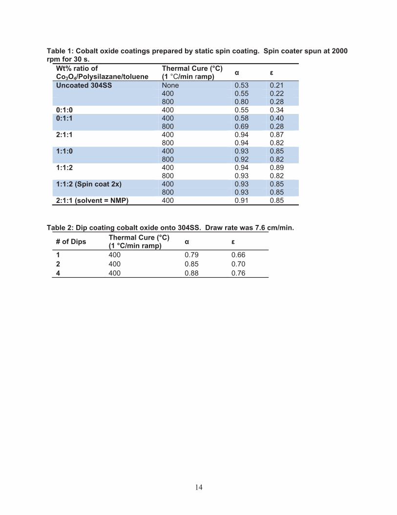
3. COBALT OXIDE 3.1 Experimental Cobalt oxide, a commercially available material and a main component in Pyromark thermal paint, was used as a model compound in an effort to measure its baseline properties, develop a film deposition method, and evaluate polysilazane as a precursor cermet base material. Coatins were prepared on 304 stainless steel (304SS) coupons using static spin coating. Coating solutions were prepared by combining cobalt oxide, Co3O4 (Alfa Aesar), Ceraset polysilazane 20 (Kion Defense Technologies) and toluene in a scintillation vial followed by ultrasonication for 15 min. The black mixture was then immediately pipetted onto a pre-cleaned 304SS coupon mounted in the spin coater. The 304SS coupon, loaded with solution, was spun at 2000 rpm for 30 s. The coated 304SS coupon was then placed in an oven and the oven ramped at 1 °C/min to 400 °C. The coupon was baked at 400 °C for 6 h and then cooled (1 °C/min) to room temperature. Some coated coupons underwent a subsequent thermal cure at 800 °C for 5 h (1°C/min ramp) to replicate concentrating solar power central receiver operating conditions. Cobalt oxide films were also prepared by dip coating. A solution of 2:1:1 Co3O4/Polysilazane/toluene was ultrasonicated for 15 min and then 304SS coupons were placed into the solution and withdrawn at a rate of 7.6 cm/min. For coating that were prepared by multiple dips, the was a 60 s rest in between dip coats. The coatings were thermally cured in the normal manner. 3.2 Results Coating the 304SS coupons with various materials had a dramatic affect on the solar absorptivity and thermal emittance values (Table 1). The coatings only with polysilazane had similar solar absorptances at thermal cures of less than 400 °C, but thermal emittance values were typically 1.5 to 2 times higher than uncoated 304SS. At the 800 °C thermal cure the polysilazane resisted increases in solar absorptivity that was observed with uncoated 304SS. This could be due to the polysilazane turning into a silicon based ceramic and/or the coating acted as a partial barrier to the oxidative processes that the uncoated 304SS underwent to at 800 °C. The addition of cobalt oxide to the coatings increased the solar absorptivity from 0.55 to over 0.9, however the thermal emittances also increased from 0.22 to over 0.8 at 400 °C. The films appeared to be of uniform thickness, although the Co3O4 was not uniformly dispersed throughout the coating. The Co3O4/polysilazane/toluene ratio appeared to have little effect on the observed solar absorptivity or thermal emittance. Thermal curing at 800 °C did not have a strong affect on solar absorptivity and thermal emittance values, however some thicker films did crack when exposed to 800 °C. As shown in Table 2, increasing the thickness of the coating by performing multiple dip coats increases the solar absorptance and thermal emittance values. It is believed as the coating thickness increases, the solar absorptance and thermal emittance values are less influenced by the 304SS substrate.
14
Table 1: Cobalt oxide coatings prepared by static spin coating. Spin coater spun at 2000 rpm for 30 s.
Wt% ratio of Co3O4/Polysilazane/toluene
Thermal Cure (°C) (1 °C/min ramp) � �
Uncoated 304SS None 0.53 0.21 400 0.55 0.22 800 0.80 0.280:1:0 400 0.55 0.34 0:1:1 400 0.58 0.40 800 0.69 0.282:1:1 400 0.94 0.87 800 0.94 0.82 1:1:0 400 0.93 0.85 800 0.92 0.821:1:2 400 0.94 0.89 800 0.93 0.82 1:1:2 (Spin coat 2x) 400 0.93 0.85 800 0.93 0.852:1:1 (solvent = NMP) 400 0.91 0.85
Table 2: Dip coating cobalt oxide onto 304SS. Draw rate was 7.6 cm/min.
# of Dips Thermal Cure (°C) (1 °C/min ramp) � �
1 400 0.79 0.66 2 400 0.85 0.70 4 400 0.88 0.76

15
4. SPINELS Spinels were chosen as promising materials because of their inherent high temperature and oxidation stability. Spinel oxides are a class of materials with the general formula ABO4. They crystallize in a cubic structure, with the oxygen anions organized in a close-packed lattice and the cations occupying some or all of the tetrahedral and octahedral sites (Figure 2). The cations can exist in a variety of oxidation states (+2, +3, +4), which allows for a variety of metal cation combinations. In addition, they are amenable to doping and substitution of a large number of transition metals, which should allow us to chemically tailor their optical properties. 4.1 Experimental Coating solutions were prepared by dissolving stoichiometric (cation) amounts of the metal nitrates and citric acid (1.5:1 molar ratio) in DI H2O and heating until a concentrated solution (approx. 0.5M) was formed. A layer of Triton-X was coated as a wetting agent (first coating only) followed by coating with the nitrate/citrate sol. Generally, 7-10 drops of solution were then deposited onto a 1 sq” stainless steel (SS304L) coupon, spun at 2000 rpm for 30 seconds. Successive layers were deposited by spin coating followed by heating the sample on a hot plate
for 2 min to dry the sol and repeating. After the ten layers were deposited, the coupon was cured for 6-12h at 600 °C (ramp rate approximately 3 °C/min). For thicker films, the entire process was repeated. Similar to the procedure in the previous chapter, polysilazane was added as a coating layer or directly to the sol in order to guage its properties as a potential cermet precursor. However, it did not have a beneficial effect on the optical properties of the film, and in some cases even resulted in cracking, delamination, or inhomogeneous coating of the spinel films. Therefore, its use was not pursued. In a set of later coatings, Triton X was added directly to the nitrate/citrate precursor solution in order to better homogenize the coating while maintaining good wetting of the SS304 surface. In this case, Triton X was added directly to the solution in a 50:1 solution:Triton X volumetric ration and stirred for several hours to assure good mixing.
Precursor solutions consisted of a 1M aqueous solution of metal nitrates to which was added Triton X (wetting agent) in a 50:1 nitrate solution:TritonX volumetric ratio and citric acid (complexing agent) in a 4:1 molar cation:citric acid ratio. This solution was stirred at room temperature for at least several hours. 7-10 drops of solution were then deposited onto a 1 sq”
Figure 2: Spinel structure. The corners ofthe polyhedral represent oxygen whilethe cations are located at the centers ofthe purple tetrahedral (A) sites and theorange octahedral (B) sites.

16
stainless steel (SS304L) coupon, spun at 2000 rpm for 30 seconds, and dried on a hot plate on medium heat. This process was repeated 10 times, and then the coupon was sintered in a box furnace at 600 °C for 6 hours (ramping rate of approximately 3°/min). The resulting coating was characterized and the entire process was repeated to form coatings of 40-50 total layers. There is little difference in the optical properties between 40 and 50 layers, so successive coatings were deemed unnecessary. In other words, a thickness was reached where the optical measurements were measuring the properties of the spinel films and not the underlying stainless steel substrate. 4.2 Results Table 3 shows a brief list of the materials studied thus far, along with their absorptance and IR emissive properties measured at room temperature. A blank coupon of SS304 was included for comparison purposes. The different compositions are differentiated by color. Differences in shading represent different deposition or heating parameters. All of the materials were deposited onto 1” stainless steel (304L) square coupons which were not pretreated in any way, except for routine cleaning, nor were any antireflective base coatings deposited before the absorber materials. 4.2.1 Formulations A variety of stoichiometric spinels, AB2O4 (A, B = Ni, Co, Fe, Cu), were synthesized in the initial screening. Powder x-ray diffraction of the products (Figure 3) indicates formation of the spinel after sintering in most cases, although the completeness of the reaction is difficult to interpret due to competing peaks from the stainless steel substrate and the low intensity, broad
20 30 40 50 60 70Two-Theta (deg)
0
500
1000
1500
2000
2500
Inte
nsity
(Cou
nts)
SS304 coupon oxidized 600CAA4-36-3: CuCo2O4 on SS304 600C/6hAA4-36-2: CuFe2O4 on SS304 600C/6h <2T(0)=0.078>AA4-36-1: CoFe2O4 on SS304 600c/6hAA4-42-3: NiFe2O4-SS, 600C/12hAA4-42-2: NiCo2O4-SS, 600C/12hAA4-42-1: FeCo2O4-SS, 600C/12h
01-073-1702> NiCo2O4 - Nickel Cobalt Oxide00-025-0283> Cuprospinel - CuFe2O4
00-003-0864> CoFe2O4 - Cobalt Iron Oxide
Figure 3: XRD of a blank SS304 coupon (black) and various formulations spin-coated and sintered (legend on left). The transparent lines correspond to identified spinel phases and are color coordinated to the legend on the left.
17
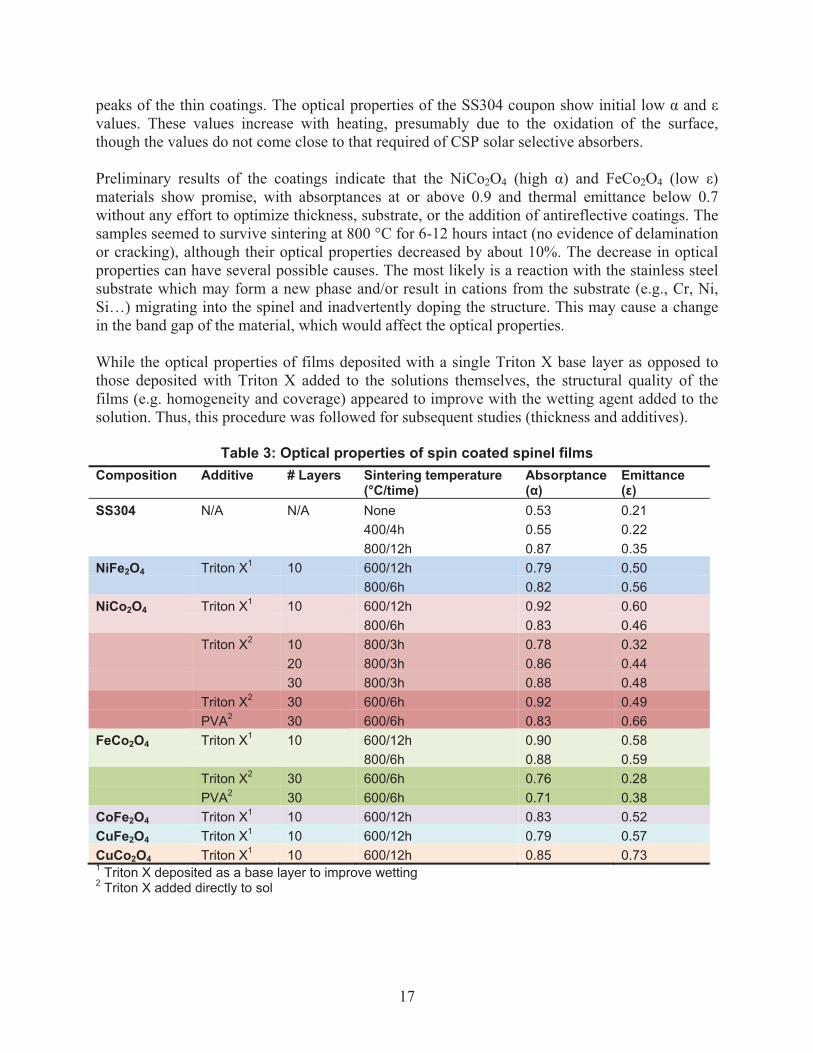
peaks of the thin coatings. The optical properties of the SS304 coupon show initial low � and � values. These values increase with heating, presumably due to the oxidation of the surface, though the values do not come close to that required of CSP solar selective absorbers. Preliminary results of the coatings indicate that the NiCo2O4 (high �) and FeCo2O4 (low �) materials show promise, with absorptances at or above 0.9 and thermal emittance below 0.7 without any effort to optimize thickness, substrate, or the addition of antireflective coatings. The samples seemed to survive sintering at 800 °C for 6-12 hours intact (no evidence of delamination or cracking), although their optical properties decreased by about 10%. The decrease in optical properties can have several possible causes. The most likely is a reaction with the stainless steel substrate which may form a new phase and/or result in cations from the substrate (e.g., Cr, Ni, Si…) migrating into the spinel and inadvertently doping the structure. This may cause a change in the band gap of the material, which would affect the optical properties. While the optical properties of films deposited with a single Triton X base layer as opposed to those deposited with Triton X added to the solutions themselves, the structural quality of the films (e.g. homogeneity and coverage) appeared to improve with the wetting agent added to the solution. Thus, this procedure was followed for subsequent studies (thickness and additives).
Table 3: Optical properties of spin coated spinel films
1 Triton X deposited as a base layer to improve wetting 2 Triton X added directly to sol
Composition Additive # Layers Sintering temperature (°C/time)
Absorptance (�)
Emittance (�)
SS304 N/A N/A None 0.53 0.21 400/4h 0.55 0.22 800/12h 0.87 0.35 NiFe2O4
Triton X1 10 600/12h 0.79 0.50 800/6h 0.82 0.56 NiCo2O4 Triton X1 10 600/12h 0.92 0.60 800/6h 0.83 0.46 Triton X2 10 800/3h 0.78 0.32 20 800/3h 0.86 0.44 30 800/3h 0.88 0.48 Triton X2 30 600/6h 0.92 0.49 PVA2 30 600/6h 0.83 0.66 FeCo2O4 Triton X1 10 600/12h 0.90 0.58 800/6h 0.88 0.59 Triton X2 30 600/6h 0.76 0.28 PVA2 30 600/6h 0.71 0.38 CoFe2O4 Triton X1 10 600/12h 0.83 0.52 CuFe2O4 Triton X1 10 600/12h 0.79 0.57 CuCo2O4 Triton X1 10 600/12h 0.85 0.73
18
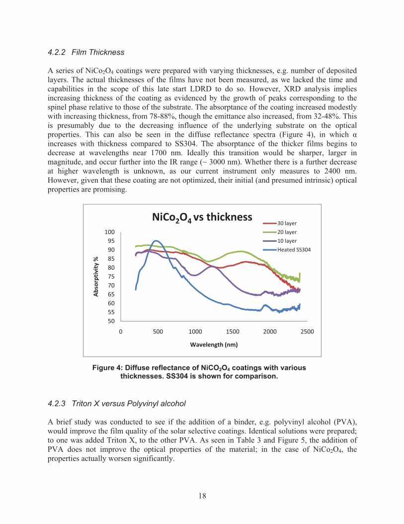
4.2.2 Film Thickness A series of NiCo2O4 coatings were prepared with varying thicknesses, e.g. number of deposited layers. The actual thicknesses of the films have not been measured, as we lacked the time and capabilities in the scope of this late start LDRD to do so. However, XRD analysis implies increasing thickness of the coating as evidenced by the growth of peaks corresponding to the spinel phase relative to those of the substrate. The absorptance of the coating increased modestly with increasing thickness, from 78-88%, though the emittance also increased, from 32-48%. This is presumably due to the decreasing influence of the underlying substrate on the optical properties. This can also be seen in the diffuse reflectance spectra (Figure 4), in which � increases with thickness compared to SS304. The absorptance of the thicker films begins to decrease at wavelengths near 1700 nm. Ideally this transition would be sharper, larger in magnitude, and occur further into the IR range (~ 3000 nm). Whether there is a further decrease at higher wavelength is unknown, as our current instrument only measures to 2400 nm. However, given that these coating are not optimized, their initial (and presumed intrinsic) optical properties are promising.
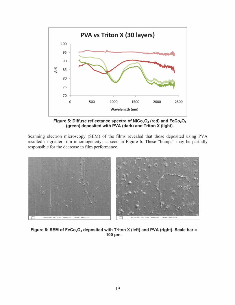
4.2.3 Triton X versus Polyvinyl alcohol A brief study was conducted to see if the addition of a binder, e.g. polyvinyl alcohol (PVA), would improve the film quality of the solar selective coatings. Identical solutions were prepared; to one was added Triton X, to the other PVA. As seen in Table 3 and Figure 5, the addition of PVA does not improve the optical properties of the material; in the case of NiCo2O4, the properties actually worsen significantly.
50556065707580859095
100
0 500 1000 1500 2000 2500
Absorptiv
ity�%
Wavelength�(nm)
NiCo2O4�vs�thickness� 30�layer20�layer10�layerHeated�SS304
Figure 4: Diffuse reflectance of NiCO2O4 coatings with various thicknesses. SS304 is shown for comparison.
19
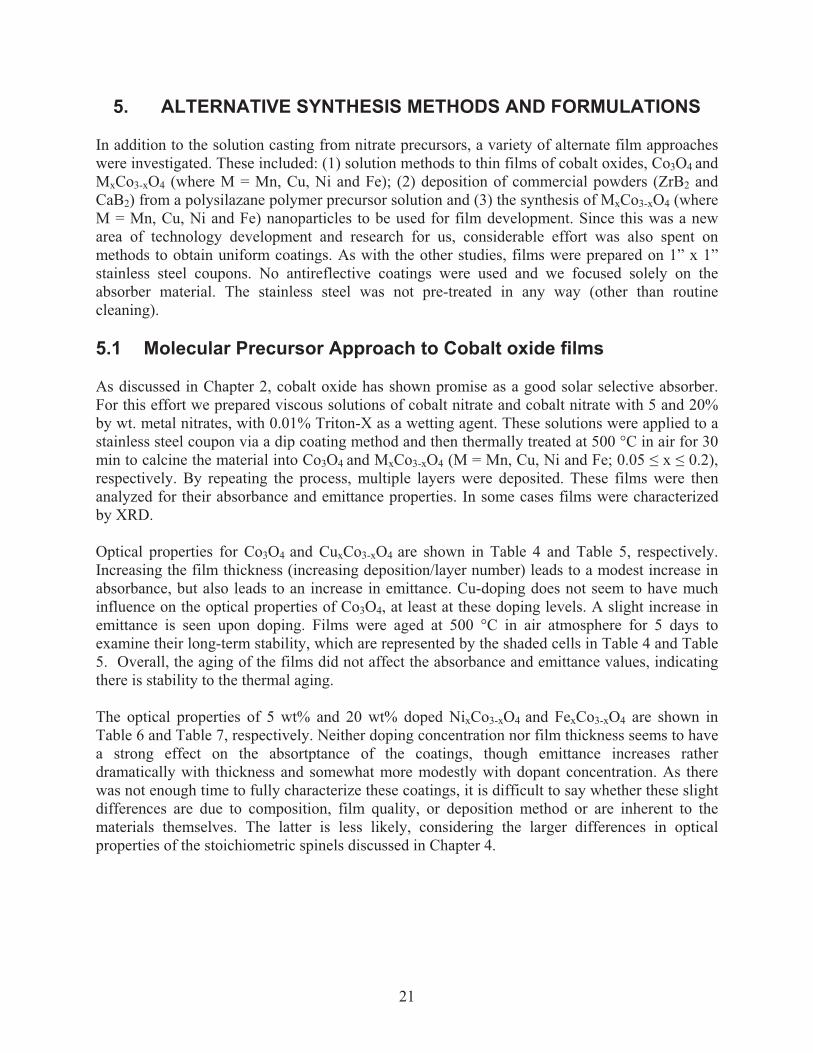
Scanning electron microscopy (SEM) of the films revealed that those deposited using PVA resulted in greater film inhomogeneity, as seen in Figure 6. These “bumps” may be partially responsible for the decrease in film performance.
70
75
80
85
90
95
100
0 500 1000 1500 2000 2500
A�%
Wavelength�(nm)
PVA�vs�Triton�X�(30�layers)
Figure 5: Diffuse reflectance spectra of NiCo2O4 (red) and FeCo2O4 (green) deposited with PVA (dark) and Triton X (light).
Figure 6: SEM of FeCo2O4 deposited with Triton X (left) and PVA (right). Scale bar = 100 �m.

20
21
5. ALTERNATIVE SYNTHESIS METHODS AND FORMULATIONS In addition to the solution casting from nitrate precursors, a variety of alternate film approaches were investigated. These included: (1) solution methods to thin films of cobalt oxides, Co3O4 and MxCo3-xO4 (where M = Mn, Cu, Ni and Fe); (2) deposition of commercial powders (ZrB2 and CaB2) from a polysilazane polymer precursor solution and (3) the synthesis of MxCo3-xO4 (where M = Mn, Cu, Ni and Fe) nanoparticles to be used for film development. Since this was a new area of technology development and research for us, considerable effort was also spent on methods to obtain uniform coatings. As with the other studies, films were prepared on 1” x 1” stainless steel coupons. No antireflective coatings were used and we focused solely on the absorber material. The stainless steel was not pre-treated in any way (other than routine cleaning). 5.1 Molecular Precursor Approach to Cobalt oxide films As discussed in Chapter 2, cobalt oxide has shown promise as a good solar selective absorber. For this effort we prepared viscous solutions of cobalt nitrate and cobalt nitrate with 5 and 20% by wt. metal nitrates, with 0.01% Triton-X as a wetting agent. These solutions were applied to a stainless steel coupon via a dip coating method and then thermally treated at 500 °C in air for 30 min to calcine the material into Co3O4 and MxCo3-xO4 (M = Mn, Cu, Ni and Fe; 0.05 � x � 0.2), respectively. By repeating the process, multiple layers were deposited. These films were then analyzed for their absorbance and emittance properties. In some cases films were characterized by XRD. Optical properties for Co3O4 and CuxCo3-xO4 are shown in Table 4 and Table 5, respectively. Increasing the film thickness (increasing deposition/layer number) leads to a modest increase in absorbance, but also leads to an increase in emittance. Cu-doping does not seem to have much influence on the optical properties of Co3O4, at least at these doping levels. A slight increase in emittance is seen upon doping. Films were aged at 500 °C in air atmosphere for 5 days to examine their long-term stability, which are represented by the shaded cells in Table 4 and Table 5. Overall, the aging of the films did not affect the absorbance and emittance values, indicating there is stability to the thermal aging. The optical properties of 5 wt% and 20 wt% doped NixCo3-xO4 and FexCo3-xO4 are shown in Table 6 and Table 7, respectively. Neither doping concentration nor film thickness seems to have a strong effect on the absortptance of the coatings, though emittance increases rather dramatically with thickness and somewhat more modestly with dopant concentration. As there was not enough time to fully characterize these coatings, it is difficult to say whether these slight differences are due to composition, film quality, or deposition method or are inherent to the materials themselves. The latter is less likely, considering the larger differences in optical properties of the stoichiometric spinels discussed in Chapter 4.

22
Table 4: Optical properties of cobalt oxide films prepared by dip coating.
Sample Number of Coatings
Absorbance �
Thermal Emittance �
TL96-1A 1 0.854 0.200 TL96-1B 1 0.836 0.202 TL45-1a 1 0.859 0.269TL96-3A 3 0.825 0.320 TL96-3B 3 0.864 0.318 TL45-3a 3 0.860 0.331TL96-4A 4 0.860 0.357 TL96-4B 4 0.882 0.344 TL45-4b 4 0.860 0.368TL96-6A 6 0.849 0.444 TL96-6B 6 0.853 0.458 TTL45-6a 6 0.847 0.431TL96-8A 8 0.860 0.502
a Films were aged at 500 °C in air for 4 days.
Table 5: Optical properties of copper-doped (5 wt%) cobalt oxide films prepared by dip coating.
Sample Number of Coatings
Absorbance �
Thermal Emittance �
Oxidized SS304 NA 0.480 0.297 MB166-1A 1 0.814 0.365 MB166-1B 1 0.868 0.360 MB166-1HFa 1 0.856 0.290 MB166-1b 1 0.835 0.351MB 166-3A 3 0.890 0.414 MB166-3B 3 0.884 0.790 MB166-3b 3 0.875 0.542MB166-6A 6 0.876 0.770 MB66-6B 6 0.889 0.675 MB166-6b 6 0.870 0.717
aThis sample was heated immediately after dip coating and provided a smoother film as determined visually.b Films were aged at 500 °C in air for 4 days. Composite films with anti-reflective (AR) coatings will be required to lower the emittance values for these films. Coating the stainless steel with various materials (i.e. nickel or iron) is another approach that can be used to lower the thermal emittance. Several of these films were also aged at 500 °C in air atmosphere for 5 days to examine their long-term stability. Absorbance and emittance values were essentially the same before and after aging (not shown), indicating that the films exhibit good stability to the thermal aging at 500 °C.

23
Table 6: Optical properties of nickel-doped (5, 20 wt%) cobalt oxide films prepared by dip coating.
Sample Wt % Ni Number of Coatings
Absorbance �
Emittance �
MB25-A 5 1 0.86 0.26 MB25-B 5 1 0.87 0.47 MB26-A 20 1 0.88 0.35MB26-B 20 1 0.86 0.37MB25-C 5 3 0.89 0.83 MB25-D 5 3 0.91 0.62 MB26-C 20 3 0.90 0.76MB26-D 20 3 0.90 0.89MB25-E 5 6 0.86 0.83 MB25-F 5 6 0.90 0.71 MB26-E 20 6 0.88 0.87MB26-F 20 6 0.89 0.87
Table 7: Optical properties of iron-doped (5, 20 wt%) cobalt oxide films prepared by dip coating.
Sample Wt % Fe Number of Coatings Absorbance Thermal Emittance
MB32-A 5 1 0.83 0.15 MB32-B 5 1 0.84 0.16 MB33-A 20 1 0.84 0.35MB33-B 20 1 0.87 0.27MB32-C 5 3 0.88 0.31 MB32-D 5 3 0.89 0.30 MB33-C 20 3 0.87 0.35MB33-D 20 3 0.86 0.47MB32-E 5 6 0.85 0.46 MB32-F 5 6 0.87 0.40 MB32-G 5 6 0.86 0.61 MB33-E 20 6 0.88 0.71MB33-F 20 6 0.89 0.81
5.2 Poly(silazane) : ZrB2 films Commercial powders of zinc boride (ZrB2) were suspended with polysilazane (in toluene) solution with sonication and then applied to a stainless steel coupon via spin coating. The films were thermally treated at 500 °C in air for 30 min in order to form ZrB2/SixOyNz composite coatings. ZrB2 is known to be a solar selective material; however, it is susceptible to oxidation in air and also requires AR coatings to be effective. It was our intention that the SixOyNz component

24
could act as a protective coating. In general the boride powders did not disperse well in toluene, which caused problems with controlling film thickness and uniformity. The absorbance and emittance for the ZrB2 films were found to be independent of the number of layers deposited, as seen in Table 8. Aging these films at 500 °C in air lead to a slight increase in absorbance (Table 8, shaded); however, the emittance values increased drastically, likely due to oxidation of the ZrB2. Firing these films under argon should provide for a ZrB2/Si3N4 composite with increased air stability. Multi-coating techniques are also of interest. Due to time and funding constraints, new routes to make ZrB2 from molecular precursors were not examined.
Table 8: Optical properties of ZrB2:Polysilazane films prepared by spin coating.
Sample Number of Coatings Absorbance Thermal Emittance
TT-1 1 0.80 0.36 TT-2 1 0.80 0.36 TT-3 1 0.82 0.35 TT-4 1 0.80 0.36 TT-5 1 0.80 0.35 TT-6 1 0.80 0.35 TT-7 1 0.79 0.34 TT-8 1 0.77 0.44
ZrB2-Ca 1 0.82 0.67ZrB2-Aa 1 0.82 0.57
5.3 MxCo3-xO4 Nanoparticles Due to the poor solubility of the ZrB2 and commercial cobalt oxide powders in the polysilazane (toluene) solution, it was decided that creating soluble versions of these powders might be a feasible approach to increase control of film preparation. Hence, the synthesis of MxCo3-xO4 nanoparticles (M = Ni, Cu, Mn and Fe) was undertaken. There are few low temperature and cost effective solution routes to these materials available in the literature. Hence, our approach here was to utilize the decomposition of metal nitrate precursors in a solution of 1-hexanol at 140 °C. We have shown that the synthesis of toluene-soluble Co3O4 is indeed feasible and can be prepared readily on a large scale, with good purity, as seen in the XRD pattern of the product (Figure 7) To date we have prepared up to 5 grams batches with ~ 70-80 % yield using this solution approach. Kilogram scale synthesis seems entirely likely given the ease of the synthetic preparation. This method produces ~50 nm diameter spinel Co3O4 nanoclusters/nanoparticles that are mesoporous and comprised of smaller nanoparticles (~5 nm in diameter) that are crystallographically aligned (Figure 8).

25
We extended this work further by examining metal substitution into the spinel structure to create MxCo3-xO4 nanoparticles, where x = 0.2, 0.5, 1, 1.5, and 2 and M = Ni, Cu, Mn and Fe, in order to tailor the solar selective nature of films. Mn (Figure 9) and Fe appear to substitute into Co3O4 in all cases, x = 0.2-2.0, though at higher Fe-loadings the XRD is difficult to interpret due to very weak peaks. This may be due to either very small particle size and/or decreasing crystallinity of the material. Nickel was only soluble at x = 0.2 under these conditions; attempts at increased doing resulted in the presence of excess Ni(NO)2 observed by XRD. Copper did not substitute into the spinel at all. Only products that appeared single-phase were analyzed further and used for film formation.
Figure 7: Powder x-ray diffraction pattern of isolated Co3O4 nanoparticles prepared from Co(NO3)2 in 1-hexanol at 140 °C.
Figure 8: Transmission Electron microscopy (TEM) images of Co3O4 nanoparticles.

26
It is interesting to note that the morphology of the nanoparticles changes with increased substitution. The particles ranged from ~50 nm mesoporous clusters (x < 0.5) to individual smaller (2-5 nm) nanoparticles (x > 1), as seen in Figure 10 for the Mn series. Thermogravimetric analysis (TGA) revealed that the particles consisted of ~10 % by weight of ligand (hexanol). In order to synthesize coatings, Co3O4 nanoparticles were dissolved in toluene, spin coated onto SS304 coupons and heat treated. In general, the nanoparticle-based films were more homogenous than those made from commercial powders, even when polysilazane was added to the solution, though the presence of polysilazane did not result in improved properties. The optical properties were promising, as seen in Table 9.
Figure 9: XRD of MnxCo3-xO4 (x = 0.2 – 2.0) nanoparticles. Broadening is consistent with smaller particle sized observed in TEM.
Figure 10: TEM micrographs of isolated MnxCo3-xO4 nanoparticles prepared from Co(NO3)2 and Mn(NO3)2 in 1-hexanol at 140 °C.
27
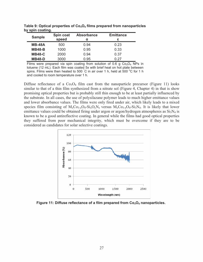
Table 9: Optical properties of Co3O4 films prepared from nanoparticles by spin coating.
Sample Spin coat speed
Absorbance �
Emittance �
MB-48A 500 0.94 0.23 MB48-B 1000 0.95 0.33 MB48-C 2000 0.94 0.37 MB48-D 3000 0.95 0.27
Films were prepared via spin coating from solution of 0.6 g Co3O4 NPs in toluene (12 mL). Each film was coated 5x with brief heat on hot plate between spins. Films were then heated to 500 °C in air over 1 h, held at 500 oC for 1 h and cooled to room temperature over 1 h.
Diffuse reflectance of a Co3O4 film cast from the nanoparticle precursor (Figure 11) looks similar to that of a thin film synthesized from a nitrate sol (Figure 4, Chapter 4) in that is show promising optical properties but is probably still thin enough to be at least partially influenced by the substrate. In all cases, the use of polysilazane polymer leads to much higher emittance values and lower absorbance values. The films were only fired under air, which likely leads to a mixed species film consisting of MxCo3-xO4-SixOyNz versus MxCo3-xO4-Si3N4. It is likely that lower emittance values could be obtained firing under argon or argon/hydrogen atmospheres as Si3N4 is known to be a good antireflective coating. In general while the films had good optical properties they suffered from poor mechanical integrity, which must be overcome if they are to be considered as candidates for solar selective coatings.
Figure 11: Diffuse reflectance of a film prepared from Co3O4 nanoparticles.

28

29
6. THERMAL SPRAY COATINGS FOR APPLICATION AS SOLAR SELECTIVE COATINGS
6.1 Solar Coating Requirements Solar selective coatings require high solar absorbance and low thermal emission at temperatures exceeding 600 °C [1]. Such a coating conformally applied to tube sheet could significantly improve the performance of solar concentrators. Because of the high heat flux associated with solar concentrators, coating durability will be a challenge. Any coating used on a solar concentrator must be able to survive in a high heat environment (> 600 ºC) and be air-stable. In addition, the ability to apply or repair the coating in the field is desirable. The tube sheets of solar concentrators are large and costly to relocate.
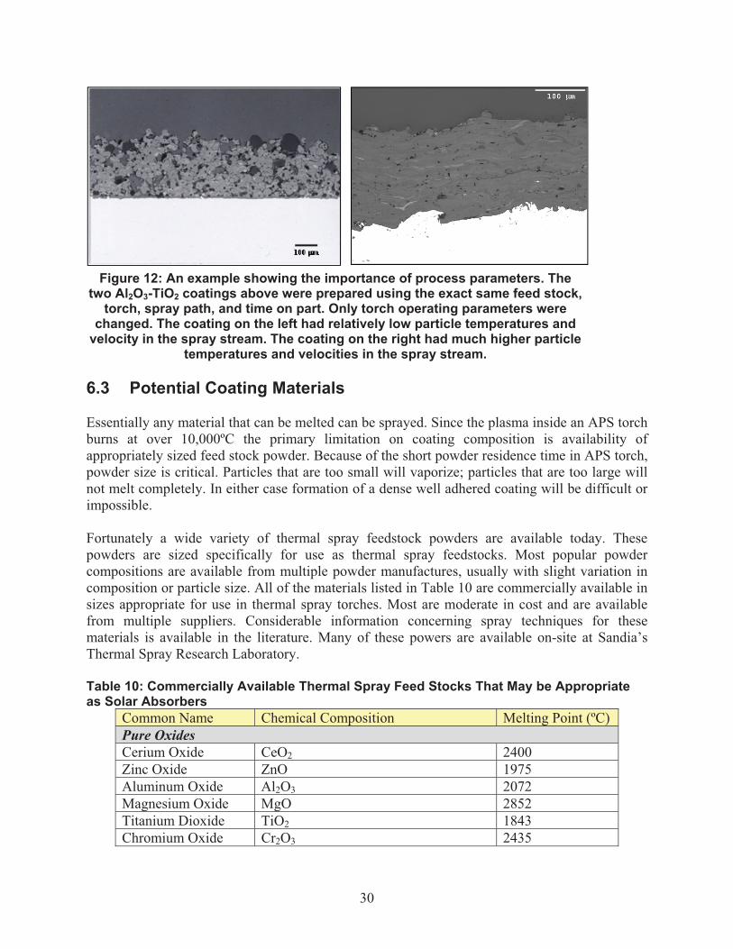
6.2 Thermal Spray Coatings Thermal spray coating processes are flexible tools for preparing metal and ceramic coatings. Like welding processes, many different types of thermal spray processes exist. They are differentiated by energy source (flame, arc, plasma, etc…) and/or feed stock form (powder or wire). Many thermal spray processes are extremely portable and routinely used to apply coatings in the field. Large objects like bridges, rolling mill rolls, and paper mill rolls are routinely coated in place. Solar collector coatings would most likely be applied using an air-plasma-spray process because of the high melting points of the materials involved and the need to spray in the field. Air-plasma-spray (APS) is an extremely common spray process. An arc plasma, generated inside the torch, melts the feedstock powder and propels it downstream. When the feedstock droplets encounter the substrate they deform and solidify to form a coating. All of the materials listed in Table 10 can be melted and sprayed using an appropriately configured APS torch. Process parameters can significantly affect coating microstructures and properties, Figure 12. This allows coating properties like adhesion strength, roughness, porosity, strain tolerance, etc… to be tuned for specific applications.
30
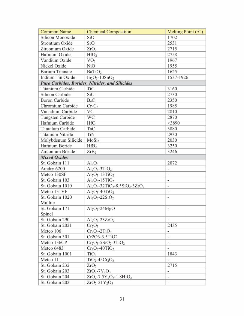
6.3 Potential Coating Materials Essentially any material that can be melted can be sprayed. Since the plasma inside an APS torch burns at over 10,000ºC the primary limitation on coating composition is availability of appropriately sized feed stock powder. Because of the short powder residence time in APS torch, powder size is critical. Particles that are too small will vaporize; particles that are too large will not melt completely. In either case formation of a dense well adhered coating will be difficult or impossible. Fortunately a wide variety of thermal spray feedstock powders are available today. These powders are sized specifically for use as thermal spray feedstocks. Most popular powder compositions are available from multiple powder manufactures, usually with slight variation in composition or particle size. All of the materials listed in Table 10 are commercially available in sizes appropriate for use in thermal spray torches. Most are moderate in cost and are available from multiple suppliers. Considerable information concerning spray techniques for these materials is available in the literature. Many of these powers are available on-site at Sandia’s Thermal Spray Research Laboratory. Table 10: Commercially Available Thermal Spray Feed Stocks That May be Appropriate as Solar Absorbers
Common Name Chemical Composition Melting Point (ºC) Pure Oxides Cerium Oxide CeO2 2400 Zinc Oxide ZnO 1975 Aluminum Oxide Al2O3 2072 Magnesium Oxide MgO 2852 Titanium Dioxide TiO2 1843 Chromium Oxide Cr2O3 2435
Figure 12: An example showing the importance of process parameters. The two Al2O3-TiO2 coatings above were prepared using the exact same feed stock,
torch, spray path, and time on part. Only torch operating parameters were changed. The coating on the left had relatively low particle temperatures and
velocity in the spray stream. The coating on the right had much higher particle temperatures and velocities in the spray stream.
31
Common Name Chemical Composition Melting Point (ºC) Silicon Monoxide SiO 1702 Strontium Oxide SrO 2531 Zirconium Oxide ZrO2 2715 Hafnium Oxide HfO2 2758 Vandium Oxide VO2 1967 Nickel Oxide NiO 1955 Barium Titanate BaTiO2 1625 Indium Tin Oxide In2O3-10SnO2 1537-1926 Pure Carbides, Borides, Nitrides, and Silicides Titanium Carbide TiC 3160 Silicon Carbide SiC 2730 Boron Carbide B4C 2350 Chromium Carbide Cr3C2 1985 Vanadium Carbide VC 2810 Tungsten Carbide WC 2870 Hafnium Carbide HfC >3890 Tantalum Carbide TaC 3880 Titanium Nitride TiN 2930 Molybdenum Silicide MoSi2 2030 Hafnium Boride HfB2 3250 Zirconium Boride ZrB2 3246 Mixed Oxides St. Gobain 111 Al2O3 2072 Amdry 6200 Al2O3-3TiO2 - Metco 130SF Al2O3-13TiO2 - St. Gobain 103 Al2O3-15TiO2 - St. Gobain 1010 Al2O3-32TiO2-8.5SiO2-3ZrO2 - Metco 131VF Al2O3-40TiO2 - St. Gobain 1020 Mullite
Al2O3-22SiO2 -
St. Gobain 171 Spinel
Al2O3-24MgO -
St. Gobain 290 Al2O3-23ZrO2 - St. Gobain 2021 Cr2O3 2435 Metco 106 Cr2O3-2TiO2 - St. Gobain 301 Cr2O3-3.5TiO2 - Metco 136CP Cr2O3-5SiO2-3TiO2 - Metco 6483 Cr2O3-40TiO2 - St. Gobain 1001 TiO2 1843 Metco 111 TiO2-45Cr2O3 - St. Gobain 232 ZrO2 2715 St. Gobain 203 ZrO2-7Y2O3 - St. Gobain 204 ZrO2-7.5Y2O3-1.8HfO2 - St. Gobain 202 ZrO2-21Y2O3 -
32
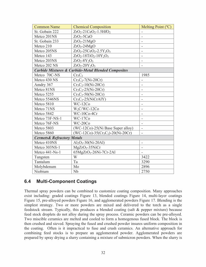
Common Name Chemical Composition Melting Point (ºC) St. Gobain 222 ZrO2-21CeO2-1.5HfO2 - Metco 201NS ZrO2-5CaO - St. Gobain 233 ZrO2-21MgO - Metco 210 ZrO2-24MgO - Metco 205NS ZrO2-25CeO2-2.5Y2O3 - Metco 143 ZrO2-18TiO2-10Y2O3 - Metco 203NS ZrO2-8Y2O3 - Metco 202 NS ZrO2-20Y2O3 - Carbide Mixtures & Carbide-Metal Blended Composites Metco 70C-NS Cr3C2 1985 Metco 430 NS Cr3C2-7(Ni-20Cr) - Amdry 367 Cr3C2-10(Ni-20Cr) - Metco 81NS Cr3C2-25(Ni-20Cr) - Metco 5255 Cr3C2-50(Ni-20Cr) - Metco 5546NS Cr3C2-25(NiCrAlY) - Metco 5810 WC-12Co - Metco 71NS W2C/WC-12Co - Metco 5842 WC-10Co-4Cr - Metco 73F-NS-1 WC-17Co - Metco 76F-NS WC-20Co - Metco 5803 (WC-12Co)-25(Ni Base Super alloy) - Metco 5860 (WC-12Co)-35(Cr3C2)-20(Ni-20Cr) - Cermets& Refractory Metals Metco 410NS Al2O3-30(Ni-20Al) - Metco 303NS-1 MgZrO3-35NiCr - Metco 441-Ns-1 65MgZrO3-26Ni-7Cr-2Al - Tungsten W 3422 Tantalum Ta 3290 Molybdenum Mo 2896 Niobium Nb 2750
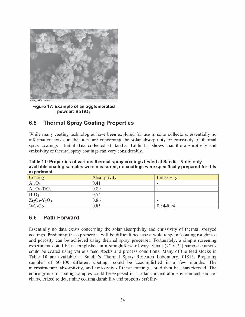
6.4 Multi-Component Coatings Thermal spray powders can be combined to customize coating composition. Many approaches exist including: graded coatings Figure 13, blended coatings Figure 14, multi-layer coatings Figure 15, pre-alloyed powders Figure 16, and agglomerated powders Figure 17. Blending is the simplest strategy. Two or more powders are mixed and delivered to the torch as a single feedstock stream. Typically, this produces a blended coating (salt & pepper mixture) because feed stock droplets do not alloy during the spray process. Ceramic powders can be pre-alloyed. Two miscible ceramics are melted and cooled to form a homogenous fused block. The block is then crushed and sieved. Spraying the fused and crushed powder insures uniform composition in the coating. Often is it impractical to fuse and crush ceramics. An alternative approach for combining feed stocks is to prepare an agglomerated powder. Agglomerated powders are prepared by spray drying a slurry containing a mixture of submicron powders. When the slurry is

33
spray dried, the submicron powders group together to form larger agglomerated particles. The agglomerate composition is controlled by the composition of the slurry. While agglomerated powders are not pre-alloyed, they will alloy during the spray process. A more complex approach is to deliver two or more independent feedstock streams to the spray torch. By varying the powder feed rate for each stream graded coatings and multi-layer coatings can be readily prepared.
Figure 13: Example of a copper-aluminum graded coating.
Figure 14: Example of an aluminum-polyester blended coating
Figure 15: Example of a copper-tungsten multi-layer coating Figure 16: Example of a fused and
crushed powder: Al2O3-TiO2
34
6.5 Thermal Spray Coating Properties While many coating technologies have been explored for use in solar collectors; essentially no information exists in the literature concerning the solar absorptivity or emissivity of thermal spray coatings. Initial data collected at Sandia, Table 11, shows that the absorptivity and emissivity of thermal spray coatings can vary considerably. Table 11: Properties of various thermal spray coatings tested at Sandia. Note: only available coating samples were measured, no coatings were specifically prepared for this experiment. Coating Absorptivity Emissivity Al2O3 0.41 - Al2O3-TiO2 0.89 - HfO2 0.54 - Zr2O3-Y2O3 0.86 - WC-Co 0.85 0.84-0.94 6.6 Path Forward Essentially no data exists concerning the solar absorptivity and emissivity of thermal sprayed coatings. Predicting these properties will be difficult because a wide range of coating roughness and porosity can be achieved using thermal spray processes. Fortunately, a simple screening experiment could be accomplished in a straightforward way. Small (2” x 2”) sample coupons could be coated using various feed stocks and process conditions. Many of the feed stocks in Table 10 are available at Sandia’s Thermal Spray Research Laboratory, 01813. Preparing samples of 50-100 different coatings could be accomplished in a few months. The microstructure, absorptivity, and emissivity of these coatings could then be characterized. The entire group of coating samples could be exposed in a solar concentrator environment and re-characterized to determine coating durability and property stability.
Figure 17: Example of an agglomerated powder: BaTiO2

35
Once completed, this experiment would provide a large amount of data concerning the suitability of thermal spray coatings for application in solar concentrators. Given the wide range of ceramics, carbides, borides, and cermets that can be sprayed and the control coating microstructure offered by thermal spray processes, it is likely that a pathway to an improved solar selective coating can be identified.

36

37
7. CONCLUSIONS . Concentrating solar power (CSP) systems use solar absorbers to convert sunlight to electric power. Increased operating temperatures of the central receiver CSP process are necessary to lower the cost of the solar generated electricity by improving power cycle efficiencies and reducing thermal energy storage costs. In order for CSP to meet an electricity cost target of $0.055/kWh, durable new materials are needed to cope with operating temperatures >600 °C. Ideal absorbers have high solar absorptance (>0.95) in the visible region and low thermal emittance (<0.05) in the IR region, be stable in air, and be low-cost and readily manufacturable. In the case of central receivers, little effort has been spent in this area; the bulk of research has been in the field of trough receivers, which generally operate in vacuum and require smaller coated surface areas. The current coating technology for central receivers, Pyromark High Temperature paint, has a solar absorptance in excess of 0.95 but a thermal emittance greater than 0.8, which results in large thermal losses at high temperatures. In addition, because solar receivers operate in air, these coatings have long term stability issues that add to the operating costs of CSP facilities. In the course of this late start LDRD, we have begun to develop film deposition methods onto stainless steel (SS304L) coupons using spin coating and dip coating techniques. In addition, we screened both commercially available materials (polysilazane, Co3O4) and lab-synthesized materials for their optical and structural properties. Spinel oxides were chosen for their inherent high temperature and oxidation stability and their amenability to doping and substitution of a large number of transition metal cations, which should allow us to chemically tailor their properties. Durability tests have also been initiated with some preliminary success, in that the spinel coatings are stable in air at temperatures up to 600 °C, though they do begin to suffer from optical degradation at 800 °C. The oxide spinel materials continue to show promise as intrinsic solar-selective absorptant materials. They display relatively high absorptivity and stability at high temperatures and in air. Their emittance values are still higher than preferred, but doping and cation-substitution strategies may still lead to lower values. This late start has resulted in follow-on funding from the Advanced Concepts task of the Solar AOP at Sandia (funded by DOE). As this is still a relatively new project, there are still many avenues in materials formulations to be explored, including the use of nanoparticle precursors. Another potential work-around would be the addition of anti-reflective coatings or base-layers. These will be explored in the coming year. In addition, longer-term (e.g., over multiple temperature cycles) durability tests will be designed and executed. More in-depth structural characterization should be employed in order to better understand any potential interaction between the substrate and coating at high temperature and its effects on the optical properties of the materials. Finally, collaboration with the thermal spray group will continue as we explore doping strategies of thermal-sprayed films. .

38

39
8. REFERENCES 1. J.A. Stokes, J.C. Jafolla, Solar Selective Pigmented Coatings, Report # SOC-R1072-001-
0298, Sandia National Laboratories, Feb. 1998

40
41
DISTRIBUTION 1 Andrea Ambrosini 6364 1 Ellen Stechel 6364 1 Chad Staiger 6364 1 Marlene Bencomo 6364 1 Timothy Lambert 6364 1 Aaron Hall 1831 1 Nathan Siegel 6363 1 Clifford Ho 6363 1 MS0899 Technical Library 9536 (electronic copy) 1 MS0359 D. Chavez, LDRD Office 1911

42