Improved double zepp - Antennas By N6LF
3
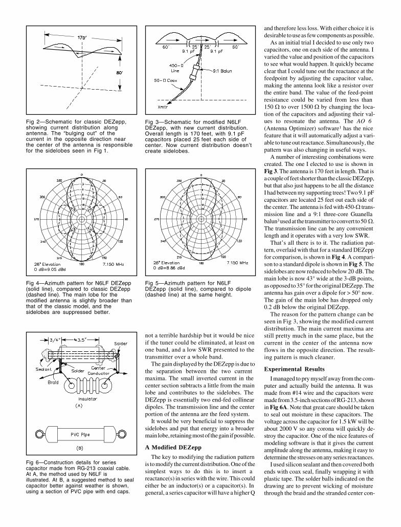
N6LF revisits the classic double extended Zepp to improve pattern and SWR bandwidth. He also offers some sage advice about computer modeling. An Improved Double Extended Zepp By Rudy Severns, N6LF 32857 Fox Lane PO Box 589 Cottage Grove, OR 97424 T he sunspot cycle is headed down and the low bands are coming to life for DXing. The next several years will be the time to make those low-band contacts for DXCC. As always, the key to low-band operation is a good antenna. Unfortunately for 7 MHz and down, good antennas don’t come in a box ready to assemble. Every lo- cation will have a unique set of limitations and opportunities. One very important difference between this sunspot minima and all past ones is the avail- ability of inexpensive, easy-to-use and pow- erful antenna modeling software. 1,2 This soft- ware allows you to design and optimize an antenna that exactly fits your situation and pocketbook. While cut-and-try experimenta- tion is a very slow way to optimize antennas, modeling is so quick that a wide range of so- lutions can be investigated easily. The real problem with modeling is generating the will power to stop fooling with the variations and go out and build something! The following article uses 40 and 80/75- meter double extended Zepps (DEZepp) as examples of what you can accomplish. By adding two small capacitors, made from short lengths of RG-8, in just the right place, the pattern can be improved and the driving- point impedance changed from reactive and narrowband to resistive and wideband. This allows the antenna to be used without a tuner and with an SWR < 1.5:1 over the entire 40- meter band, or with SWR < 2:1 over the entire 75/80-meter band. A Look at the Classical DEZepp The classical DEZepp is simply a piece of wire 1.25 λ long, fed at the center, usually with open-wire transmission line and a tuner at the transmitter. The DEZepp displays a useful amount of gain over a dipole of approximately 3 dB. The radiation pattern for a DEZepp de- signed for 7.15 MHz and suspended 80 feet above ground is shown in Fig 1, along with the pattern for a λ/2 dipole at the same height for comparison. The elevation angle is 26°, the peak of the main lobe. The current distribu- tion along the antenna is shown in Fig 2. The DEZepp does indeed provide gain over the dipole, but only over the relatively small angle of approximately 40°. The beamwidth between 3 dB points is 35°. Unless the antenna is pointed directly toward the receiving sta- tion, the gain is not usable due to the narrow beam width. In addition to the narrow main lobe, there are significant sidelobes. These are not big enough to be helpful in those direc- tions, but they will also certainly pick up noise and interference. The impedance of the an- tenna is very reactive, and even when matched at midband does not allow the entire band to be covered without retuning. For this reason, the DEZepp has tradition- ally been used with an antenna tuner. This is Fig 1—Azimuth pattern of classic double extended Zepp (solid line) at 7.15 MHz, compared with standard dipole (dashed line), both 80 feet high over average ground. Patterns are shown at 26° elevation, where the gain is maximum. The wire runs along the 270° to 90° axis on the graph. Note significant sidelobes for DEZepp.
Transcript of Improved double zepp - Antennas By N6LF