
Improved Design and Analysis of the F lexible Scr ew ...
8
1. Introduction Earthworms drive body movement by alternately expanding and contracting different cylindrical segments of the body [1]. Inspired by earthworm, Worm robot [2,3], which has a worm peristaltic locomotion mechanism, is particularly suitable for movement in a soft, curved environment by reason of its simple structure, low energy consumption, and large driving force.Worm robots are better at accomplishing tasks in some environments, such as pipe inspection in industry. and endoscopic fields in medical rehabilitation. There are many methods for achieving worm peristaltic locomotion, motor [4,5], shape-memory alloy actuators[6], magnetic fluid [7,8], pneumatic actuators[9] and electroactive polymer[10] are all used by researchers to develop worm robots. Among all the driving actuators, motors are a common method to produce peristaltic locomotion. The number of motors used in robots varies from one to many. Fang[11] proposed eight-segment earthworm-like in-pipe robot which use active servomotors and spring-steel belts to pass horizontal and vertical pipes. However, its control system and the structure are complicated. Kakogawa [12] proposed a screw drive mechanism using one motor as rotator and other two units as a stator with wheel driving for worm robot. It can performs high mobility in both straight pipes and curved pipes, however, as the motion of the robot is close to the pipe and rotate to spiral motion. The feed motion of the robot will be slow when it work in large diameter of the pipe. In order to increase the feeding velocity, simplify the structure of the mechanism, and adapt to the environment, in our previous work, a flexible screw mechanism (FSM) [13] was designed, consists of Rectangular helical compression spring and nut with rollers. Inside the nut fixed rollers rotate around the spring of the FSM to transmit the force. The robot with this mechanism is tested and can adapt its shape to the environment as it bend large deflection and return its original deformation. However, during the feeding motion of the flexible shaft, the large deflection result in more bending energy than feeding energy, and the transmission is decreased. In this paper, we analyzed and tested the improved design of the shaft compared with the single spring shaft. First, in order to get analytical model of the shaft, the lateral deflection of the equivalent beam is formulated by the exact differential equation. Second, the difference of the lateral deflection under the same driving force of the combination shaft and the spring is compared in theory. Finally, the effectiveness of new combination shaft was confirmed under an experimental platform. 2019 2nd International Conference on Mechanical, Electronic and Engineering Technology (MEET 2019) Improved Design and Analysis of the Flexible Screw Mechanism for a Worm Robot Xiang Li a , Hanxu Sun b, *, Yanheng Zhang c Automation School, Beijing University of Posts and Telecommunications, Beijing, 100876, China Email: a [email protected], b [email protected], c [email protected] Keywords: screw mechanism; mathematic analysis; flexible shaft Abstract: In the previous study, we proposed a new type of flexible screw mechanism using a roller to decrease the friction. And the pipe-in robot with this mechanism can complete curved shapes motion was tested. However, this mechanism generates large lateral deflection during curved shape movement which cause low drive efficiency. By modifying the drive shaft of this mechanism, it can complete curved shapes motion with less lateral deflection than the single spring shaft. In this paper, we analyzed and tested the improved design of the shaft compared with the single spring shaft. From the experimental results, the lateral deflection of the shaft is reduced and the transmission efficiency is enhanced. Published by CSP © 2019 the Authors 481
Transcript of Improved Design and Analysis of the F lexible Scr ew ...

1. IntroductionEarthworms drive body movement by alternately expanding and contracting different cylindrical
segments of the body [1]. Inspired by earthworm, Worm robot [2,3], which has a worm peristaltic locomotion mechanism, is particularly suitable for movement in a soft, curved environment by reason of its simple structure, low energy consumption, and large driving force.Worm robots are better at accomplishing tasks in some environments, such as pipe inspection in industry. and endoscopic fields in medical rehabilitation.
There are many methods for achieving worm peristaltic locomotion, motor [4,5], shape-memory alloy actuators[6], magnetic fluid [7,8], pneumatic actuators[9] and electroactive polymer[10] are all used by researchers to develop worm robots. Among all the driving actuators, motors are a common method to produce peristaltic locomotion. The number of motors used in robots varies from one to many. Fang[11] proposed eight-segment earthworm-like in-pipe robot which use active servomotors and spring-steel belts to pass horizontal and vertical pipes. However, its control system and the structure are complicated. Kakogawa [12] proposed a screw drive mechanism using one motor as rotator and other two units as a stator with wheel driving for worm robot. It can performs high mobility in both straight pipes and curved pipes, however, as the motion of the robot is close to the pipe and rotate to spiral motion. The feed motion of the robot will be slow when it work in large diameter of the pipe.
In order to increase the feeding velocity, simplify the structure of the mechanism, and adapt to the environment, in our previous work, a flexible screw mechanism (FSM) [13] was designed, consists of Rectangular helical compression spring and nut with rollers. Inside the nut fixed rollers rotate around the spring of the FSM to transmit the force. The robot with this mechanism is tested and can adapt its shape to the environment as it bend large deflection and return its original deformation. However, during the feeding motion of the flexible shaft, the large deflection result in more bending energy than feeding energy, and the transmission is decreased.
In this paper, we analyzed and tested the improved design of the shaft compared with the single spring shaft. First, in order to get analytical model of the shaft, the lateral deflection of the equivalent beam is formulated by the exact differential equation. Second, the difference of the lateral deflection under the same driving force of the combination shaft and the spring is compared in theory. Finally, the effectiveness of new combination shaft was confirmed under an experimental platform.
2019 2nd International Conference on Mechanical, Electronic and Engineering Technology (MEET 2019)
Improved Design and Analysis of the Flexible Screw Mechanism for a Worm Robot
Xiang Lia, Hanxu Sunb,*, Yanheng Zhangc
Automation School, Beijing University of Posts and Telecommunications, Beijing, 100876, China
Email: [email protected], [email protected], [email protected]
Keywords: screw mechanism; mathematic analysis; flexible shaft
Abstract: In the previous study, we proposed a new type of flexible screw mechanism using a roller to decrease the friction. And the pipe-in robot with this mechanism can complete curved shapes motion was tested. However, this mechanism generates large lateral deflection during curved shape movement which cause low drive efficiency. By modifying the drive shaft of this mechanism, it can complete curved shapes motion with less lateral deflection than the single spring shaft. In this paper, we analyzed and tested the improved design of the shaft compared with the single spring shaft. From the experimental results, the lateral deflection of the shaft is reduced and the transmission efficiency is enhanced.
Published by CSP © 2019 the Authors 481

2. Analytical model of the shaft In our previous study[14] of the FSM mechanism, the front body and the rear use the compression
spring to rotate and move alternately. In order to analyze the robot with FSM work in curved pipe, we modeled the shaft of the FSM in an experiment platform and it is simplified as follows:
• In using the Euler-Bernoulli beam model, the spring can be equivalent to an equivalent beam model [15],when performing bending .
• While the length of the spring meet the slender beam theory, the deformation of the axis of the spring is analyzed in plane-coordinate system.
• Since the bending stiffness of the drive shaft is smaller than the compression stiffness in actual work, we dicussed the deformation calculated by bending force.
Figure 1. The model of the spring in experimental platform
As shown in fig. 1, the spring was analyzed in the two-dimensional plane where the spring get the maxium lateral displacement. F1x, F2x denote the drive force and F1y, F2y denote the support force. Point O, B is the end of the spring shaft. OB is the axis of the spring. Point A is the symmetry point of OB , and α is the angle between the plane which two fixed ends perpendicular to. The formula was established as follow.
1 2 2
1 2 2
1 2 1 2
cos sin 0sin sin 0
y y x
x y x
y y x x
F F FF F F
F F F F
α α
α α
+ − =− + + = = =
(1)
The support force can be written as
11
1 cossin
xy
FF αα
−=
( )(2)
Then, in order to analyze the lateral deflection, the coordinate of point O & A should be solved. To get the coordinate of point A, the coordinate system is established in point A was shown in fig. 2.
Figure 2. Mathematic analyze of Section OA of the spring axis
482

To solve the relation between point O and point A, the exact differential equations can be written as:
ax( )
cossin
aydB F y F xds
dx dsdy ds
θ
θθ
= − −
= =
(3)
The equations can be simplied as : 2 2
y/ 2 / cos / sinax ad ds F B F B Cθ θ θ= ± + +( ) ( ) (4)
Where Fax Fay denote the force of the spring in direction AXa,AYa. B denote the bending stiffness and C is a parameter, s and θ is illustrated in point P shown in fig. 2.
As the boundary conditions of point A, s1 and 1θ can be expressed as
1 1
1 1
0 0.50 / 0
ss d ds
θ αθ
= = = =
(5)
By solving (2),(4) and (5), the coordinate of A is expressed as
1
1
1
10
10
10
( )
( ) cos
( )sin
a
a
a
f dlx f dy
f d
θ
θ
θ
θ θ
θ θ θ
θ θ θ
=
∫∫∫
(6)
where 2 21 1 y 1( ) 2 / (cos cos ) / (sin sin ))ax af F B F Bθ θ θ θ θ= − + −(( ) ( )
and al is the arc length of OA. As point O is confirmed,the maximum lateral deflection ∆ is known correspondingly. In
summary, the analytical model of the shaft is as follows:
1x 1[ , , ] ( / , )s r f F B θ∆ = (7)
3. Theoretical comparison of the combination shaft and the spring shaft The combination shaft is composed of the inner flexible shaft and the spring shaft shown in fig. 3.
The material of the flexible shaft is polyurethane material, and its both ends are fixed with the spring shaft. When the nut rotates, the rollers inside nut rotate around the rectangle spring to transmit the force.
Figure 3. The combination shaft and the nut using CAD software
Figure 4. The combination shaft with marker in experiment
483
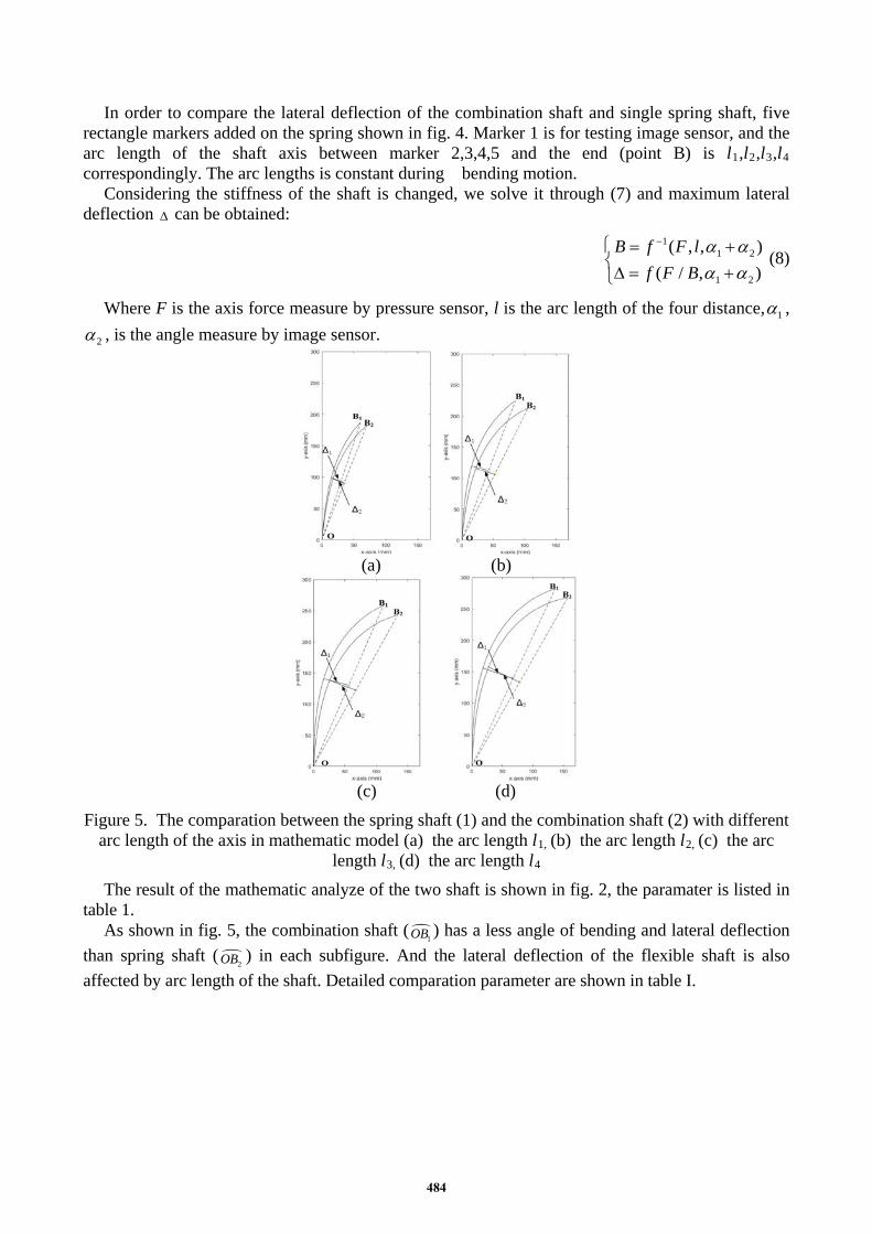
In order to compare the lateral deflection of the combination shaft and single spring shaft, five rectangle markers added on the spring shown in fig. 4. Marker 1 is for testing image sensor, and the arc length of the shaft axis between marker 2,3,4,5 and the end (point B) is l1,l2,l3,l4 correspondingly. The arc lengths is constant during bending motion.
Considering the stiffness of the shaft is changed, we solve it through (7) and maximum lateral deflection ∆ can be obtained:
11 2
1 2
( , , )( / , )
B f F lf F B
α αα α
− = +∆ = +
(8)
Where F is the axis force measure by pressure sensor, l is the arc length of the four distance, 1α ,
2α , is the angle measure by image sensor.
(a) (b)
(c) (d)
Figure 5. The comparation between the spring shaft (1) and the combination shaft (2) with different arc length of the axis in mathematic model (a) the arc length l1, (b) the arc length l2, (c) the arc
length l3, (d) the arc length l4 The result of the mathematic analyze of the two shaft is shown in fig. 2, the paramater is listed in
table 1. As shown in fig. 5, the combination shaft (
1OB ) has a less angle of bending and lateral deflection than spring shaft (
2OB ) in each subfigure. And the lateral deflection of the flexible shaft is also affected by arc length of the shaft. Detailed comparation parameter are shown in table I.
484
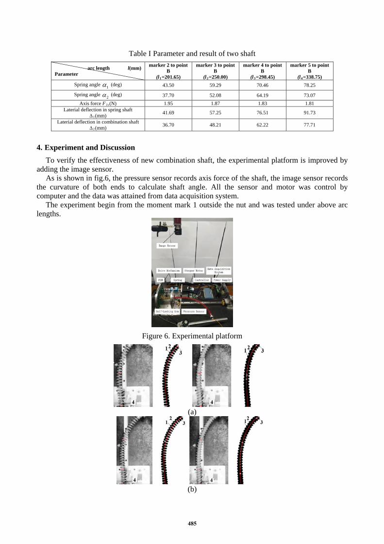
Table I Parameter and result of two shaft
arc length l(mm) Parameter
marker 2 to point B
(l1=201.65)
marker 3 to point B
(l2=250.00)
marker 4 to point B
(l3=298.45)
marker 5 to point B
(l4=338.75) Spring angle 1α (deg) 43.50 59.29 70.46 78.25
Spring angle 2α (deg) 37.70 52.08 64.19 73.07 Axis force F1x(N) 1.95 1.87 1.83 1.81
Laterial deflection in spring shaft ∆1(mm) 41.69 57.25 76.51 91.73
Laterial deflection in combination shaft ∆2(mm) 36.70 48.21 62.22 77.71
4. Experiment and Discussion To verify the effectiveness of new combination shaft, the experimental platform is improved by
adding the image sensor. As is shown in fig.6, the pressure sensor records axis force of the shaft, the image sensor records
the curvature of both ends to calculate shaft angle. All the sensor and motor was control by computer and the data was attained from data acquisition system.
The experiment begin from the moment mark 1 outside the nut and was tested under above arc lengths.
Figure 6. Experimental platform
(a)
(b)
485

(c)
(d)
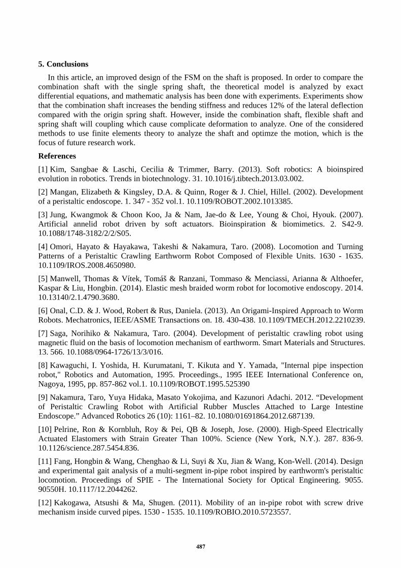
Figure 7. The comparation between the spring shaft (left side) and the combination shaft(right side) with different arc length of the axis in experiment 1. shaft morphology 2.equivalent bar 3.fitting
curve 4.marker in use (a) the arc length l1 , (b) the arc length l2, (c) the arc length l3, (d) the arc length l4
From each subfigure in Fig.7, spring shaft and combination shaft in experiment is shown, right after the shaft is the figure of the shaft with a fitting curve and equivalent bar add on the origin image processing one.
By measuring the maximum lateral deflection of the shaft in the experiment, together with simulation results in table II, the variation of the maximum lateral deflection is compared as follow.
Table II The experiment reslut of two shaft
Arc length l(mm) Laterial deflection
marker 2 to point B
(l1=201.65)
marker 3 to point B
(l2=250.00)
marker 4 to point B
(l3=298.45)
marker 5 to point B
(l4=338.75) Spring shaft in theory
∆1(mm) 41.69 57.25 76.51 91.73
combination shaft in theory ∆1(mm) 36.70 48.21 62.22 77.71
Spring shaft in experiment ∆2(mm) 41.50 54.75 71.30 84.60
combination shaft in experiment
∆2(mm) 36.75 46.85 57.70 71.15
As shown in table II, the maximum laterial deflection in combination shaft decrease 12 % more than spring shaft. It proves that the FSM with combination shaft leads less bending energy and more effective motion than with spring shaft.
Besides, laterial deflection of both shafts in experiment decrease compared with the shaft in theory. The decrease is caused by the friction in the platform and the coupling between the mechanisms.
486
5. Conclusions In this article, an improved design of the FSM on the shaft is proposed. In order to compare the
combination shaft with the single spring shaft, the theoretical model is analyzed by exact differential equations, and mathematic analysis has been done with experiments. Experiments show that the combination shaft increases the bending stiffness and reduces 12% of the lateral deflection compared with the origin spring shaft. However, inside the combination shaft, flexible shaft and spring shaft will coupling which cause complicate deformation to analyze. One of the considered methods to use finite elements theory to analyze the shaft and optimze the motion, which is the focus of future research work. References [1] Kim, Sangbae & Laschi, Cecilia & Trimmer, Barry. (2013). Soft robotics: A bioinspired evolution in robotics. Trends in biotechnology. 31. 10.1016/j.tibtech.2013.03.002. [2] Mangan, Elizabeth & Kingsley, D.A. & Quinn, Roger & J. Chiel, Hillel. (2002). Development of a peristaltic endoscope. 1. 347 - 352 vol.1. 10.1109/ROBOT.2002.1013385. [3] Jung, Kwangmok & Choon Koo, Ja & Nam, Jae-do & Lee, Young & Choi, Hyouk. (2007). Artificial annelid robot driven by soft actuators. Bioinspiration & biomimetics. 2. S42-9. 10.1088/1748-3182/2/2/S05. [4] Omori, Hayato & Hayakawa, Takeshi & Nakamura, Taro. (2008). Locomotion and Turning Patterns of a Peristaltic Crawling Earthworm Robot Composed of Flexible Units. 1630 - 1635. 10.1109/IROS.2008.4650980. [5] Manwell, Thomas & Vítek, Tomáš & Ranzani, Tommaso & Menciassi, Arianna & Althoefer, Kaspar & Liu, Hongbin. (2014). Elastic mesh braided worm robot for locomotive endoscopy. 2014. 10.13140/2.1.4790.3680. [6] Onal, C.D. & J. Wood, Robert & Rus, Daniela. (2013). An Origami-Inspired Approach to Worm Robots. Mechatronics, IEEE/ASME Transactions on. 18. 430-438. 10.1109/TMECH.2012.2210239. [7] Saga, Norihiko & Nakamura, Taro. (2004). Development of peristaltic crawling robot using magnetic fluid on the basis of locomotion mechanism of earthworm. Smart Materials and Structures. 13. 566. 10.1088/0964-1726/13/3/016. [8] Kawaguchi, I. Yoshida, H. Kurumatani, T. Kikuta and Y. Yamada, "Internal pipe inspection robot," Robotics and Automation, 1995. Proceedings., 1995 IEEE International Conference on, Nagoya, 1995, pp. 857-862 vol.1. 10.1109/ROBOT.1995.525390 [9] Nakamura, Taro, Yuya Hidaka, Masato Yokojima, and Kazunori Adachi. 2012. “Development of Peristaltic Crawling Robot with Artificial Rubber Muscles Attached to Large Intestine Endoscope.” Advanced Robotics 26 (10): 1161–82. 10.1080/01691864.2012.687139. [10] Pelrine, Ron & Kornbluh, Roy & Pei, QB & Joseph, Jose. (2000). High-Speed Electrically Actuated Elastomers with Strain Greater Than 100%. Science (New York, N.Y.). 287. 836-9. 10.1126/science.287.5454.836. [11] Fang, Hongbin & Wang, Chenghao & Li, Suyi & Xu, Jian & Wang, Kon-Well. (2014). Design and experimental gait analysis of a multi-segment in-pipe robot inspired by earthworm's peristaltic locomotion. Proceedings of SPIE - The International Society for Optical Engineering. 9055. 90550H. 10.1117/12.2044262. [12] Kakogawa, Atsushi & Ma, Shugen. (2011). Mobility of an in-pipe robot with screw drive mechanism inside curved pipes. 1530 - 1535. 10.1109/ROBIO.2010.5723557.
487

[13] Zhang Y, Xu J, Wang W. Kinematics and Force Analysis of Flexible Screw Mechanism for a Worm Robot. ASME. J. Mechanisms Robotics. 2018;10(6):061005-061005-7. [14] Zhang, Yanheng & Feng, Wenlong & Nian, Sicheng & Sun, Hanxu. (2013). Traction Force and Flexible Shaft Stability Analysis of Flexible Squirming Pipe Robot. Robot. 35. 477. 10.3724/SP.J.1218.2013.00477. [15] Krużelecki, J & Życzkowski, Michal. (1990). On the concept of an equivalent column in the stability problem of compressed helical springs. Archive of Applied Mechanics. 60. 367-377. 10.1007/BF00542566.
488