Improved Adaptive Beamforming for Smart Antennas
12
Improved Adaptive Beamforming for Smart Antennas Veerendra Dakulagi ( [email protected] ) Guru Nanak Dev Engineering College https://orcid.org/0000-0003-1056-0004 Rohini Dakulagi Guru Nanak Dev Engineering College Kim Ho Yeap UniversitiTunku Abdul Rahman Humaira Nisar UniversitiTunku Abdul Rahman Research Article Keywords: Adaptive beamforming, LMS, NLMS, VSSNLMS, ULA. Posted Date: July 13th, 2021 DOI: https://doi.org/10.21203/rs.3.rs-684387/v1 License: This work is licensed under a Creative Commons Attribution 4.0 International License. Read Full License
Transcript of Improved Adaptive Beamforming for Smart Antennas

Improved Adaptive Beamforming for SmartAntennasVeerendra Dakulagi ( [email protected] )
Guru Nanak Dev Engineering College https://orcid.org/0000-0003-1056-0004Rohini Dakulagi
Guru Nanak Dev Engineering CollegeKim Ho Yeap
UniversitiTunku Abdul RahmanHumaira Nisar
UniversitiTunku Abdul Rahman
Research Article
Keywords: Adaptive beamforming, LMS, NLMS, VSSNLMS, ULA.
Posted Date: July 13th, 2021
DOI: https://doi.org/10.21203/rs.3.rs-684387/v1
License: This work is licensed under a Creative Commons Attribution 4.0 International License. Read Full License

Improved Adaptive Beamforming for Smart
Antennas
Veerendra Dakulagi1, Rohini Dakulagi2 Kim Ho Yeap3, and Humaira Nisar3, 1Dept. of Electronics & Communication Engg., Guru Nanak Dev Engineering College,
Bidar, Mailoor Road, Bidar 585403, Karnataka, India. 2Dept. of Electrical and Electronics Engg., Guru Nanak Dev Engineering College,
Bidar, Mailoor Road, Bidar 585403, Karnataka, India. 3Faculty of Engineering and Green Technology, UniversitiTunku Abdul Rahman,
31900 Kampar, Malaysia.
Email: [email protected], [email protected] [email protected], [email protected]
Abstract--In this paper, we propose a new antenna array configuration for smart antenna
beamforming. In this new method, we displace two antenna elements of a uniform linear array
(ULA) and place them at the top and bottom of the array axis. We investigate the efficacy of this
method by deploying the variable step size least mean square algorithm (VSSLMS). The proposed
method is compared with popular LMS and normalized LMS algorithms. Computer simulations
show that the proposed method has enhanced convergence rate and high data transmission
compared to the LMS and the NLMS methods. Also, the new method has the same performance for
middle angles, near boresight and array endfires which is not possible for the LMS and the NLMS
method using a ULA.
Keywords: Adaptive beamforming, LMS, NLMS, VSSNLMS, ULA.
1. Introduction
Smart antennas have long been an attractive solution to plethora of problems related to signal
detection, estimation and beamforming. The smart antenna system which consists of an array of
antenna elements with signal processing capabilities can overcome the directivity and beamwidth
limitations of a single antenna element, and when it combined with methods from statistical
detection and estimation and control theory, a self- adjusting or adaptive system emerges.
Adaptive beamforming algorithms have been widely used in various wireless applications
including radar [1], satellite [2], sonar [3], seismology [4], astrophysics [5], etc. Among the
numerous approaches, LMS [6]-[7], NLMS [8] and variable step-size LMS [9] are the most
popular methods. These methods use the constant step size for beamforming and require more
samples.
In practice, for smart beamforming, the step size should be adaptive instead of constant. Also, in
certain cases, only a few samples number is available at the receiver. In such cases, the
performance of the LMS, NLMS, and SMI deteriorates. This problem can be circumvented by
making the step size adaptive.
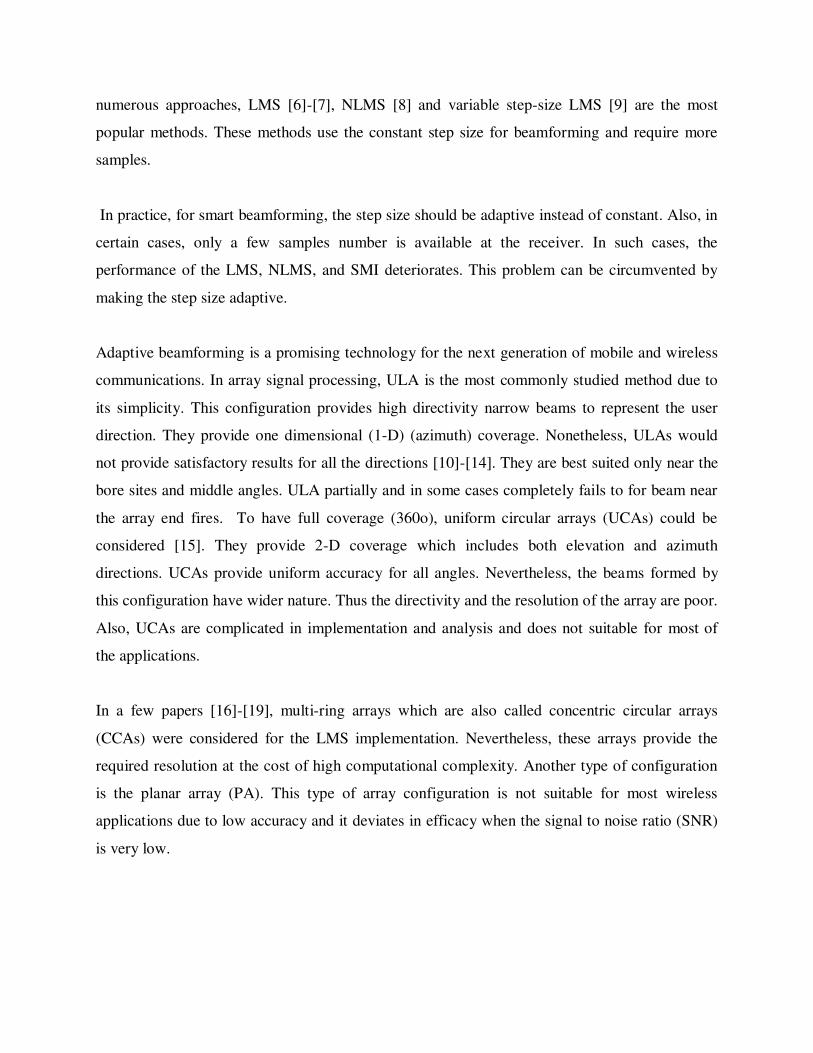
Adaptive beamforming is a promising technology for the next generation of mobile and wireless
communications. In array signal processing, ULA is the most commonly studied method due to
its simplicity. This configuration provides high directivity narrow beams to represent the user
direction. They provide one dimensional (1-D) (azimuth) coverage. Nonetheless, ULAs would
not provide satisfactory results for all the directions [10]-[14]. They are best suited only near the
bore sites and middle angles. ULA partially and in some cases completely fails to for beam near
the array end fires. To have full coverage (360o), uniform circular arrays (UCAs) could be
considered [15]. They provide 2-D coverage which includes both elevation and azimuth
directions. UCAs provide uniform accuracy for all angles. Nevertheless, the beams formed by
this configuration have wider nature. Thus the directivity and the resolution of the array are poor.
Also, UCAs are complicated in implementation and analysis and does not suitable for most of
the applications.
In a few papers [16]-[19], multi-ring arrays which are also called concentric circular arrays
(CCAs) were considered for the LMS implementation. Nevertheless, these arrays provide the
required resolution at the cost of high computational complexity. Another type of configuration
is the planar array (PA). This type of array configuration is not suitable for most wireless
applications due to low accuracy and it deviates in efficacy when the signal to noise ratio (SNR)
is very low.

Recently, displaced antenna arrays (DAAs) [20], L-shaped array, V-shaped array, hexagonal
arrays have been proposed for smart antenna beamforming. However, all these types can provide
the 2-D signal estimation and are applicable in specific applications.
The LMS beamformer is the most commonly used beamformer in many wireless applications
including military surveillances and mobile communications due to its simplicity. This
beamformer needs just O(M) flops to compute the complex array weights. Here, M represents the
antenna array size. Nevertheless, its application in a few systems is hindered due to very slow
convergence speed. This beamformer needs more than 90 iterations to converge the error
between the desired and a reference signal. The slow convergence affects the performance of the
algorithm when a signal is changing rapidly. Thus, the LMS method is not suitable for current
and future communication systems.
The problem of slow convergence is circumvented to some extent in the NLMS algorithm [21]-
[22]. The fast convergence is ached in this technique by avoiding the computation of
eigenvalues. This beamformer is not sensitive and also immune to interferences due to
normalization.
However, in [23], it has been shown that this method has certain implementation issues. A few
issues are:
1. Miss-adjustment noise.
2. Variation in antenna array weights.
To, overcome the downsides of the LMS and NLMS methods, recently VSSNLMS algorithm is
presented. In our work, we use a modified ULA in which the first and last elements are placed at
the top and bottom of the array axis. We deploy the VSSNLMS algorithm for beamforming.
Simulation results are compared with the popular LMS and the NLMS beamformers.
2. The proposed Array signal model for VSSNLMS
Figure 1 shows the configuration of the ULA which composed of M antenna elements with a
2/d as a inter element spacing to avoid mutual coupling and grating lobes in adaptive beam

forming. We assume N uncorrelated narrow band signals (M > N) impinge the ULA from far
fields from 1210 ,,,, N directions.
Figure 1: Classical ULA configuration.
The signal received at the ULA is represented as
nnsn n
N
n
n nax
1
0
(1)
where nx is the M x 1 received vector.
nsn denotes the envelopes of the signal with n = 0, 1, 2,…, N-1.
na is the M x 1 steering vector, which is responsible for steering the beam in the desired
direction which is denoted as
TMdjdjee
/1sin2/sin2 ,,,1)( a
(2)
nn is the M x 1 white Gaussian noise with 2 variance and zero mean.
Equation (1) denotes the vector form of the received signal. The vector and matrix form of (1)
can be written as
nnsn n nAx (3)
where A is the M x N manifold of steering vector known as Vondermonde matrix represented as
N aaaA ,,, 21 (4)
In our work, a modified ULA is represented by displacing the first and last elements at the top
and bottom of the ULA as shown in Figure 2.

Figure 2: Modified ULA configuration.
The steering vector of the modified ULA consists of (2) with two extra rows for the antennas
placed at the top and bottom of the array axis. That is,
T
djkdk
Mj
djkdk
Mj
new
ee
ee
cos
sin2
1
cossin
2
1
)(
)(
a
a
(5)
Now, the new Vondermonde matrix for the manifold of all steering vectors of (5) is
Nnewnewnew aaaA ,,,ˆ21 (6)
The weights update equation of this algorithm is expressed as:
nne
nenenene
nnn xww *
*
1
*
1
)()()(1)()(
)()1(
(7)
here
001.0
66)(
22
Mj
Mn
(8)
Here: n is the step size and 1 is the shaping parameter =0.1
w (n) is the previous weights
w(n+1) is the updated array weights
The error signal e(n) is the difference between the desired signal d(n) and the array output y(n).
nyndne )(
(10)
The output of the signal is given by
nnnyH
xw
(11)
Finally, the array pattern is calculated as
new
Hn awp
(12)
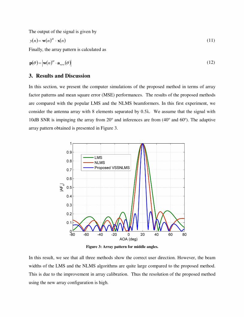
3. Results and Discussion
In this section, we present the computer simulations of the proposed method in terms of array
factor patterns and mean square error (MSE) performances. The results of the proposed methods
are compared with the popular LMS and the NLMS beamformers. In this first experiment, we
consider the antenna array with 8 elements separated by 0.5λ. We assume that the signal with
10dB SNR is impinging the array from 20o and inferences are from (40o and 60o). The adaptive
array pattern obtained is presented in Figure 3.
Figure 3: Array pattern for middle angles.
In this result, we see that all three methods show the correct user direction. However, the beam
widths of the LMS and the NLMS algorithms are quite large compared to the proposed method.
This is due to the improvement in array calibration. Thus the resolution of the proposed method
using the new array configuration is high.
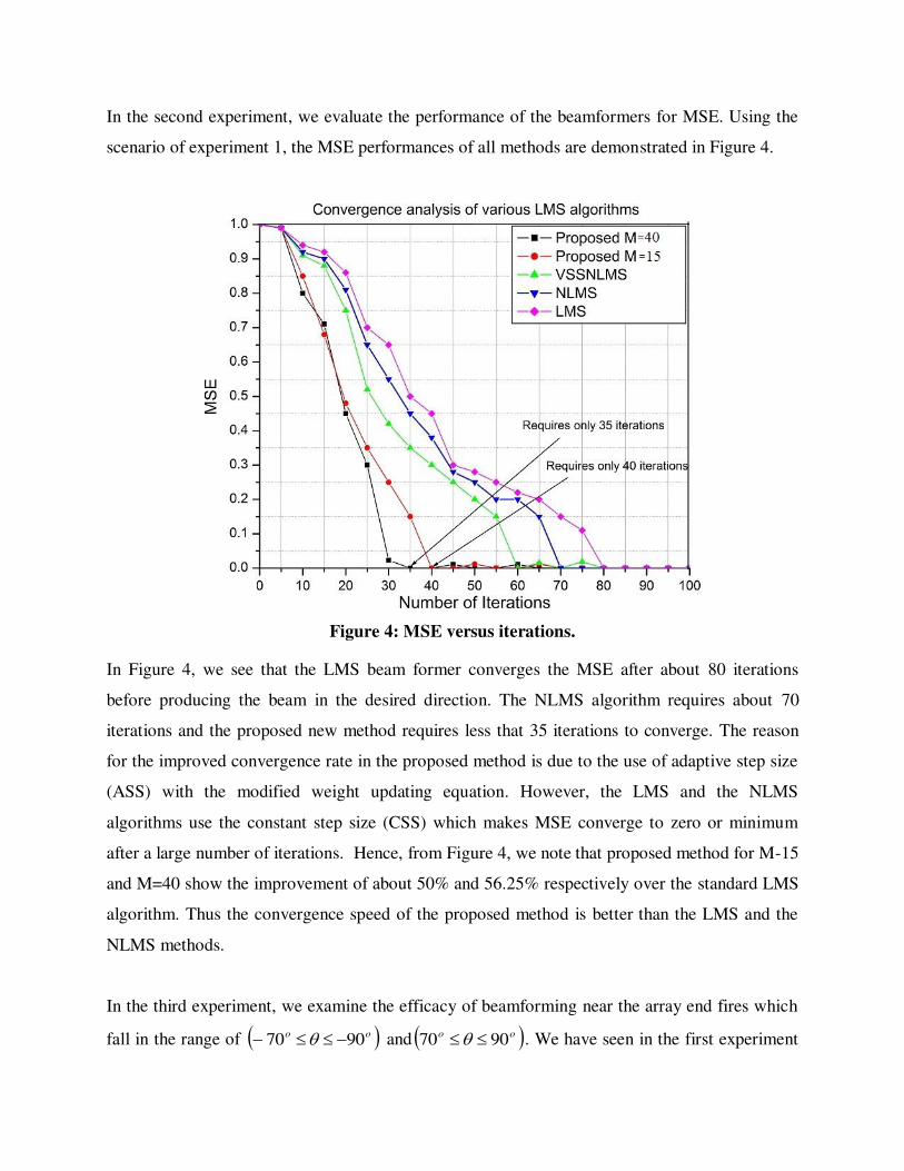
In the second experiment, we evaluate the performance of the beamformers for MSE. Using the
scenario of experiment 1, the MSE performances of all methods are demonstrated in Figure 4.
Figure 4: MSE versus iterations.
In Figure 4, we see that the LMS beam former converges the MSE after about 80 iterations
before producing the beam in the desired direction. The NLMS algorithm requires about 70
iterations and the proposed new method requires less that 35 iterations to converge. The reason
for the improved convergence rate in the proposed method is due to the use of adaptive step size
(ASS) with the modified weight updating equation. However, the LMS and the NLMS
algorithms use the constant step size (CSS) which makes MSE converge to zero or minimum
after a large number of iterations. Hence, from Figure 4, we note that proposed method for M-15
and M=40 show the improvement of about 50% and 56.25% respectively over the standard LMS
algorithm. Thus the convergence speed of the proposed method is better than the LMS and the
NLMS methods.
In the third experiment, we examine the efficacy of beamforming near the array end fires which
fall in the range of oo 9070 and oo 9070 . We have seen in the first experiment

that all three methods have provided the required angle of arrival estimation with good resolution
at middle angles oo 6060 and at boresites. In this case, we consider the same situation
of experiment 1 except that the signal is impinging the array at 78o and -80o. Computer
simulations for a signal with AOA=78o and -80o are respectively demonstrated in Figures 5 and
6.
Figure 5: Beam forming for array endfire (AOA=78o)
Figure 6: Beam forming for array endfire (AOA= -80o).
In Figure 5, we observe that the LMS and the NLMS algorithms make the incorrect AOA
estimation with broader beam width. This is because the array patterns of these methods are
drawn using classical ULA. Nevertheless, the modified array using the VSSLMS provided better
results near the array end fires and makes the correct estimation. The same remarks can be
drawn from Figure 6. Thus, this experiment shows that only the proposed method can form the
beams near and at the array end fires for estimating the AOA of the user. The performances of
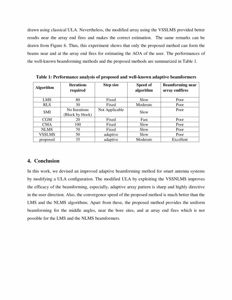
the well-known beamforming methods and the proposed methods are summarized in Table 1.
Table 1: Performance analysis of proposed and well-known adaptive beamformers
Algorithm Iterations
required
Step size Speed of
algorithm
Beamforming near
array endfires
LMS 80 Fixed Slow Poor
RLS 30 Fixed Moderate Poor
SMI No Iterations
(Block by block)
Not Applicable Slow
Poor
CGM 20 Fixed Fast Poor
CMA 100 Fixed Slow Poor
NLMS 70 Fixed Slow Poor
VSSLMS 50 adaptive Slow Poor
proposed 35 adaptive Moderate Excellent
4. Conclusion
In this work, we devised an improved adaptive beamforming method for smart antenna systems
by modifying a ULA configuration. The modified ULA by exploiting the VSSNLMS improves
the efficacy of the beamforming, especially, adaptive array pattern is sharp and highly directive
in the user direction. Also, the convergence speed of the proposed method is much better than the
LMS and the NLMS algorithms. Apart from these, the proposed method provides the uniform
beamforming for the middle angles, near the bore sites, and at array end fires which is not
possible for the LMS and the NLMS beamformers.

ACKNOWLEDGEMENT
This work was supported in by the VISION GROUP ON SCIENCE AND TECHNOLOGY,
GOVERNMENT OF KARNATAKA, INDIA RESEARCH FUND UNDER RGS/F SCHEME 2019-2020
(GRD No. 906).
.
Declarations:
Compliance with Ethical Standards
Conflict of interest: The authors declare that they have no conflict of interest.
Funding: This work was supported in by the Vision Group on Science and Technology,
Government of Karnataka, India research fund under RGS/F scheme 2019-2020 (GRD No.
906).
Availability of data and material: Not applicable
Code availability: Not applicable
References
[1] S. Biswas, J. Xue, F. A. Khan and T. Ratnarajah, "Performance Analysis of Correlated Massive MIMO
Systems With Spatially Distributed Users", IEEE Systems Journal, vol. 12, no. 2, pp. 1850-1861, June 2018.
[2] Molisch, V. Ratnam, S. Han, Z. Li, S. Le Hong Nguyen, L. Li, et al., "Hybrid Beamforming for Massive
MIMO: A Survey", IEEE Communications Magazine, Sep 2017.
[3] S. Kutty and D. Sen, "Beamforming for Millimeter Wave Communications: An Inclusive Survey", IEEE
Communications Surveys & Tutorials, vol. 18, no. 2, pp. 949-973, 2016.
[4] Sergiy A. Vorobyov, “Array and statistical signal processing”, Elsevier Signal Processing, Vol .3, pp.1-51,
2014.
[5] X. Fu, R. Cao, and F. Wen, “A de-noising 2-D-DOA estimation method for uniform rectangle array,” IEEE
Commun. Lett., vol. 22, no. 9, pp.1854–1857, Sep. 2018.
[6] B. Jalal, X. Yang, X. Wu, T. Long and T. K. Sarkar, "Efficient Direction-of-Arrival Estimation Method
Based on LMS Algorithm," IEEE Antennas Wireless Propag. Lett., vol. 18, no. 8, pp. 1576-1580, Aug.
2019. [7] B. Jalal, X. Yang, Q. Liu, T. Long and T. K. Sarkar, "Fast and Robust Variable-Step-Size LMS Algorithm
for Adaptive Beamforming," IEEE Antennas and Wireless Propagation Letters, vol. 19, no. 7, pp. 1206-
1210, July 2020.
[8] R. Y. Chen and C. L. Wang, “On the optimum step size for the adaptive sign and LMS algorithms,” IEEE
Trans. Circuits Syst., vol. 37, pp. 836–840, 1990.
[9] H. C. Huang and J. Lee, "A new variable step-size NLMS algorithm and its performance analysis", IEEE
Trans. Signal Process., vol. 60, no. 4, pp. 2055-2060, Apr. 2012.
[10] J. H. Winters, “Optimum combining for indoor radio systems with multiple users,” IEEE Trans. Commun.,
vol. COM-35, pp. 1222–1230, 1987.
[11] V. J. Mathews and S. H. Cho, “Improved convergence analysis of stochastic gradient adaptive filters using
the sign algorithm,” IEEE Trans. Acoust., Speech, Signal Processing, vol. ASSP-35, pp. 450–454, 1987. [12] M. A. Jones and M. A. Wickert, “Direct sequence spread spectrum using directionally constrained adaptive
beamforming to null interference,” IEEE J. Select. Areas Commun., vol. 13,pp. 71–79, 1995.
[13] D. T. M. Slock, “On the convergence behavior of the LMS and the normalized LMS algorithms,” IEEE
Trans. Signal Processing, vol. 41, pp. 2811–2825, 1993.
[14] M. Rupp, “The behavior of LMS and NLMS algorithms in the presence of spherically invariant processes,” IEEE Trans. Signal Processing, vol. 41, pp. 1149–1160, 1993.

[15] M. Askari, M. Karimi and Z. Atbaee, "Robust beamforming in circular arrays using phase-mode
transformation", IET Signal Processing, vol. 7, no. 8, pp. 693-703, 2013.
[16] M. F. Reza, M. S. Hossain, M. T. Hossein and M. M. Rashid, "Robust uniform concentric circular array beamforming in the existence of look direction disparity," 2016 2nd International Conference on
Electrical, Computer & Telecommunication Engineering (ICECTE), Rajshahi, 2016, pp. 1-4.
[17] R. L. Haupt, "Optimized element spacing for low sidelobe concentric ring arrays", IEEE Transactions on
Antennas and Propagation, vol. 56, no. 1, pp. 266-268, 2008.
[18] M. Carlin, G. Oliveri and A. Massa, "Hybrid BCS-Deterministic Approach for Sparse Concentric Ring
Isophoric Arrays", IEEE transactions on antenna and propagation, vol. 63, no. 1, January 2015.
[19] R. Kulaib, R. M. Shubair, M. Al-Qutayri and J. Ng, "Accurate and Robust DOA Estimation Using Uniform
Circular Displaced Antenna Array", 2015 IEEE International Symposium on Antennas and Propagation,
pp. 1552-1553, 2015.
[20] K. Hoshino, S. Sudo and Y. Ohta, "A Study on Antenna Beamforming Method Considering Movement of
Solar Plane in HAPS System," 2019 IEEE 90th Vehicular Technology Conference (VTC2019-Fall), Honolulu, HI, USA, 2019, pp. 1-5.
[21] D. T. M. Slock, “On the convergence behavior of the LMS and the normalized LMS algorithms,” IEEE Trans. Signal Processing, vol. 41, pp. 2811–2825, 1993.
[22] M. Rupp, “The behavior of LMS and NLMS algorithms in the presence of spherically invariant processes,” IEEE Trans. Signal Processing, vol. 41, pp. 1149–1160, 1993.
[23] M. Barrett and R. Arnott, “Adaptive antennas for mobile communications,” Electron. Commun. Eng. J.,
vol. 6, pp. 203–214, 1994.