Improve Water Quality by Cyclone Separator as a Pre ... · The solid liquid hydrocyclone separator...
8
Abstract—Increasing the needs to drinking, purified water impose constructing new water treatment plants, which needs big expenditures due to the operation and maintenance and consumable material costs such as Alum Sulphate used in the settling activities in addition to the costs of operation and maintenance of settlers. The using of hydrocylone as a pre-filtering system has been studied in this paper. Series of tests (runs) has been carried out on a designated hydrocylone with diameter of 85mm and total length of 510mm which is convenience to a pumping rate of 50 L/min and pressure of 150,000 Pascal. To investigate the results, a mobile turbidity meter has been used to measure the turbidity and Bettersize particles size analyzer has been used to investigate particles distribution which caused each turbidity for both inlet feed water and overflow water. For all runs, the hydrocylone results showed that the used hydrocylone recovered 84.6% of the feed water through the overflow outlet and recovered 15.4% through the underflow outlet, it is started with a feed water turbidity of 300NTU, and the hydrocylone concentrated the solids loaded in the raw water by 155.66% and reduced the turbidity by 52.33%. The results of the present work indicated that the usage of hydrocyclone can efficiently reduce the solid loading of raw water pumped into a water treatment facility, the grade removal efficiency are affected by the phenomena of collision and agglomeration of particles inside the hydrocyclone which will change the size distribution of a specific grades. The x50 of in the experiment was (37μm) and the hydrocyclone succeed in removing 42.6% of the suspended solids fed with the inlet feed. And it removed 47.3% of the settable solids. It is also clear that the hydrocyclone succeed in lowering the mean diameter of solids in the overflow to 35.41μm from 75.11μm, i.e. the hydrocyclone succeed to reduce the mean by 53.25%. Keywords---Hydrocyclone, pre-filtering, turbidity reduction. I. INTRODUCTION ITH the rising of water shortage problems and decreasing of water resources due to climate changes, the need for using all type of available water is increased, such as the re-treatment of waste water; increase the independent on water wells, water disposed from different industries such as pulp industry etc, usually these types of water brings different types of suspended solids, the hydrocyclone come into existence as a sound and proved technological alternative in separation these solids from water. Hydrocyclones have been Dr. Alaa Husaeen Wadie Al-Fatlawi (PhD.), Environmental Engineering Department, College of Engineering, University of Babylon, Iraq. Phone: (+964) (0) (7801595607), Email: [email protected] Eng.Osamah Al-Hashimi (M.Sc.), Environmental Engineering, University of Babylon, Iraq. Phone: (+964) (0) (7700084502), Email: ausama.ali@ gmail.com. widely used for various applications and by different industries, including the mineral, chemical petrochemical, petroleum, food and drug, pulp and paper, environmental, and biology, among others (Rama and Udaya, 2012)[1]. Common hydrocyclone applications include classification of solids or removal of particulates from a liquid or a gas stream. The use of the solid-liquid hydrocyclone has emerged as a sound alternative to conventional filtration and other separation systems, which are bulky, require backwashing, frequent replacement of filters, chemical additives, and have greater pressure drop, resulting in higher operating costs. The petroleum industry, for example, has utilized the solid-liquid hydrocyclone to remove oilfield solids from produced water in order to make it suitable for down-hole re-injection, either for reservoir water flooding or for disposal. Hydrocyclones are also an attractive solution for offshore applications where space, efficiency, and reliability are important (Gómez, 2001)[2]. Different types of hydrocyclones have been used by the industry in the past to separate solid-solid (classifiers), liquid- liquid, gas-liquid, gas-solid, and solid-liquid mixtures. This paper focuses on the application of hydrocyclone in the field of water treatment and how the use of hydrocyclone can improve the operation of water treatment facility and reduce the cost of operation by reducing the turbidity of water pumped into the treatment facility. In the water industry there is a wide use to the conventional gravity based vessels which are bulky, heavy and expensive to separate multiphase flow. The difficulty and the cost of accommodate these separation facilities has provided the incentive for development of compact separation technology, hydrocyclones have emerged as an economical and effective alternate for produced water and other applications, the hydrocyclone is inexpensive, simple in design with no moving parts, easy to install and operate, and has low maintenance cost (E. Endres, etal. 2001)[3]. Instead of the previous literatures available on the hydrocyclone, there is still an insisting need for more comprehensive studies and data sets, including as an example the use of new measuring apparatus (such as the “Bettersize 2000 Intelligent Laser Particle Size Analyzer” used in this paper) and the simulation of hydrocyclone using the modern computer software in the computational fluid dynamic (such as Ansys Fluent software) which gives a detailed illustration for what is going inside the hydrocyclone during operation. In Improve Water Quality by Cyclone Separator as a Pre-Treatment Technique Dr. Alaa Hussein Wadi Al-Fatlawi, and Osamah Ali Hadi Al-Hashimi W International Journal of Chemical, Environmental & Biological Sciences (IJCEBS) Volume 1, Issue 4 (2013) ISSN 2320-4079; EISSN 2320–4087 576
Transcript of Improve Water Quality by Cyclone Separator as a Pre ... · The solid liquid hydrocyclone separator...
Abstract—Increasing the needs to drinking, purified water
impose constructing new water treatment plants, which needs big expenditures due to the operation and maintenance and consumable material costs such as Alum Sulphate used in the settling activities in addition to the costs of operation and maintenance of settlers. The using of hydrocylone as a pre-filtering system has been studied in this paper. Series of tests (runs) has been carried out on a designated hydrocylone with diameter of 85mm and total length of 510mm which is convenience to a pumping rate of 50 L/min and pressure of 150,000 Pascal. To investigate the results, a mobile turbidity meter has been used to measure the turbidity and Bettersize particles size analyzer has been used to investigate particles distribution which caused each turbidity for both inlet feed water and overflow water.
For all runs, the hydrocylone results showed that the used hydrocylone recovered 84.6% of the feed water through the overflow outlet and recovered 15.4% through the underflow outlet, it is started with a feed water turbidity of 300NTU, and the hydrocylone concentrated the solids loaded in the raw water by 155.66% and reduced the turbidity by 52.33%. The results of the present work indicated that the usage of hydrocyclone can efficiently reduce the solid loading of raw water pumped into a water treatment facility, the grade removal efficiency are affected by the phenomena of collision and agglomeration of particles inside the hydrocyclone which will change the size distribution of a specific grades. The x50 of in the experiment was (37μm) and the hydrocyclone succeed in removing 42.6% of the suspended solids fed with the inlet feed. And it removed 47.3% of the settable solids. It is also clear that the hydrocyclone succeed in lowering the mean diameter of solids
in the overflow to 35.41μm from 75.11μm, i.e. the hydrocyclone succeed to reduce the mean by 53.25%.
Keywords---Hydrocyclone, pre-filtering, turbidity reduction.
I. INTRODUCTION ITH the rising of water shortage problems and decreasing of water resources due to climate changes,
the need for using all type of available water is increased, such as the re-treatment of waste water; increase the independent on water wells, water disposed from different industries such as pulp industry etc, usually these types of water brings different types of suspended solids, the hydrocyclone come into existence as a sound and proved technological alternative in separation these solids from water. Hydrocyclones have been
Dr. Alaa Husaeen Wadie Al-Fatlawi (PhD.), Environmental Engineering Department, College of Engineering, University of Babylon, Iraq. Phone: (+964) (0) (7801595607), Email: [email protected]
Eng.Osamah Al-Hashimi (M.Sc.), Environmental Engineering, University of Babylon, Iraq. Phone: (+964) (0) (7700084502), Email: ausama.ali@ gmail.com.
widely used for various applications and by different industries, including the mineral, chemical petrochemical, petroleum, food and drug, pulp and paper, environmental, and biology, among others (Rama and Udaya, 2012)[1].
Common hydrocyclone applications include classification of solids or removal of particulates from a liquid or a gas stream. The use of the solid-liquid hydrocyclone has emerged as a sound alternative to conventional filtration and other separation systems, which are bulky, require backwashing, frequent replacement of filters, chemical additives, and have greater pressure drop, resulting in higher operating costs. The petroleum industry, for example, has utilized the solid-liquid hydrocyclone to remove oilfield solids from produced water in order to make it suitable for down-hole re-injection, either for reservoir water flooding or for disposal. Hydrocyclones are also an attractive solution for offshore applications where space, efficiency, and reliability are important (Gómez, 2001)[2].
Different types of hydrocyclones have been used by the industry in the past to separate solid-solid (classifiers), liquid-liquid, gas-liquid, gas-solid, and solid-liquid mixtures. This paper focuses on the application of hydrocyclone in the field of water treatment and how the use of hydrocyclone can improve the operation of water treatment facility and reduce the cost of operation by reducing the turbidity of water pumped into the treatment facility. In the water industry there is a wide use to the conventional gravity based vessels which are bulky, heavy and expensive to separate multiphase flow. The difficulty and the cost of accommodate these separation facilities has provided the incentive for development of compact separation technology, hydrocyclones have emerged as an economical and effective alternate for produced water and other applications, the hydrocyclone is inexpensive, simple in design with no moving parts, easy to install and operate, and has low maintenance cost (E. Endres, etal. 2001)[3].
Instead of the previous literatures available on the hydrocyclone, there is still an insisting need for more comprehensive studies and data sets, including as an example the use of new measuring apparatus (such as the “Bettersize 2000 Intelligent Laser Particle Size Analyzer” used in this paper) and the simulation of hydrocyclone using the modern computer software in the computational fluid dynamic (such as Ansys Fluent software) which gives a detailed illustration for what is going inside the hydrocyclone during operation. In
Improve Water Quality by Cyclone Separator as a Pre-Treatment Technique
Dr. Alaa Hussein Wadi Al-Fatlawi, and Osamah Ali Hadi Al-Hashimi
W
International Journal of Chemical, Environmental & Biological Sciences (IJCEBS) Volume 1, Issue 4 (2013) ISSN 2320-4079; EISSN 2320–4087
576
addition, in this paper, it has been used a data set from Al-Hillah river which is the main source of the most water treatment plants in Babylon province in Iraq.
II. OBJECTIVE OF STUDY The present work is aimed to discover the efficiency of a
hydrocyclone designated at specific pumping and pressure drop to reduce the turbidity of raw water, discovering the particle size distribution caused this turbidity. The magnitude of total, suspended, settleable, dissolved solids are part of this paper.
III. CONTRIBUTION OF THIS WORK TO THE WATER TREATMENT INDUSTRY
In the water treatment processes, the industry relies on the use of different filtering and separation devices, among which the solid liquid hydrocyclone offers important advantages. The solid liquid hydrocyclone is one of the most attractive technologies available owing to its low cost, simplicity of operation, acceptable reliability and good performance.
However, hydrocyclone technology needs to be improved in order to achieve higher performance levels for different applications and flow conditions.
According to (Syed R. Qasim)[4], in his textbook “Water Works Engineering Planning, Design & Operation – Copyright ©2000” “The design of a sedimentation basin is dependent upon the concentration, size, and behavior of the solid suspension”, in the present work, we don’t want to say that there is no need to construct a sedimentation tank if we used a hydrocyclone, but the operation cost will be reduced, logically, the amount of aluminum sulfate added to settle suspended solids in a raw water with specific turbidity will surely be more than the required amount of aluminum sulphate required to settle the suspended solids in a raw water with half of the said turbidity (This is one of the benefit of using a hydrocyclone after lifting pump station by utilize the power of pumping to reduce of pumped raw water turbidity).
IV. DESCRIPTION OF HYDROCYCLONE SEPARATORS The solid liquid hydrocyclone separator is a type of cyclone
that facilitates the centrifugal separation of solid particulates from a liquid stream; the hydrocyclone utilizes the energy obtained from fluid pressure to create rotational fluid motion, yielding much larger values of the g-force that can vary from 800g to about 50,000g. This high swirling motion is applied over a shorter residence time causing the particles suspended in the liquid to separate fast and effectively from the liquid itself (Rushton, et al., 1996)[5].
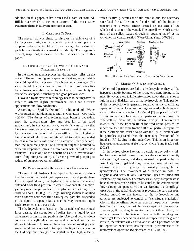
The hydrocyclone is based on the principle of centrifugal force causing the separation of solids from a liquid by the differences in density and particle size. A typical hydrocyclone consists of a cylindrical section and a conical section, as shown in Figure 1. It does not have any internal rotating parts. An external pump is used to transport the liquid suspension to the hydrocyclone through a tangential inlet at high velocity,
which in turn generates the fluid rotation and the necessary centrifugal force. The outlet for the bulk of the liquid is connected to a vortex finder located on the axis of the cylindrical section of the vessel. The underflow, which carries most of the solids, leaves through an opening (apex) at the bottom of the conical section (Wen-Ching Yang, 2003)[6].
Fig. 1 Hydrocyclone (a) schematic diagram (b) flow pattern
V. MOTION OF SUSPENDED PARTICLE When solid particles are fed to a hydrocyclone, they will be
dispersed rapidly because of the strong turbulent mixing at the inlet. However, there is little information about the behavior of fluid in the cylindrical part of the hydrocyclone. This portion of the hydrocyclone is generally regarded as the preliminary separation zone, while more thorough separation is thought to occur in the conical section. As Kelsel [7] proposed in 1952, "if fluid moves into the interior, all particles that exist near the cone wall can move into the interior rapidly". Therefore, it is obvious that if the fraction Rf of the feed liquid goes to the underflow, then the same fraction Rf of all particles, regardless of their settling rate, must also go with the liquid, together with the particles separated from the remaining fraction of the liquid (1–Rf) leaving in the underflow. This is an important diagnostic phenomenon of the hydrocyclone (Sang Huck Park, 2003)[8]
In the hydrocyclone interior, a particle at any point within the flow is subjected to two forces: acceleration due to gravity and centrifugal forces, and drag imposed on particle by the flow. Only centrifugal and drag forces are taken into account because effect of gravity is usually negligible in hydrocyclones. The movement of a particle in both the tangential and vertical (axial) directions does not encounter resistance by any forces. Therefore, its velocity components in those directions can be taken to be equal to the corresponding flow velocity components vt and va. Because the centrifugal force acts in the radial direction, it prevents the particles from flowing inward to the interior of the hydrocyclone and particles are subjected to control of "centrifugal elutriation" effect. If the centrifugal force that acts on the particle is greater than the drag force, the particle moves rapidly to the outside; conversely, if the drag is greater than centrifugal force, the particle moves to the inside. Because both the drag and centrifugal forces depend on vt and va respectively for given a particle, the relative values of va and vt of all positions within the separation zone detentions the overall performance of the hydrocyclone operation (Shojaeefard, et al, 2006)[9].
International Journal of Chemical, Environmental & Biological Sciences (IJCEBS) Volume 1, Issue 4 (2013) ISSN 2320-4079; EISSN 2320–4087
577
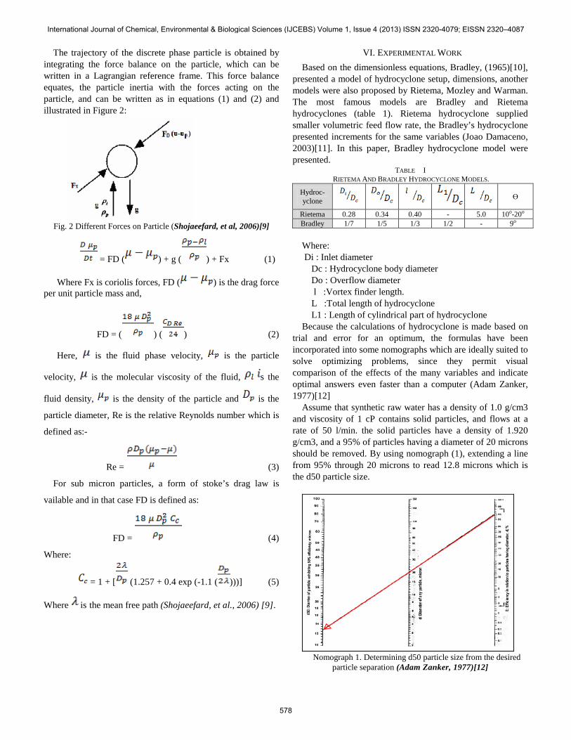
The trajectory of the discrete phase particle is obtained by integrating the force balance on the particle, which can be written in a Lagrangian reference frame. This force balance equates, the particle inertia with the forces acting on the particle, and can be written as in equations (1) and (2) and illustrated in Figure 2:
Fig. 2 Different Forces on Particle (Shojaeefard, et al, 2006)[9]
= FD ( ) + g ( ) + Fx (1)
Where Fx is coriolis forces, FD ( ) is the drag force per unit particle mass and,
FD = ( ) ( ) (2)
Here, is the fluid phase velocity, is the particle
velocity, is the molecular viscosity of the fluid, s the
fluid density, is the density of the particle and is the
particle diameter, Re is the relative Reynolds number which is
defined as:-
Re = (3)
For sub micron particles, a form of stoke’s drag law is
vailable and in that case FD is defined as:
FD = (4)
Where:
= 1 + [ (1.257 + 0.4 exp (-1.1 ( )))] (5)
Where is the mean free path (Shojaeefard, et al., 2006) [9].
VI. EXPERIMENTAL WORK Based on the dimensionless equations, Bradley, (1965)[10],
presented a model of hydrocyclone setup, dimensions, another models were also proposed by Rietema, Mozley and Warman. The most famous models are Bradley and Rietema hydrocyclones (table 1). Rietema hydrocyclone supplied smaller volumetric feed flow rate, the Bradley’s hydrocyclone presented increments for the same variables (Joao Damaceno, 2003)[11]. In this paper, Bradley hydrocyclone model were presented.
TABLE I RIETEMA AND BRADLEY HYDROCYCLONE MODELS.
Hydroc-yclone
Ө
Rietema 0.28 0.34 0.40 - 5.0 10o-20o
Bradley 1/7 1/5 1/3 1/2 - 9o
Where: Di : Inlet diameter Dc : Hydrocyclone body diameter Do : Overflow diameter l :Vortex finder length. L :Total length of hydrocyclone L1 : Length of cylindrical part of hydrocyclone Because the calculations of hydrocyclone is made based on
trial and error for an optimum, the formulas have been incorporated into some nomographs which are ideally suited to solve optimizing problems, since they permit visual comparison of the effects of the many variables and indicate optimal answers even faster than a computer (Adam Zanker, 1977)[12]
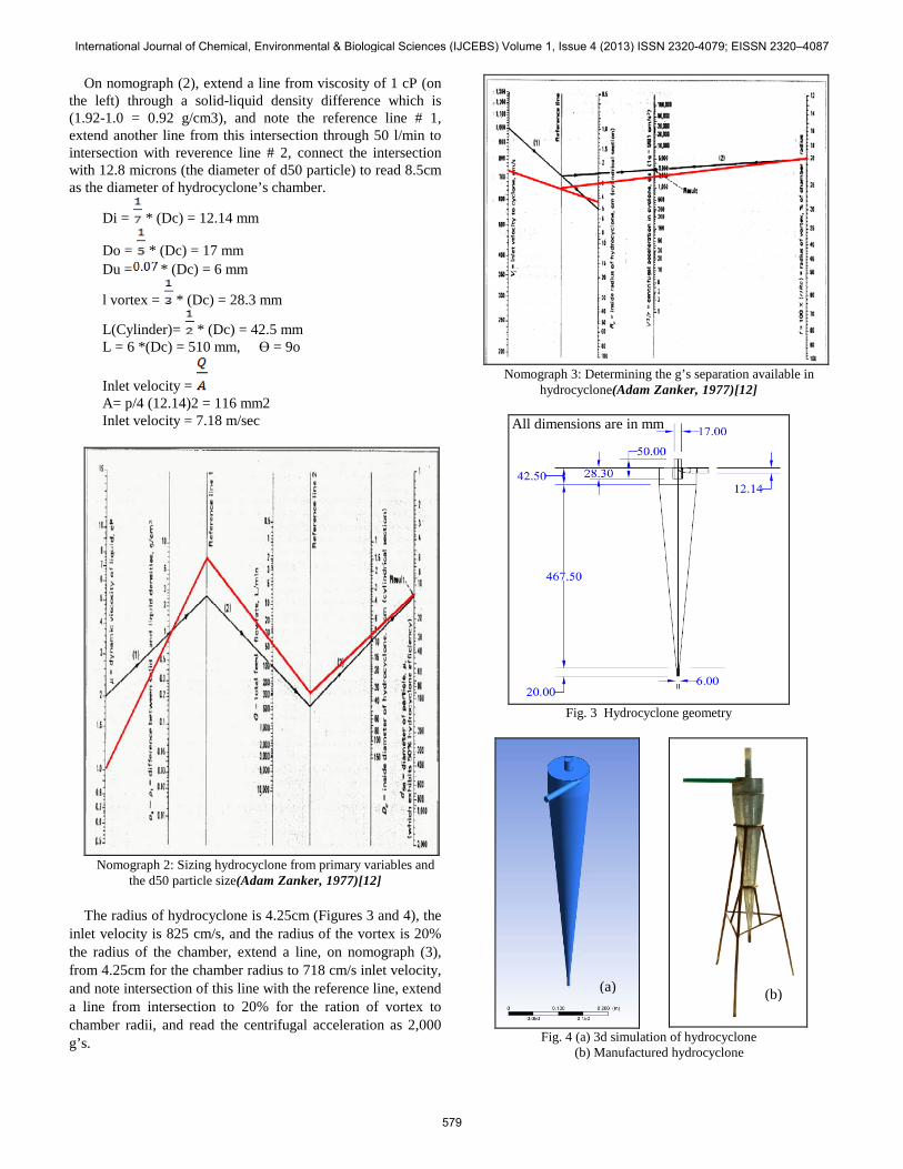
Assume that synthetic raw water has a density of 1.0 g/cm3 and viscosity of 1 cP contains solid particles, and flows at a rate of 50 l/min. the solid particles have a density of 1.920 g/cm3, and a 95% of particles having a diameter of 20 microns should be removed. By using nomograph (1), extending a line from 95% through 20 microns to read 12.8 microns which is the d50 particle size.
Nomograph 1. Determining d50 particle size from the desired
particle separation (Adam Zanker, 1977)[12]
International Journal of Chemical, Environmental & Biological Sciences (IJCEBS) Volume 1, Issue 4 (2013) ISSN 2320-4079; EISSN 2320–4087
578
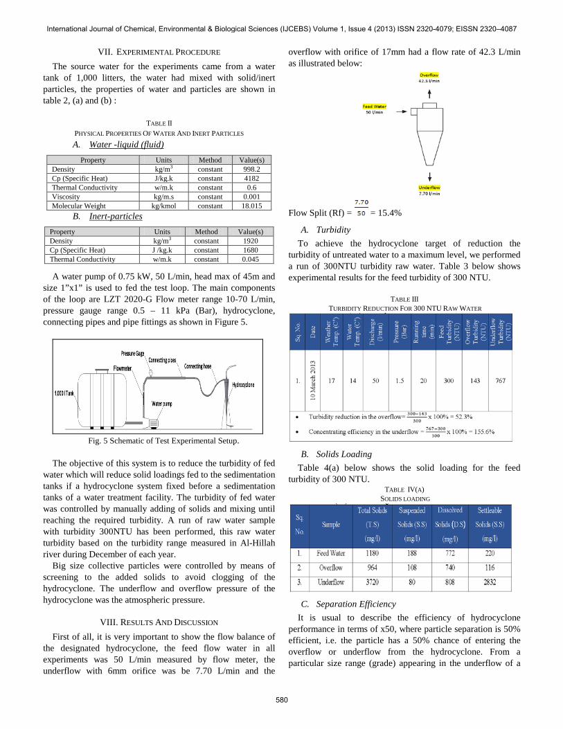
On nomograph (2), extend a line from viscosity of 1 cP (on the left) through a solid-liquid density difference which is (1.92-1.0 = 0.92 g/cm3), and note the reference line # 1, extend another line from this intersection through 50 l/min to intersection with reverence line # 2, connect the intersection with 12.8 microns (the diameter of d50 particle) to read 8.5cm as the diameter of hydrocyclone’s chamber.
Di = * (Dc) = 12.14 mm
Do = * (Dc) = 17 mm Du = * (Dc) = 6 mm
l vortex = * (Dc) = 28.3 mm
L(Cylinder)= * (Dc) = 42.5 mm L = 6 *(Dc) = 510 mm, Ө = 9o
Inlet velocity = A= p/4 (12.14)2 = 116 mm2 Inlet velocity = 7.18 m/sec
Nomograph 2: Sizing hydrocyclone from primary variables and
the d50 particle size(Adam Zanker, 1977)[12] The radius of hydrocyclone is 4.25cm (Figures 3 and 4), the
inlet velocity is 825 cm/s, and the radius of the vortex is 20% the radius of the chamber, extend a line, on nomograph (3), from 4.25cm for the chamber radius to 718 cm/s inlet velocity, and note intersection of this line with the reference line, extend a line from intersection to 20% for the ration of vortex to chamber radii, and read the centrifugal acceleration as 2,000 g’s.
Nomograph 3: Determining the g’s separation available in
hydrocyclone(Adam Zanker, 1977)[12]
Fig. 3 Hydrocyclone geometry
Fig. 4 (a) 3d simulation of hydrocyclone
(b) Manufactured hydrocyclone
(a) (b)
All dimensions are in mm
International Journal of Chemical, Environmental & Biological Sciences (IJCEBS) Volume 1, Issue 4 (2013) ISSN 2320-4079; EISSN 2320–4087
579
VII. EXPERIMENTAL PROCEDURE The source water for the experiments came from a water
tank of 1,000 litters, the water had mixed with solid/inert particles, the properties of water and particles are shown in table 2, (a) and (b) :
TABLE II PHYSICAL PROPERTIES OF WATER AND INERT PARTICLES A. Water -liquid (fluid)
Property Units Method Value(s) Density kg/m3 constant 998.2 Cp (Specific Heat) J/kg.k constant 4182 Thermal Conductivity w/m.k constant 0.6 Viscosity kg/m.s constant 0.001 Molecular Weight kg/kmol constant 18.015
B. Inert-particles Property Units Method Value(s) Density kg/m3 constant 1920 Cp (Specific Heat) J /kg.k constant 1680 Thermal Conductivity w/m.k constant 0.045
A water pump of 0.75 kW, 50 L/min, head max of 45m and size 1”x1” is used to fed the test loop. The main components of the loop are LZT 2020-G Flow meter range 10-70 L/min, pressure gauge range 0.5 – 11 kPa (Bar), hydrocyclone, connecting pipes and pipe fittings as shown in Figure 5.
Fig. 5 Schematic of Test Experimental Setup.
The objective of this system is to reduce the turbidity of fed
water which will reduce solid loadings fed to the sedimentation tanks if a hydrocyclone system fixed before a sedimentation tanks of a water treatment facility. The turbidity of fed water was controlled by manually adding of solids and mixing until reaching the required turbidity. A run of raw water sample with turbidity 300NTU has been performed, this raw water turbidity based on the turbidity range measured in Al-Hillah river during December of each year.
Big size collective particles were controlled by means of screening to the added solids to avoid clogging of the hydrocyclone. The underflow and overflow pressure of the hydrocyclone was the atmospheric pressure.
VIII. RESULTS AND DISCUSSION First of all, it is very important to show the flow balance of
the designated hydrocyclone, the feed flow water in all experiments was 50 L/min measured by flow meter, the underflow with 6mm orifice was be 7.70 L/min and the
overflow with orifice of 17mm had a flow rate of 42.3 L/min as illustrated below:
Flow Split (Rf) = = 15.4%
A. Turbidity To achieve the hydrocyclone target of reduction the
turbidity of untreated water to a maximum level, we performed a run of 300NTU turbidity raw water. Table 3 below shows experimental results for the feed turbidity of 300 NTU.
TABLE III
TURBIDITY REDUCTION FOR 300 NTU RAW WATER
B. Solids Loading
Table 4(a) below shows the solid loading for the feed turbidity of 300 NTU.
TABLE IV(A) SOLIDS LOADING
C. Separation Efficiency
It is usual to describe the efficiency of hydrocyclone performance in terms of x50, where particle separation is 50% efficient, i.e. the particle has a 50% chance of entering the overflow or underflow from the hydrocyclone. From a particular size range (grade) appearing in the underflow of a
International Journal of Chemical, Environmental & Biological Sciences (IJCEBS) Volume 1, Issue 4 (2013) ISSN 2320-4079; EISSN 2320–4087
580
hydrocyclone, grade efficiency can be determined based on its mass in feed as written in equation 6 below:
(6)
Furthermore, a grade efficiency of 100% could be obtained by simply blocking off the overflow, i.e. whilst achieving nothing. The concept of reduced grade efficiency is used to overcome the effect due to flow split. It is assumed that the amount of material entering the underflow without experiencing classification is proportional to the volume flow split going to the underflow.
In general, the reduced grade efficiency Ei* is therefore:
Ei* = Ei - Rf (7)
Where Rf is the volumetric flow split of the underflow relative to the feed. Some consideration of grade efficiency has been made (Bradley, 1965) and the following equation proposed to overcome this effect:
(8) The different grade efficiency curves are illustrated in
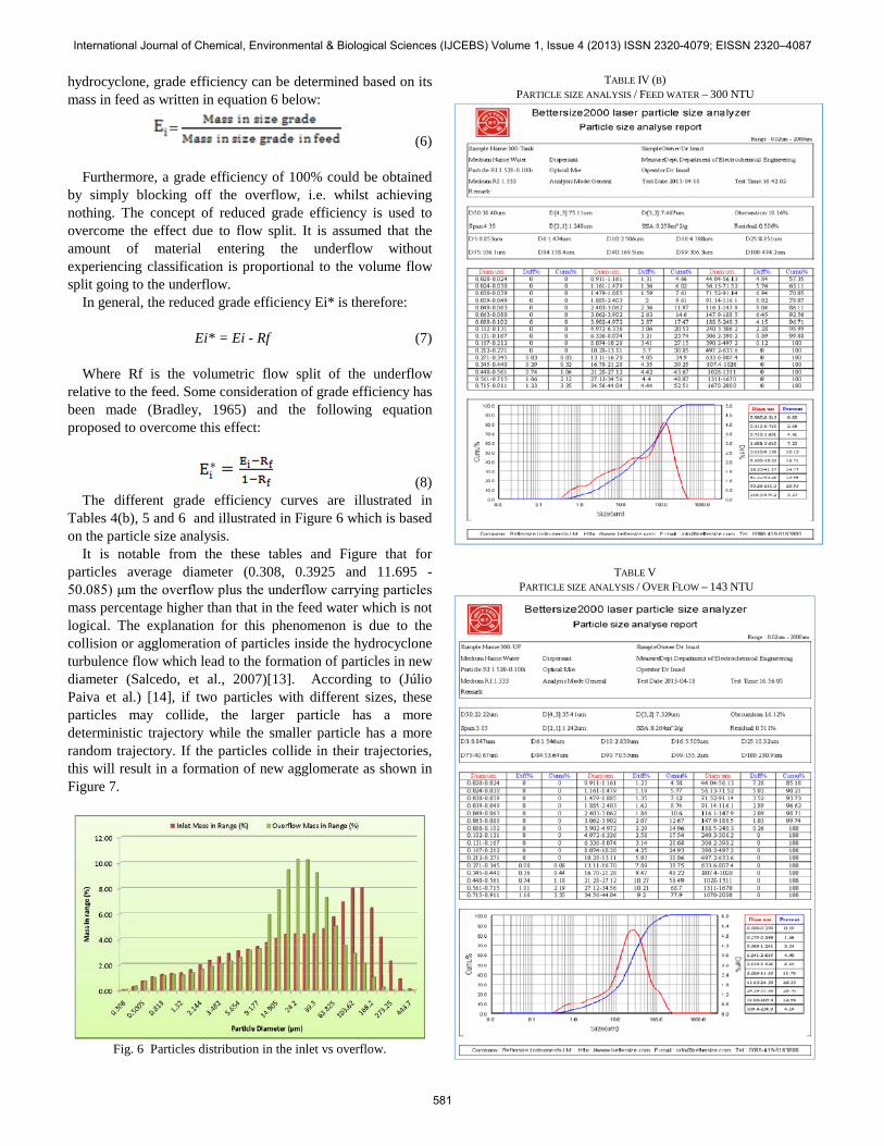
Tables 4(b), 5 and 6 and illustrated in Figure 6 which is based on the particle size analysis.
It is notable from the these tables and Figure that for particles average diameter (0.308, 0.3925 and 11.695 - 50.085) μm the overflow plus the underflow carrying particles mass percentage higher than that in the feed water which is not logical. The explanation for this phenomenon is due to the collision or agglomeration of particles inside the hydrocyclone turbulence flow which lead to the formation of particles in new diameter (Salcedo, et al., 2007)[13]. According to (Júlio Paiva et al.) [14], if two particles with different sizes, these particles may collide, the larger particle has a more deterministic trajectory while the smaller particle has a more random trajectory. If the particles collide in their trajectories, this will result in a formation of new agglomerate as shown in Figure 7.
Fig. 6 Particles distribution in the inlet vs overflow.
TABLE IV (B) PARTICLE SIZE ANALYSIS / FEED WATER – 300 NTU
TABLE V PARTICLE SIZE ANALYSIS / OVER FLOW – 143 NTU
International Journal of Chemical, Environmental & Biological Sciences (IJCEBS) Volume 1, Issue 4 (2013) ISSN 2320-4079; EISSN 2320–4087
581
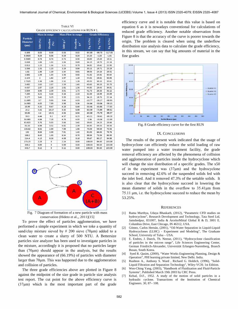
TABLE VI
GRADE EFFICIENCY CALCULATIONS FOR RUN # 1.
Fig. 7 Diagram of formation of a new particle with mass
conservation (Hideto et al.,, 2011)[15] To prove the effect of particles agglomeration, we have
performed a simple experiment in which we toke a quantity of sand/clay mixture sieved by # 200 sieve (70μm) added to a clean water to create a slurry of 500 NTU. A Bettersize particles size analyzer has been used to investigate particles in the mixture, accordingly it is proposed that no particles larger than (70μm) should appear in the analysis, but the results showed the appearance of (66.19%) of particles with diameter larger than 70μm. This was happened due to the agglomeration and collision of particles.
The three grade efficiencies above are plotted in Figure 8 against the midpoint of the size grade in particle size analysis test report. The cut point for the above efficiency curve is (37μm) which is the most important part of the grade
efficiency curve and it is notable that this value is based on equation 6 as it is nowadays conventional for calculations of reduced grade efficiency. Another notable observation from Figure 8 is that the accuracy of the curve is poorer towards the origin. The problem is cleared when using the underflow distribution size analysis data to calculate the grade efficiency, in this stream, we can say that big amounts of material in the fine grades
Fig. 8 Grade efficiency curve for the first RUN
IX. CONCLUSIONS
The results of the present work indicated that the usage of hydrocyclone can efficiently reduce the solid loading of raw water pumped into a water treatment facility, the grade removal efficiency are affected by the phenomena of collision and agglomeration of particles inside the hydrocyclone which will change the size distribution of a specific grades. The x50 of in the experiment was (37μm) and the hydrocyclone succeed in removing 42.6% of the suspended solids fed with the inlet feed. And it removed 47.3% of the settable solids. It is also clear that the hydrocyclone succeed in lowering the mean diameter of solids in the overflow to 35.41μm from 75.11 μm, i.e. the hydrocyclone succeed to reduce the mean by 53.25%.
REFERENCES [1] Rama Murthya, Udaya Bhaskarb, (2012), “Parametric CFD studies on
hydrocyclone”, Research Development and Technology, Tata Steel Ltd, Jamshedpur, 831007, India & ArcelorMittal Global R & D, 3001 E. Columbus Drive, East Chicago, IN 46312, USA.
[2] Gómez, Carlos Hernán, (2001), “Oil-Water Separation in Liquid-Liquid Hydrocyclones (LLHC) - Experiment and Modeling”, The Graduate School, University of Tulsa – USA.
[3] E. Endres, J. Dueck, Th. Neesse, (2011), “Hydrocyclone classification of particles in the micron range”, Life Sciences Engineering Center, German Friedrich-Alexander, Universität Erlangen-Nuremberg, Branch Busan, South Korea.
[4] Syed R. Qasim, (2000), “Water Works Engineering Planning, Design & Operation”, PHI learning private limited, New Delhi. India.
[5] Rushton A., Anthony S. Ward , Richard G. Holdich, (1996), "Solid-Liquid Filtration and Separation Technology", Wiley-VCH; 1st Edition.
[6] Wen-Ching Yang, (2003), "Handbook of Fluidization and Fluid-Particle Systems", Published March 19th 2003 by CRC Press.
[7] Kelsal, D.F., 1952. A study of the motion of solid particles in a hydraulic cyclone. Transactions of the Institution of Chemical Engineers. 30, 87– 108.
International Journal of Chemical, Environmental & Biological Sciences (IJCEBS) Volume 1, Issue 4 (2013) ISSN 2320-4079; EISSN 2320–4087
582
[8] Sang Huck Park, (2003), “Separation of polymer particles using a hydrocyclone”, Lehigh University.
[9] Shojaeefard M. H., Noorpoor A.R., Yarjiabadi H., Habibian M., (2006), “Particle Size Effects on Hydrocyclone Performance”, Automotive Engineering Department, Iran University of Science and Technology. Islamic Republic of Iran.
[10] Bradley, D., (1965), “The Hydrocyclone,” Pergamon Press. [11] Joao Damaceno, (2003), “Differences of behavior between
hydrocyclone with Bradly and Rietema geometries, Federal University of Uberlandia, Brazil.
[12] Adam Zanker, (1977), “Hydrocyclone dimension and performance”, Oil Researches Center Ltd., Haifa, the occupied Palestine.
[13] Salcedo, R. L. R., (2007),” Fine particle capture in biomass boilers with recirculation gas cyclones: Theory and practice”. Powder Technology, pp. 89–98.
[14] Julio Paiva, Romualdo Salcedo, Paulo Araujo, (2010), “Impact of particle agglomeration in cyclones”, Faculty of engineering, University of Porto, Portugal.
[15] Hideto Yoshida , Yuuki Hayase, Kunihiro Fukui, Tetsuya Yamamoto, (2011), “Effect of conical length on separation performance of sub-micron particles by electrical hydro-cyclone”, Department of Chemical Engineering, Hiroshima University, 1-4-1, Kagamiyama Higashi-Hiroshima, Hiroshima, 739-8527, Japan.
International Journal of Chemical, Environmental & Biological Sciences (IJCEBS) Volume 1, Issue 4 (2013) ISSN 2320-4079; EISSN 2320–4087
583