Impressions in extra-oral maxillofacial prosthesis- An ...
8
International Journal of Oral Health Dentistry 2021;7(2):81–88 Content available at: https://www.ipinnovative.com/open-access-journals International Journal of Oral Health Dentistry Journal homepage: www.ijohd.org Review Article Impressions in extra-oral maxillofacial prosthesis- An overview Ornelya Marissa Fernandes 1, *, Suneetha Rao 1 , Prerana E 1 , Anju Anil 1 , Shruti Mishra S 1 , Mohammed Shamil 1 1 Dept. of Prosthodontics, Vydehi Institute of Dental Sciences and Research Centre, Bengaluru, Karnataka, India ARTICLE INFO Article history: Received 08-05-2021 Accepted 24-06-2021 Available online 13-07-2021 Keywords: Nasal prosthesis Auricular prosthesis Ocular prosthesis Orbital prosthesis Cranial prosthesis ABSTRACT The disfigurement caused by loss of any part of the body is often a psychologically damaging experience for the patient. To gain improved fit and intimate tissue adaptation of the prosthesis, an accurate impression and fitting technique is necessary. This article reviews various impression techniques that can be used in clinical practice as and when need arises. © This is an open access article distributed under the terms of the Creative Commons Attribution License (https://creativecommons.org/licenses/by/4.0/) which permits unrestricted use, distribution, and reproduction in any medium, provided the original author and source are credited. 1. Introduction Maxillofacial disfigurement or defects can be congenital, developmental, traumatic or due to ablative surgery. These type of defects compromise the appearance and function, rendering an individual incapable of leading a relatively normal life and thereby affecting his/her psyche. 1 As the quality of life is altered in these patients, social integration becomes difficult and therefore the expectation to return to “normalcy” collapses. 2 In such cases where an anatomical part is lost, microvascular surgical reconstruction by free flaps is usually the treatment of choice. However, anatomic complexity, radiation therapy, possibility of recurrence, procedural complexity, medical condition or personal desires may exclude it as an option. An alternate treatment option in these cases would be prosthetic rehabilitation. 1 The various extra oral defects encountered are-auricular defects, orbital/ocular defects, nasal defects, mid-facial, cranial and defects of hand/fingers. In clinical maxillofacial prosthodontic practice, impression making is the primary or * Corresponding author. E-mail address: [email protected] (O. M. Fernandes). the first and most important procedure. A good impression is invaluable in the fabrication of an aesthetic and functional prosthesis. Hence, there is a need to know the various impression techniques available and incorporate them in clinical practice for patient care. Hence, an overview of the same is presented. 2. Impression for Auricular Prosthesis Fabrication An auricular defect can be caused by several conditions like trauma, congenital malformation, or surgical removal of a neoplasm. 3 The auricular defects maybe unilateral or bilateral. The unilateral defects involve obtaining impressions of both the defect side and unaffected ear. Several impression techniques have been advocated by different authors. 2.1. Reversible hydrocolloid – By Kenneth E Brown (1970) 4 In this technique the patient needs to be placed on a dental chair in a near supine position, after which the head is then rotated so the defect is present on a horizontal plane. https://doi.org/10.18231/j.ijohd.2021.019 2395-4914/© 2021 Innovative Publication, All rights reserved. 81
Transcript of Impressions in extra-oral maxillofacial prosthesis- An ...
International Journal of Oral Health Dentistry 2021;7(2):81–88
Content available at: https://www.ipinnovative.com/open-access-journals
International Journal of Oral Health Dentistry
Journal homepage: www.ijohd.org
Review Article
Impressions in extra-oral maxillofacial prosthesis- An overview
Ornelya Marissa Fernandes1,*, Suneetha Rao1, Prerana E1, Anju Anil1,Shruti Mishra S1, Mohammed Shamil11Dept. of Prosthodontics, Vydehi Institute of Dental Sciences and Research Centre, Bengaluru, Karnataka, India
A R T I C L E I N F O
Article history:Received 08-05-2021Accepted 24-06-2021Available online 13-07-2021
Keywords:Nasal prosthesisAuricular prosthesisOcular prosthesisOrbital prosthesisCranial prosthesis
A B S T R A C T
The disfigurement caused by loss of any part of the body is often a psychologically damaging experiencefor the patient. To gain improved fit and intimate tissue adaptation of the prosthesis, an accurate impressionand fitting technique is necessary. This article reviews various impression techniques that can be used inclinical practice as and when need arises.
© This is an open access article distributed under the terms of the Creative Commons AttributionLicense (https://creativecommons.org/licenses/by/4.0/) which permits unrestricted use, distribution, andreproduction in any medium, provided the original author and source are credited.
1. Introduction
Maxillofacial disfigurement or defects can be congenital,developmental, traumatic or due to ablative surgery. Thesetype of defects compromise the appearance and function,rendering an individual incapable of leading a relativelynormal life and thereby affecting his/her psyche. 1
As the quality of life is altered in these patients,social integration becomes difficult and therefore theexpectation to return to “normalcy” collapses.2 In suchcases where an anatomical part is lost, microvascularsurgical reconstruction by free flaps is usually the treatmentof choice. However, anatomic complexity, radiation therapy,possibility of recurrence, procedural complexity, medicalcondition or personal desires may exclude it as an option.An alternate treatment option in these cases would beprosthetic rehabilitation.1
The various extra oral defects encountered are-auriculardefects, orbital/ocular defects, nasal defects, mid-facial,cranial and defects of hand/fingers. In clinical maxillofacialprosthodontic practice, impression making is the primary or
* Corresponding author.E-mail address: [email protected] (O. M. Fernandes).
the first and most important procedure. A good impressionis invaluable in the fabrication of an aesthetic and functionalprosthesis. Hence, there is a need to know the variousimpression techniques available and incorporate them inclinical practice for patient care. Hence, an overview of thesame is presented.
2. Impression for Auricular Prosthesis Fabrication
An auricular defect can be caused by several conditionslike trauma, congenital malformation, or surgical removalof a neoplasm.3 The auricular defects maybe unilateralor bilateral. The unilateral defects involve obtainingimpressions of both the defect side and unaffected ear.Several impression techniques have been advocated bydifferent authors.
2.1. Reversible hydrocolloid – By Kenneth E Brown(1970)4
In this technique the patient needs to be placed on a dentalchair in a near supine position, after which the head isthen rotated so the defect is present on a horizontal plane.
https://doi.org/10.18231/j.ijohd.2021.0192395-4914/© 2021 Innovative Publication, All rights reserved. 81
82 Fernandes et al. / International Journal of Oral Health Dentistry 2021;7(2):81–88
The area around the ear is then generously outlined withan indelible pencil, and coordinates of the vertical andhorizontal axes of the ear are made on the patient’s skin.These markings are then transferred with the impressionon to the working cast. These coordinates are of valuein obtaining the proper orientation over the defect whilemaking a new ear form. The patient’s skin is then boxedto the circumscribed outline with a collar of wax anda reversible hydrocolloid impression is made by gentlypainting the material over the defect site. The impressionmaterial is then allowed to set and is carefully removed andinspected for accuracy and a working cast is poured.
2.2. Irreversible hydrocolloid-alternate technique-ByMathews MF (2000)5
In this technique, using the unaffected ear as a guide,reference lines are scribed around the defect area. Aface-bow or custom-made orientation caliper can beused in transferring the vertical and horizontal axes ofthe unaffected ear to the restorative site with a skinmarker. These lines will be transferred to the impression.Petroleum jelly or other lubricants are then applied tothe hair and surrounding area and the external auditorymeatus is blocked with a cotton pellet or small sponge.A rigid impression tray (plastic tub with the bottomremoved (Reprosil Putty container; Dentsply InternationalInc, Milford, DE) or a piece of polyvinyl chloride (PVC)tube with 2 to 3 strips of utility rope wax around oneend is used to box the impression site to achieve a sealwithout distorting the area. An adhesive is then applied andirreversible hydrocolloid impression material is then usedin a very fluid consistency. A 60-mL disposable syringeis loaded with the impression material and then injectedunder the helix, providing support with a strip of gauzecovered with the mix. Material is then injected into theinternal contours of the ear and the impression is completed.After the irreversible hydrocolloid has set, it is removedusing a slight twist. (twist clockwise on the right ear,counterclockwise on the left). The impression is then boxedand poured.
2.3. Implant retained auricular prosthesis -John F.Wolfaardt Philip (1996)6
In this technique a preliminary impression is made withimpression copings incorporated in it, followed by which arelative bar and clip retained resin substructure is fabricatedand is placed 1-3 mm away from the skin. Autopolymerisingresin custom tray is then fabricated and is indexed tothe resin substructure. This provides a clear visualizationof retentive bar through the resin substructure througha window in it. The point of maximum skin depressionis determined by assessing the movement of condyle ofmandible under preauricular skin and head movement and
impression is made in these areas. The desired position ofthe prosthesis is then marked on the skin and a disposablesyringe loaded with uncatalyzed silicone putty is thenused to place the material around the margin of acrylicresin substructure to obtain a seal and continuous skincontact. The tray is then painted with an adhesive andloaded with polyether impression material and placed onthe substructure and seated to engage the indices. Therelationship of retentive bar can be verified by viewing theacrylic resin substructure through cutout in the tray. Theimpression is recovered and area of soft tissues with notissue contact are identified and trimmed with a bur. Astainless steel wire of diameter that matches the retentivebar is introduced into the clips in the resin substructure. Theimpression is boxed and poured.
2.4. Implant impression technique – by Bergstrom(1993)7
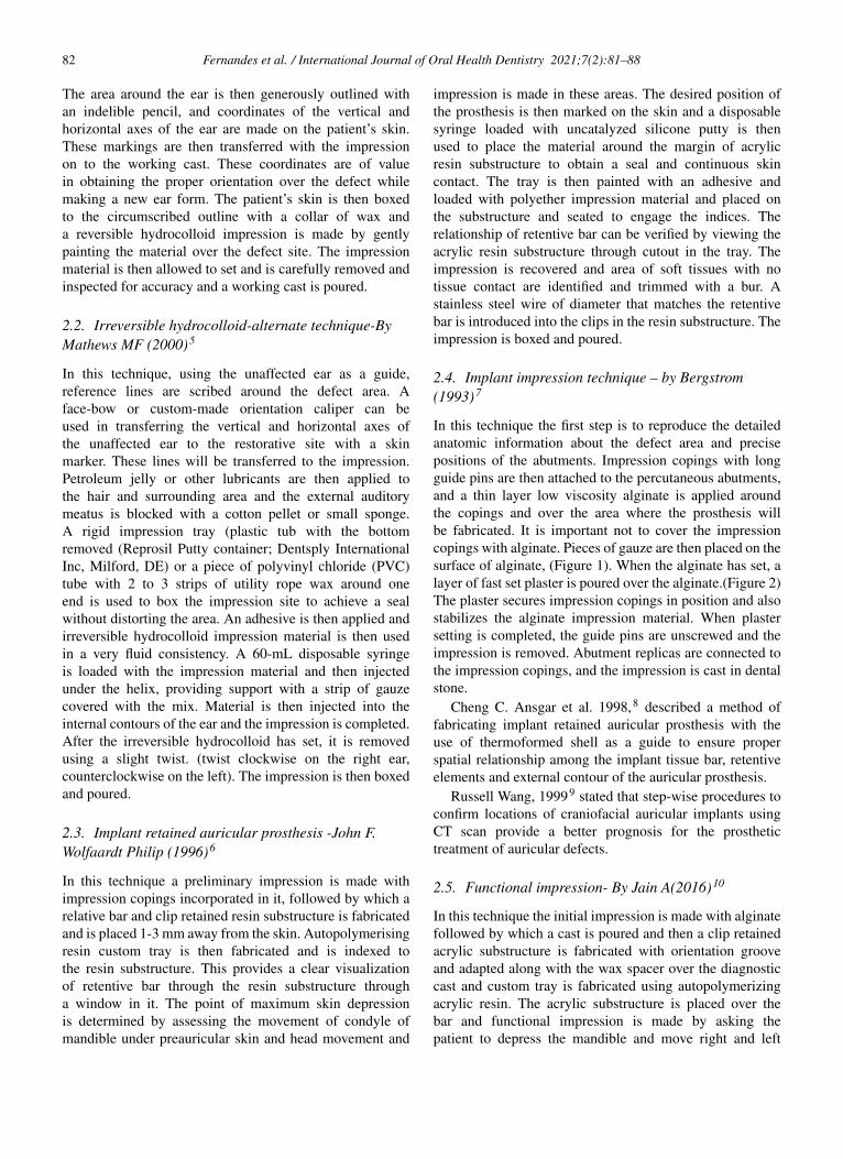
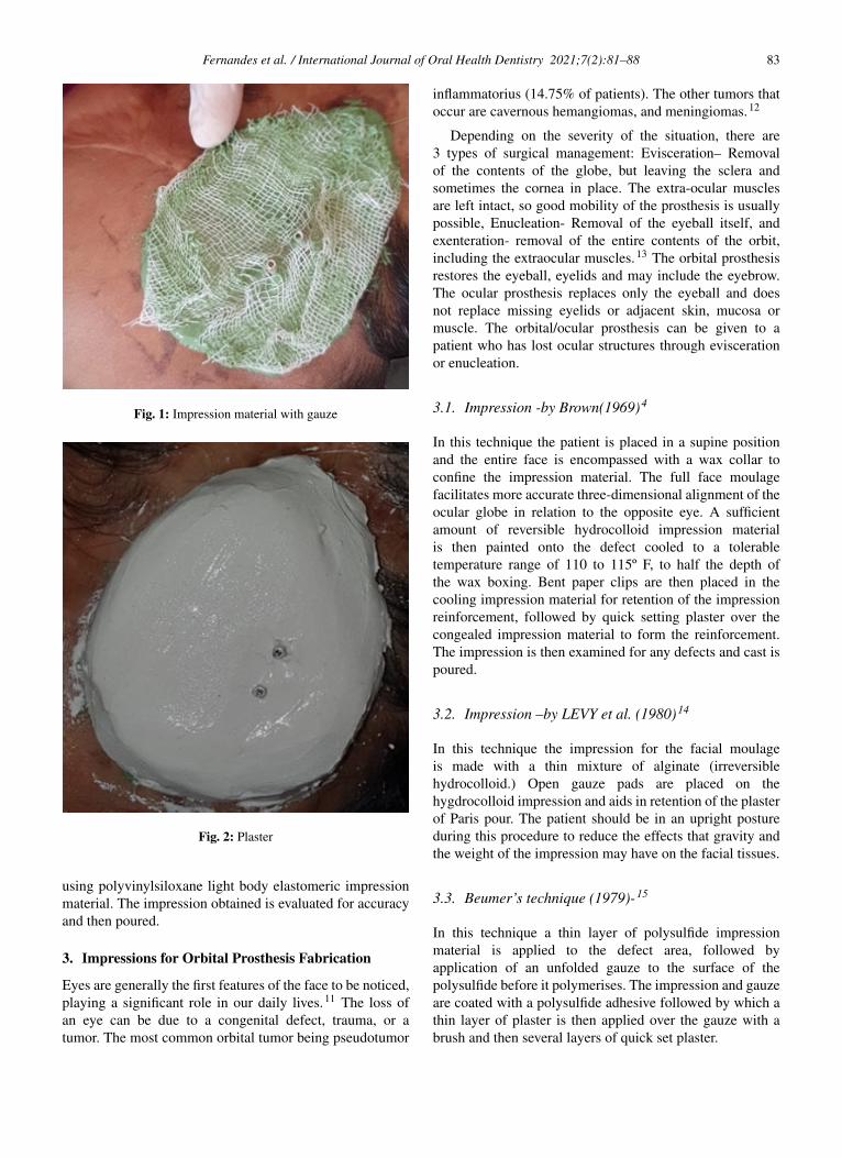
In this technique the first step is to reproduce the detailedanatomic information about the defect area and precisepositions of the abutments. Impression copings with longguide pins are then attached to the percutaneous abutments,and a thin layer low viscosity alginate is applied aroundthe copings and over the area where the prosthesis willbe fabricated. It is important not to cover the impressioncopings with alginate. Pieces of gauze are then placed on thesurface of alginate, (Figure 1). When the alginate has set, alayer of fast set plaster is poured over the alginate.(Figure 2)The plaster secures impression copings in position and alsostabilizes the alginate impression material. When plastersetting is completed, the guide pins are unscrewed and theimpression is removed. Abutment replicas are connected tothe impression copings, and the impression is cast in dentalstone.
Cheng C. Ansgar et al. 1998,8 described a method offabricating implant retained auricular prosthesis with theuse of thermoformed shell as a guide to ensure properspatial relationship among the implant tissue bar, retentiveelements and external contour of the auricular prosthesis.
Russell Wang, 19999 stated that step-wise procedures toconfirm locations of craniofacial auricular implants usingCT scan provide a better prognosis for the prosthetictreatment of auricular defects.
2.5. Functional impression- By Jain A(2016)10
In this technique the initial impression is made with alginatefollowed by which a cast is poured and then a clip retainedacrylic substructure is fabricated with orientation grooveand adapted along with the wax spacer over the diagnosticcast and custom tray is fabricated using autopolymerizingacrylic resin. The acrylic substructure is placed over thebar and functional impression is made by asking thepatient to depress the mandible and move right and left
Fernandes et al. / International Journal of Oral Health Dentistry 2021;7(2):81–88 83
Fig. 1: Impression material with gauze
Fig. 2: Plaster
using polyvinylsiloxane light body elastomeric impressionmaterial. The impression obtained is evaluated for accuracyand then poured.
3. Impressions for Orbital Prosthesis Fabrication
Eyes are generally the first features of the face to be noticed,playing a significant role in our daily lives.11 The loss ofan eye can be due to a congenital defect, trauma, or atumor. The most common orbital tumor being pseudotumor
inflammatorius (14.75% of patients). The other tumors thatoccur are cavernous hemangiomas, and meningiomas.12
Depending on the severity of the situation, there are3 types of surgical management: Evisceration– Removalof the contents of the globe, but leaving the sclera andsometimes the cornea in place. The extra-ocular musclesare left intact, so good mobility of the prosthesis is usuallypossible, Enucleation- Removal of the eyeball itself, andexenteration- removal of the entire contents of the orbit,including the extraocular muscles.13 The orbital prosthesisrestores the eyeball, eyelids and may include the eyebrow.The ocular prosthesis replaces only the eyeball and doesnot replace missing eyelids or adjacent skin, mucosa ormuscle. The orbital/ocular prosthesis can be given to apatient who has lost ocular structures through eviscerationor enucleation.
3.1. Impression -by Brown(1969)4
In this technique the patient is placed in a supine positionand the entire face is encompassed with a wax collar toconfine the impression material. The full face moulagefacilitates more accurate three-dimensional alignment of theocular globe in relation to the opposite eye. A sufficientamount of reversible hydrocolloid impression materialis then painted onto the defect cooled to a tolerabletemperature range of 110 to 115º F, to half the depth ofthe wax boxing. Bent paper clips are then placed in thecooling impression material for retention of the impressionreinforcement, followed by quick setting plaster over thecongealed impression material to form the reinforcement.The impression is then examined for any defects and cast ispoured.
3.2. Impression –by LEVY et al. (1980)14
In this technique the impression for the facial moulageis made with a thin mixture of alginate (irreversiblehydrocolloid.) Open gauze pads are placed on thehygdrocolloid impression and aids in retention of the plasterof Paris pour. The patient should be in an upright postureduring this procedure to reduce the effects that gravity andthe weight of the impression may have on the facial tissues.
3.3. Beumer’s technique (1979)-15
In this technique a thin layer of polysulfide impressionmaterial is applied to the defect area, followed byapplication of an unfolded gauze to the surface of thepolysulfide before it polymerises. The impression and gauzeare coated with a polysulfide adhesive followed by which athin layer of plaster is then applied over the gauze with abrush and then several layers of quick set plaster.
84 Fernandes et al. / International Journal of Oral Health Dentistry 2021;7(2):81–88
3.4. Multiple tray technique for implant-retainedorbital prostheses –by Thomas S16
In this technique after exposure of the implants andplacement of healing cuffs, an irreversible hydrocolloidimpression of the defect is made and cast is poured. On thepreliminary cast, relief wax is placed over the duplicatedimplant healing cuffs to allow adequate space for impressionmaterial. The acrylic resin custom trays are then fabricatedby making two trays triangular in shape and separated fromeach other to separate the defect into superior and inferiorparts. A third middle tray over the other trays are madeand positioned on the cast. The external matrix (fourth)tray is made by lubricating the external surfaces of thethree internal trays on the preliminary cast and to form thematrix over the internal trays. When set, the external matrixtray is removed and perforated with a No. 8 round bur toenhance mechanical retention of the impression material.The tray is removed and polished. Appropriate abutmentsare placed on the implants and fit of the trays for adaptationto the defect is checked. The hair is then lubricated with apetroleum based lubricant. The implant transfer componentsis then placed in position and the tray is painted with anadhesive and allowed to dry. The inferior impression is thenmade by syringing impression material around the implanttransfer parts, in the inferior part of the orbit, and in thetray. The excess material is then removed. The externalaspect of the inferior impression is then lubricated withpetroleum jelly. The superior impression is made in thesame manner. If a middle tray is used, the clearance for thetray is checked. The tray is adjusted and an impression ismade with sufficient impression material to allow joining ofall impressions without locking one tray to the other. Theexternal matrix tray is then adapted over the impressionsto assess fit, painted with adhesive and allow to dry. Withthe impression material at each end, the external matrixtray is seated over the impression trays and allowed toset. The impressions is dissembled in a reverse order. Theappropriate implant transfer analogs are then placed inthe impressions and the impressions are reassembled usingsticky wax to secure them together. The impression is thenpoured and cast is obtained.
4. Impressions for Ocular Prosthesis Fabrication
Ocular maxillofacial prosthesis artificially replaces amissing eye lost as a result of trauma, congenital absenceor surgery; the prosthesis does not replace missing eyelidsor adjacent skin, mucosa or muscle.17 Various ocularimpression have been described in the literature.
4.1. Stock tray impression-by Allen L et al. (1969)18,19
In this impression technique a stock ocular tray is placedinto the defect to determine the proper orientation and fitwithout overextension. The tray is then removed and the
ophthalmic alginate impression material is loaded in thesyringe and sufficient material is ejected to fill the concavityof the tray. The tray is reinserted and adequate materialis injected to elevate the eyelid contours similar to thenormal side. Once filled the patient is directed to move theireyes both up and down and once the impression sets, it isremoved and examined for voids.
4.1.1. Stock ocular tray modifications1. Engelmier R.L.20 advocated autoclavable custom
made metal impression trays to improve infectioncontrol. Stock trays in ticonium which is a nonprecious,removable partial denture alloy (TiconiumCo, Albany, NY) and can be autoclaved for reuse isused with ophthalmic alginate(Ophthalmic Moldite).
2. Maloney 21 ocular tray consists of customized stocktrays with 3 channels through the superior edge toprevent air entrapment and a raised ring around thestem prevents the eyelid from blocking the channels.
3. Sykes, Essop, and Veres 22 used modeling plasticimpression compound as an ocular tray material,forming it around one half of a small rubber balland placing a hollow tube through it. Ophthalmicalginate is then injected through the tube to make theimpression.
4.2. External tray impression-by Taylor T.D(2000)1
In this technique alginate impression material is expressedinto the defect using a disposable syringe. The patientis instructed to stare straight ahead as the material sets.Next a perforated acrylic resin tray is loaded and placedover the defect. The impression is first recovered fromthe lower, shallower sulcus, then rotated out of the deeperupper sulcus. The impression is boxed and poured in thedental stone upto the height of contour of the impression.A separating agent is then placed and the reminder of theimpression is poured.
4.3. Impression with custom ocular tray –by Miller(1996)23
In this technique a solid suction rod is attached to thepatient’s existing prosthesis shell and then invested in analginate mold. The alginate is allowed to set and theprosthesis, conformer, or wax is removed and replaced withclear acrylic resin. Perforations are made in the tray, and atunnel is cut through which alginate impression material isinjected.
4.4. Empirical technique- By Le Grand and Hughes(1990)24
In this technique a wax shell and aluminium iris buttonis taken to determine the anterior portion of the eye. The
Fernandes et al. / International Journal of Oral Health Dentistry 2021;7(2):81–88 85
aluminum button will make handling the shell easier. Oncethe desired shape is obtained, the button is removed and a(premade) plastic tube is attached. Sticky wax may be usedto adhere the tube for extra strength. The tube will thenbe attached to a syringe and enable alginate to flow intothe tray/socket. Once the alginate is set, a two-piece stonemold is made around the impression and shell. Speed andefficiency are two advantages in using this technique.
5. Impressions for Nasal Prosthesis Rehabilitation
A nasal prosthesis re-establishes esthetic form and anatomiccontours, more effectively than by surgical reconstruction asthe nose is a relatively immobile structure.25 Mostly elasticimpression materials that possess good flow properties aresuitable for this task. Block the nasal passage with gauze toprevent entry of impression material.
5.1. Method at UCLA –by Beumer (1979)26
In this technique a thin layer of light body rubber base isapplied to the defect area followed by a layer of gauzeto the rubber base as the material begins to polymerize.Succeeding layers of quick setting plaster are then appliedto the polysulfide to provide support for the elastic material.The initial layer must be thinned and partially set beforesucceeding layers of plaster are added.
5.2. Customized impression technique-by Shetty S(2018)27
In this technique petroleum jelly is applied to the patient’seyebrows and eyelashes and moist gauze is packed toprevent the flow of material into the undesired areas of thedefect. An impression of the defect area is then made usingirreversible hydrocolloid impression material (Tropicalgin,Zhermack, Italy). Paper clips are then attached to the surfaceof the impression material on the face, and dental plasteris applied over it so as to provide a rigid support forthe impression. This impression is then carefully removedand poured using Type III dental stone to obtain a cast.A custom acrylic tray is then fabricated over this cast soas to achieve a functional impression of the tissues. Forthis Polyether (monophase) (Impregum, 3M ESPE, USA)impression material is then carried on the custom tray andthe impression is made by asking the patient to do variousfacial movements ,impression is retrieved and then pouredusing Type III dental stone to obtain a final cast
5.3. Implant-retained nasal prosthesis- by Guttal S28
In this technique after stage two surgery the nasal defectis packed with moist gauze to prevent the flow of theimpression material into the nasal cavity. Care is taken not todistort the nasal tissues while packing the gauze. Impressionposts are then connected to the implants and an impression
is made using medium-body vinylpolysiloxane impressionmaterial (Aquasil, Dentsply, Caulk, Milford, DE) in acustom tray (DPI RR, Mumbai, India). The impression postsare then unthreaded and connected to the laboratory analogs.The master cast is then made with dental stone
6. Impressions for Midfacial Prosthesis Rehabilitation
Midfacial defects are confined to the middle third of theface in the horizontal plane and that communicate withintra-oral maxillary defects. These defects can be classifiedas those in the midline and lateral.29 Midline midfacialdefects include complete or partial involvement of the noseand/or upper lip and communication with an intra-oralmaxillary defect. Lateral midfacial defects include completeor partial involvement of the cheek and orbital contents, andcommunication with an intra-oral maxillary defects.
The defects in this region may result due to certaindisease, pathological changes, radiation, burns, trauma orsurgical intervention. The impression techniques include thefollowing:-
6.1. Impression technique by Metz (1964)30
This technique describes an impression procedure formaxillofacial rehabilitation with facial, nasal and palataldefects. A gauze saturated with petroleum jelly is packedinto the nasal cavity before the maxillary impression ismade. The impression is then taken with an irreversiblehydrocolloid material and casts is poured in dental stone anda denture is fabricated. Followed by this a facial moulageimpression is taken. Eyebrows and exposed hair arelubricated with petroleum jelly. The Negacoll hydrocolloidis thoroughly heated in a double boiler until it becomescreamy and smooth and then brushed on with quick strokes,each slightly overlapping the preceding strokes. The entireface is then covered to a depth of half to one and halfinch.Plaster matrix is then added to a thickness of half inchand gauze is embedded to add strength before it sets. Themoulage is then removed and allowed to harden.
6.2. Impression technique by Victor Matacon et al(1968)31
This a technique for intranasal prosthesis. The patient istipped back in the dental chair and part of the upper lipand external nose is then boxed with wax to confine theimpression material. Alginate impression material is mixedand poured into the boxed area. In order to avoid trapping ofair a small amount of the impression material is placed intothe defect, before pouring the bulk of the material into theboxed area. Paper clips or gauze are then embedded in thesoft irreversible hydrocolloid and the impressions materialis allowed to set. A plaster backing is poured over the clipsto prevent distortion and tearing of the impression, whilstremoving.
86 Fernandes et al. / International Journal of Oral Health Dentistry 2021;7(2):81–88
7. Impressions for Cranial Defect
Defects involving the cranial vault could be a resultof congenital deformities, trauma, decompressivecraniectomies, and/or loss of bone flap due to infection.32,33
Apart from the patient’s physical appearance, a largesurface of the brain remains unprotected. Patients withcranial defects often present with neurological symptomsheadaches, dizziness, irritability, epilepsy, discomfort, andpsychiatric symptoms which are known to improve withrehabilitation.
7.1. Impression technique-by Kharade P (2016)34
Proper examination of the cranial defect needs to be donefirst., following which an impression of the cranial defectis made with irreversible hydrocolloid (Jeltrate Type II;Dentsply Caulk) supported by dental plaster (Kaldent;Kalabhai). The impression is poured in a layered manner toavoid distorting the irreversible hydrocolloid and fabricatethe moulage.
8. Impressions for Hand & Fingers
Finger and partial-finger amputations are frequently themost encountered forms of partial-hand losses. The mostcommon causes of these amputations are traumatic injuries-such as frost bite, gun shot, burns, workers having aprofession of agriculture, fishing, carpentery, congenitalabsences or malformations that present with clinicalchallenges. Any of the fingers may be affected in whole orin part and prosthetic restoration is often difficult. This isparticularly true when multiple fingers are involved
Loss of finger produces significant esthetic andfunctional deficiencies. Common methods to replacethe loss of finger are endoprosthesis (implants) andexoprosthesis(silicon prosthesis, acrylic prosthesis,prosthesis using attachments, and magnets.) Passingthrough various materials, the acceptance rate has beenmuch higher when an individually sculpted customrestoration using silicone elastomer.35,36
8.1. Impression technique-by C.D Clarke (1945)37
In this technique a seamless hand mould is made for theprosthetic hand fabrication by filling a bag with agar. Thehand and arm are inserted and the bag is soaked in ice waterto hasten the setting of the agar. This is a lengthy process.
8.2. Impression technique- by J. Pillet (1983)38
In this technique plaster of Paris is used as a two part mould.This again is a lengthy technique and causes a seam on themodel.
8.3. Defect impression
In this technique the hand is greased very lightly in any hairbearing areas followed by which a cardboard box or 2 litreplastic lemonade bottle is used to contain the impression.The patient is made to stand in a relaxed position with thearm held loosely at the side. The box is then positioned,to check for access. Irreversible hydrocolloid duplicatingmaterial is mixed and then painted all over the impressionarea. The hand is then positioned in the box, which is filledwith a further mix of irreversible hydrocolloid, which inturn is left to set (approximately 10 minutes). When set,the hand is then removed by gently flexing the fingers andintroducing a small amount of water, to break the suction,and withdrawing slowly and the impression is then poured.This same technique can be used for finger impressions
8.4. Impression technique for amputated Finger -byGarg M (2016)39
In this technique a thin layer of petroleum jelly is firstapplied to the patient’s hand prior making an impression.Then a wide plastic container is selected according tothe size of the palm and impressions of affected hand ismade with irreversible hydrocolloid impression material byasking the patient to place his hand into the wide container.The impression is then poured with dental stone to createa positive replica of the amputated finger and associatedstructures.
8.5. Modified impression technique -by Tripathi S(2011)40
This technique requires an impression cap for carryingand supporting the impression material. An impressioncap is used to make the impression with addition siliconeimpression material (Express, 3M ESPE; St. Paul, MN)and then the cast is poured. For the wax pattern of themissing part, an alginate impression of the same fingers ofthe other hand is then made in a slightly flexed positionfor duplicating the natural relaxed posture of the finger. Forretention and also for an easy route for the alginate materiala larger impression cap is used, in which vent holes are made
9. Impression for Toe and Foot Prosthesis
Amputation of entire or part of a limb may be due to variouscauses like systemic or vascular disease, infection, localinjury or trauma.41 Partially amputated lower limbs presenta variety of unique clinical and prosthetic challenges,because of distinctly different amputation levels of the lowerlimb.
9.1. Impression Technique-by Pradeep C (2016)42
In this technique the area is cleaned using aseptictechnique before making the impression. The impression
Fernandes et al. / International Journal of Oral Health Dentistry 2021;7(2):81–88 87
is made using irreversible hydrocolloid. The irreversiblehydrocolloid is mixed as per manufactures instructionsand painted on to the surface of one foot at a time.The irreversible hydrocolloid impression is then coveredby surgical gauze. To reinforce the whole assembly itis then covered with a layer of dental plaster. After thedental plaster had completely set, the impression is removedusing slow rocking movements. Dental stone is poured intoimpression and master cast is obtained free of voids. Theimpression of the unaffected foot serves as a mould to depictthe morphology and aid in the fabrication of the wax pattern.
10. Modern Trends
Until the recent past, conventional impression materialssuch as irreversible hydrocolloid or silicones and techniqueshave been used to fabricate maxillofacial prosthesesand extra-oral radiation devices.43The common problemsrelated with conventional impressions include patientdiscomfort and distortion of the facial soft tissues.44 Thedata can now be obtained with the recent advances like :-
Three-dimensional anatomic data (3-D facialmeasurements) using scanning techniques likecomputerized tomography, magnetic resonance imaging,45
3-D optical scanning, generation of a 3-D Computer Model(Blue-print)46 and manufacturing a physical prototype bycomputer numerically controlled (CNC) milling and Rapidprototyping.44
11. Conclusion
Maxillofacial prosthetic restoration brings about responsesof the whole person. These can be measured indirectlythrough the changes evoked in the self-image and in thestrength of positive optimism. Ultimately, the maxillofacialprostheses restore several types of orofacial defects as wellas improve the patient’s quality of life. This is an ancienttreatment modality that has developed over centuries.The current situation is promising, and there are positiveexpectations for the future.
12. Source of Funding
None.
13. Conflict of Interest
None.
References1. Gupta AD, Verma A, Dubey T, Thakur S. Maxillofacial
prosthetics Part I: A review. Int J Adv Res. 2017;5(9):31–40.doi:10.21474/ijar01/5504.
2. Taylor TD. Clinical Maxillofacial Prosthetics. 1st ed. Illinois:Quintessence Publishing Co. Inc; 2000.
3. Arshad M, Shirani GR, Refoua S. Rehabilitation of an AuricularDefect Using Surgical Stent. World J Plast Surg. 2018;7(1):113–7.
4. Brown KE. Fabrication of orbital prosthesis. Plast Reconstr Surg.1970;45(5):522. doi:10.1097/00006534-197005000-00054.
5. Mathews MF, Sutton AJ, Smith RM. The auricular impression:An alternate technique. J Prosthodont. 2000;9(2):106–9.doi:10.1111/j.1532-849x.2000.00106.x.
6. Wolfaardt JF, Coss P. An impression and cast constructiontechnique for implant-retained auricular prostheses. J Prosthet Dent.1996;75(1):45–9. doi:10.1016/s0022-3913(96)90415-1.
7. Bergstrom K. Prosthetic techniques for orbital defects. Bone anchoredapplications. Goteborg 2:5-8; 1993.
8. Ansgar C, David M, Rony C. Vaccum formed matrix as a guide forthe fabrication of craniofacial implant tissue bar retained auricularprosthesis. J Prosthet Dent. 1998;79(6):711–4.
9. Wang R. Presurgical confirmation of craniofacial implant location inchildren requiring implant retained auricular prosthesis. J ProsthetDent. 1999;81(4):492–5.
10. Jain A, Bhargava A, Sridevi U. Functional impression and castconstruction technique for implant retained auricular prosthesis. DentOral Craniofac Res. 2016;2(3):292–4.
11. Doshi PJ, Aruna B. Prosthetic management of patient with oculardefect. J Indian Prosthod Soc. 2005;5(1):37. doi:10.4103/0972-4052.16340.
12. Markowski J, Kandziora EJ. Primary orbital tumors: A review of 122cases during a 23 year period: A histo-clinical study in material fromthe ENT Department of the Medical university of Silesia. Med SciMonit. 2014;20:988–94.
13. Choubisa D. A simplified approach to rehabilitate an ocular defect:Ocular prosthesis. J Indian Prosthod Soc. 2016;doi:10.4103/0972-4052.179260.
14. Levy M, Schortz RH, Blumenfeld I, Lepley JB. A flexible moulage forthe fabrication of an orbital prosthesis. J Prosthet Dent. 1980;43:436–8. doi:10.1016/0022-3913(80)90217-6.
15. Beumer J, Curtis TA, Firtell DN. Maxillofacial Rehabilitation:Prosthodontic and Surgical Considerations. St. Louis: Mosby; 1979.
16. Thomas KF. Prosthetic rehabilitation. London: Quintessence Pub1Co; 1994. p. 69–98.
17. Glossary of Prosthodontic Terms, Edition Nine. J Prosthet Dent.2017;117(5S):72.
18. Allen L, Bulgarelli DM. Obtaining and understanding the alginateimpression. J Am Soc Occularist. 1988;19:4–13.
19. Allen L, Webster HE. Modified Impression Method of Artificial EyeFitting. Am J Ophthalmol. 1969;67(2):189–218. doi:10.1016/0002-9394(69)93148-1.
20. Engelmier RL. Autoclavable custom made metal impression trays toimprove infection control. J Prosthet Dent. 1987;58:121–2.
21. Maloey BA. Development of impression fitting equipment.A newtechnique. J Am Soc ocularist. 1979;9:32–33.
22. Sykes LM, Essop ARM, Veres EM. Use of custom-made conformersin the treatment of ocular defects. J Prosthet Dent. 1999;82(3):362–5.doi:10.1016/s0022-3913(99)70095-8.
23. Miller BJ. Custom ocular impression trays. J Facial Somato Prosthet.1996;2:109–13.
24. Hughes MO. A fitting tip: wax impression trays. J Ophthal Prosthet.1990;p. 25–7.
25. Jain S, Maru K, Shukla J, Vyas A, Pillai R, Jain P. NasalProsthesis Rehabilitation: A Case Report. J Indian Prosthod Soc.2011;11(4):265–9. doi:10.1007/s13191-011-0094-5.
26. Beumer J, Curtis TA, Firtell DN. Maxillofacial Rehabilitation:Prosthodontic and Surgical Considerations. St. Louis: Mosby; 1979.
27. Kamath J, Shetty S, Mohammed F, Shenoy KK. Nasal reconstructionwith silicone using customised impression technique. J IndianProsthod Soc. 2017;doi:10.4103/jips.jips_82_17.
28. Guttal SS, Patil NP, Thakur S, Kumar S, Kulkarni SS. Implant-Retained Nasal Prosthesis for a Patient Following Partial Rhinectomy:A Clinical Report. J Prosthod. 2009;18(4):353–8. doi:10.1111/j.1532-849x.2008.00422.x.
29. Marunick MT, Harrison R, Beumer J. Prosthodontic rehabilitationof midfacial defects. J Prosthet Dent. 1985;54(4):553–60.doi:10.1016/0022-3913(85)90433-0.
88 Fernandes et al. / International Journal of Oral Health Dentistry 2021;7(2):81–88
30. Metz HH. Maxillofacial prosthetic rehabilitation after mouthand facial surgery. J Prosthet Dent. 1964;14(6):1169–77.doi:10.1016/0022-3913(64)90189-1.
31. Matacon V. Intranasal prosthesis. JProsthet Dent. 1968;19:304–6.32. Bumer J, Curtis TA, Marunick MT. Maxillofacial rehabilitation
prosthodontic and surgical considerations. St Louis: Ishiyaku EuroAmerica; 1996. p. 455–77.
33. Beumer J, Firtell DN, Curtis TA. Current concepts in cranioplasty. JProsthet Dent. 1979;42(1):67–77. doi:10.1016/0022-3913(79)90332-9.
34. Kharade P, Dholam K, Gorakh A. A technique for fabricationof cranial prostheses using high-temperature vulcanizingsilicone material. J Prosthet Dent. 2017;118(1):113–5.doi:10.1016/j.prosdent.2016.10.010.
35. Buckner H. Cosmetic hand prosthesis a case report. J Prosthet Orthot.1980;3:41–5.
36. Kini AY, Byakod PP, Angadi GS, Pai U, Bhandari AJ. ComprehensiveProsthetic Rehabilitation of a Patient with Partial Finger Amputationsusing Silicone Biomaterial. Prosthet Orthot Int. 2010;34(4):488–94.doi:10.3109/03093646.2010.486391.
37. Clarke CD. Seamless prosthetic hands: a technic of fabrication. St.Louis: C. V. Mosby Company; 1945.
38. Pillet J. Esthetic hand prostheses. J Hand Surg. 1983;8(5):778–81.doi:10.1016/s0363-5023(83)80270-6.
39. Garg M, Pathak C, Tangri SB, Gupta A. Prosthetic rehabilitationof an amputated finger. Indian J Dent Sci. 2016;8(3):163–7.doi:10.4103/0976-4003.191734.
40. Tripathi S, Singh RD, Chand P, Mishra N, Yadav LK, SinghSV. A modified approach of impression technique for fabricationof finger prostheses. Prosthet Orthot Int. 2012;36(1):121–4.doi:10.1177/0309364611431480.
41. Maheswari U, Mohamed K, Deora N, Elavia U, Padmanabhan TV.Flexible Cosmetic Silicone Toe and Foot Prostheses in DevelopingCountries—Case Reports. JPO J Prosthet Orthot. 2011;23(4):204–10. doi:10.1097/jpo.0b013e3182349fc5.
42. Dathan PC. Prosthetic Rehabilitation of Lower Limb with RTVSiliconee Using Prosthodontic Clinical and Laboratory Techniques- A Case Report. J Clin Diagn Res. 2016;10(8):35–7.
doi:10.7860/jcdr/2016/19810.8360.43. Mankovich NJ, Samson D, Pratt W, Lew D, Beumer J. Surgical
Planning Using Three-Dimensional Imaging And ComputerModeling. Otolaryngol Clin N Am. 1994;27(5):875–89.doi:10.1016/s0030-6665(20)30614-9.
44. Goyal MK, Goyal S, Dhanasekar B. Modern trends in modelingof extra-oral defects. Indian J Dent Res. 2014;25(1):128–32.doi:10.4103/0970-9290.131170.
45. Penkner K, Santler G, Mayer W, Pierer G, Lorenzoni M.Fabricating auricular prostheses using three-dimensional soft tissuemodels. J Prosthet Dent. 1999;82(4):482–4. doi:10.1016/s0022-3913(99)70038-7.
46. Runte C, Dirksen D, Deleré H, Thomas C, Runte B, Meyer U. Opticaldata acquisition for computer assisted design of facial prostheses. IntJ Prosthodont. 2002;15:129–32.
Author biography
Ornelya Marissa Fernandes, Post Graduate
Suneetha Rao, Professor and HOD
Prerana E, Post Graduate
Anju Anil, Post Graduate
Shruti Mishra S, Senior Lecturer
Mohammed Shamil, Post Graduate
Cite this article: Fernandes OM, Rao S, Prerana E, Anil A, Mishra S S,Shamil M. Impressions in extra-oral maxillofacial prosthesis- Anoverview. Int J Oral Health Dent 2021;7(2):81-88.