Importing Models from Physical Modeling Tools … Models from Physical Modeling Tools Using the FMI...
23
Importing Models from Physical Modeling Tools Using the FMI Standard
Transcript of Importing Models from Physical Modeling Tools … Models from Physical Modeling Tools Using the FMI...
Importing Models from Physical Modeling
Tools Using the FMI Standard

1TESIS DYNAware GmbH, Baierbrunner Str. 15, 81379 Muenchen, Germany, http://www.tesis-dynaware.com/contact All brands, trademarks and registered trademarks are the property of their holders.Copyright © 2014 TESIS DYNAware.
OverviewThe objective of this tutorial is to demonstrate the workflow for the integration of FMUs in DYNA4.
The following use case is explained:
The user has a simulation model from a physical modeling software tool, such as Dymola, AMESim orSimulationX that supports the tool independent Functional Mock-up Interface (FMI) standard.This model (for example a complete drivetrain, combustion engine or electric motor) is to be integratedas a Functional Mock-up Unit (FMU) in the overall model architecture that is a Simulink model with fullDYNA4 integration.The model architecture shown in the tutorial is the one used by DYNA4 models, however the processworks equally well with totally different user-specific model architectures.The FMI Toolbox for MATLAB from Modelon( )http://www.modelon.com/products/fmi-toolbox-for-matlab/is used as the interface to Simulink: Using DLL binaries for FMUs the simulation modes "Normal" and"Accelerator" can be used in Simulink.The simulation may be conducted as a co-simulation or the imported model may be simulated using theSimulink solver.
Tutorial contents:
Exporting Physical Models as FMUs: Describes the process of exporting FMUs from a physicalmodeling tool.Importing FMUs into Simulink: Addresses the necessary setup steps for integrating FMUs into Simulinkusing the FMI Toolbox for MATLAB from Modelon.Importing FMUs into DYNA4: Depicts the required steps to integrate FMUs into a functional DYNA4simulation model based on Simulink.Working with FMUs in DYNA4: Describes options for passing data to FMUs, tracing signals andsimulating FMUs using Simulink and DYNA4.
FMI Toolbox compatibility:
Restrictions regarding the supported physical modeling tools, that can be used for exporting FMUs, canbe found on the Modelon documentation:
.http://www.modelon.com/products/fmi-toolbox-for-matlab/supported-tools/All MATLAB versions from R2007b onwards are supported by the FMI Toolbox for MATLAB. TheUser´s Guide provides further information as to which versions have been tested:http://www.modelon.com/fileadmin/user_upload/Products/Modelon/FMIT/FMIT-1_7/-UsersGuide.pdf.Version 1.7 of the Modelon FMI Toolbox for MATLAB has been tested with DYNA4. All informationprovided in this tutorial is related to this version of the toolbox.
2TESIS DYNAware GmbH, Baierbrunner Str. 15, 81379 Muenchen, Germany, http://www.tesis-dynaware.com/contact All brands, trademarks and registered trademarks are the property of their holders.Copyright © 2014 TESIS DYNAware.
1.
Exporting Physical Models as FMUs
The objective of this tutorial step is to show how to export models from physical simulation
environments as FMUs. The following topics are addressed:
Adjust the simulation model interfaceExport the simulation model as an FMU
Proceed as explained in the following:
Adjust the interface (ports) of your existing simulation model from a physical modeling tool. This must be done in asignal-based way so that the model can be exported as an FMU. This means input and output signals will be requiredto define this interface and it may be necessary to install sensors in order to measure certain model states andactuators in order to apply physical properties to the model.
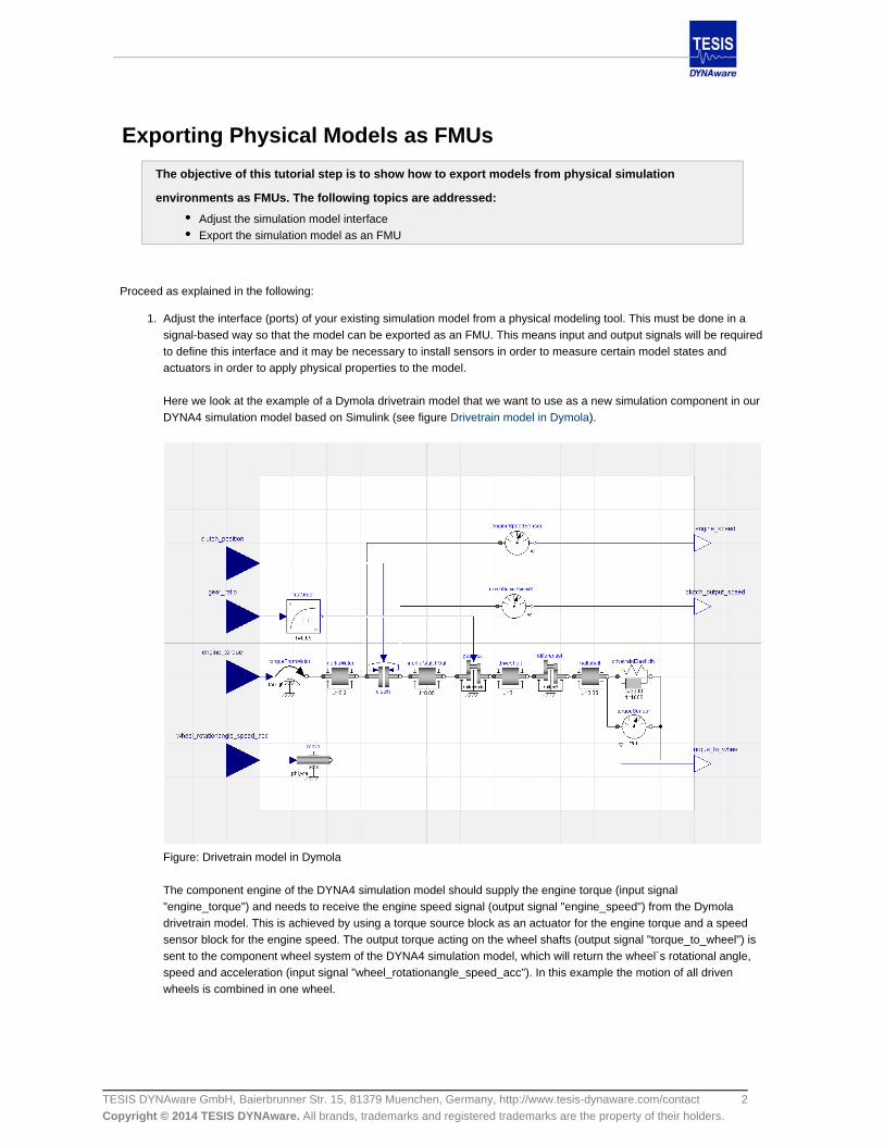
Here we look at the example of a Dymola drivetrain model that we want to use as a new simulation component in ourDYNA4 simulation model based on Simulink (see figure ).Drivetrain model in Dymola
Figure: Drivetrain model in Dymola
The component engine of the DYNA4 simulation model should supply the engine torque (input signal"engine_torque") and needs to receive the engine speed signal (output signal "engine_speed") from the Dymoladrivetrain model. This is achieved by using a torque source block as an actuator for the engine torque and a speedsensor block for the engine speed. The output torque acting on the wheel shafts (output signal "torque_to_wheel") issent to the component wheel system of the DYNA4 simulation model, which will return the wheel´s rotational angle,speed and acceleration (input signal "wheel_rotationangle_speed_acc"). In this example the motion of all drivenwheels is combined in one wheel.

3TESIS DYNAware GmbH, Baierbrunner Str. 15, 81379 Muenchen, Germany, http://www.tesis-dynaware.com/contact All brands, trademarks and registered trademarks are the property of their holders.Copyright © 2014 TESIS DYNAware.
1.
2.
Normally, the Dymola model would work differently to solve the differential equations, but the use of the "move" blockforces the system to use the input signal "wheel_rotationangle_speed_acc" as the rotational motion of the wheel. If forexample the wheel system model was also included within the system boundary of the Dymola model, the interfacesignals woud be different. It is advisable to choose the system boundaries with consideration of the resultingmathematical constraints.
Export the simulation model as an FMU by using the FMI export functionality of your physical simulation tool In Dymola the options for the FMI export can be found in the Simulation Setup GUI (see figure FMI export GUI in
).Dymola
Figure: FMI export GUI in Dymola
There are three settings to be done: Select a , select an FMI and select some further .Type Version Options
As either (FMI-ME) or (FMI-CS) can be selected. Model exchange exportsType Model exchange Co-simulationthe model without solver and Co-simulation exports an encapsulated model and solver.
As select 1.0 to ensure compatability with V1.7 of the Modelon FMI Toolbox. Version
For the it is not necessary to include the source code or store result in mat file.Options

4TESIS DYNAware GmbH, Baierbrunner Str. 15, 81379 Muenchen, Germany, http://www.tesis-dynaware.com/contact All brands, trademarks and registered trademarks are the property of their holders.Copyright © 2014 TESIS DYNAware.
1.
2.
3.
Importing FMUs into Simulink
The objective of this tutorial step is to show how to integrate an FMU into Simulink using the FMI
Toolbox for MATLAB from Modelon. The following topics are addressed:
Install the FMI Toolbox for MATLAB from ModelonAccess the FMU block in Simulink
Proceed as explained in the following:
Install the FMI Toolbox for MATLAB from Modelon and configure the MATLAB installation such that the FMI blocksetlibraries are available. Follow the installation instructions found on the Modelon website: http://www.modelon.com/fileadmin/user_upload/Products/Modelon/FMIT/FMIT-1_7-UsersGuide.pdf
After installing and setup is complete, the FMI Toolbox should appear in the Simulink Library Browser (see figure ). FMI Toolbox in Simulink Library Browser
Figure: FMI Toolbox in Simulink Library Browser
Once this is available, the block can be used in any Simulink model. Drag and drop a copy of the required block into ablank Simulink model (see figure FMU block in Simulink). Either choose the block FMU ME for Model Exchange orFMU CS for Co-simulation.

5TESIS DYNAware GmbH, Baierbrunner Str. 15, 81379 Muenchen, Germany, http://www.tesis-dynaware.com/contact All brands, trademarks and registered trademarks are the property of their holders.Copyright © 2014 TESIS DYNAware.
3.
Figure: FMU Block in Simulink
Double clicking on the block opens a GUI, and the FMU file can be loaded. With the specifications from the loadedFMU file the FMU block automatically adjusts its ports including their names (see figure ). Specified FMU Block in Simulink
Figure: Specified FMU Block in Simulink

6TESIS DYNAware GmbH, Baierbrunner Str. 15, 81379 Muenchen, Germany, http://www.tesis-dynaware.com/contact All brands, trademarks and registered trademarks are the property of their holders.Copyright © 2014 TESIS DYNAware.
1.
2.
3.
4.
Importing FMUs into DYNA4
The objective of this tutorial step is to show how to integrate an FMU into the DYNA4 simulation
framework. The following topics are addressed:
Create a user-defined module including FMU blocks and adjust its settingsCreate a DYNA4 component including FMU modules and import this component into a simulationmodel
The following workflow is recommended because it allows maximum integration with the DYNA4 framework functionality.
The full integration process can be split into four main parts:
Create a user-defined module including FMU blocks.
This module will be saved in the DYNAdatabase, in a user-defined module library. In this way it can be used in anycomponent model in DYNA4.
.Adjust settings of FMU blocks in user-defined modules
Create a DYNA4 component including FMU modules.
This component will be saved in the DYNAdatabase, as a reference DYNA4 component. This allows the user toimport and use the component in any simulation project and any simulation model using the DYNA4 Replacing Model
(for further information see Replacing Model Components in the DYNA4 User Manual) functionality.Components Import an FMU component into a simulation model.
The final step is to import the reference component model from the DYNAdatabase into the desired simulation model.
Notes:
Options regarding the methods of , tips regarding Applying Data to FMU Blocks Tracing Signals of FMU and are discussed in the chapter .Blocks Simulating with FMU Blocks Working with FMUs in DYNA4
Before attempting to import an FMU block, it is helpful to have some understanding of the processes asdescribed in the references, as they are very similar for importing a standard Simulink model withoutthe FMU module.

7TESIS DYNAware GmbH, Baierbrunner Str. 15, 81379 Muenchen, Germany, http://www.tesis-dynaware.com/contact All brands, trademarks and registered trademarks are the property of their holders.Copyright © 2014 TESIS DYNAware.
Creating User-Defined Modules Including FMU Blocks
The objective of this tutorial step is to show how to create a user-defined module including FMU
blocks. The following topics are addressed:
Create a new module in the user-defined library in DYNA4Add an FMU block to this moduleDefine block mask parameters for this module
Proceed as explained in the following:
1. Create a new user-defined module using the Manage Modules wizard (see figure ).Manage Modules page
For detailed information on this topic refer to in the DYNA4 User Manual.Creating a New User-Defined Module
Figure: Manage Modules page
8TESIS DYNAware GmbH, Baierbrunner Str. 15, 81379 Muenchen, Germany, http://www.tesis-dynaware.com/contact All brands, trademarks and registered trademarks are the property of their holders.Copyright © 2014 TESIS DYNAware.
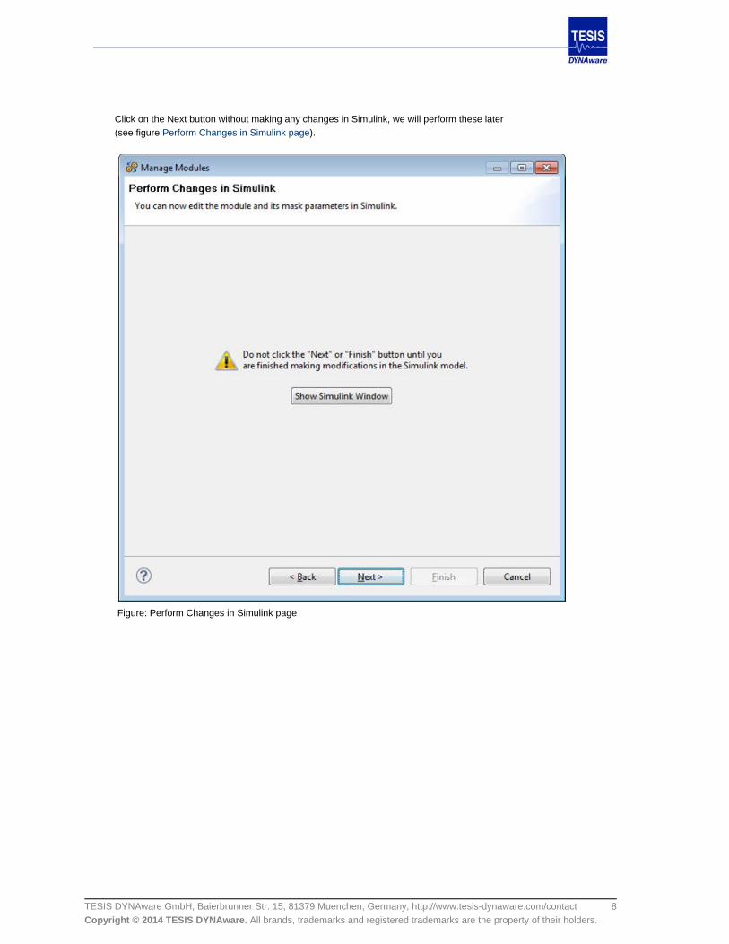
Click on the Next button without making any changes in Simulink, we will perform these later (see figure ). Perform Changes in Simulink page
Figure: Perform Changes in Simulink page

9TESIS DYNAware GmbH, Baierbrunner Str. 15, 81379 Muenchen, Germany, http://www.tesis-dynaware.com/contact All brands, trademarks and registered trademarks are the property of their holders.Copyright © 2014 TESIS DYNAware.
Click on Finish without adding any parameters (see figure ). Edit Module Parameters page
Figure: Edit Module Parameters page Now the wizard has created an empty module and a folder in the DYNAdatabase.

10TESIS DYNAware GmbH, Baierbrunner Str. 15, 81379 Muenchen, Germany, http://www.tesis-dynaware.com/contact All brands, trademarks and registered trademarks are the property of their holders.Copyright © 2014 TESIS DYNAware.
2. Add the .fmu file to the user-defined module library directory (see figure ).User-defined module library directory
Ensure that there are no other copies of the .fmu file on the MATLAB workspace.
Figure: User-defined module library directory
3. Add the FMU block to the user-defined module library and define the Simulink block mask parameters (see figure
Mask editor and edit module parameters page). Therefore switch back to the Manage Modules wizard and follow the instructions in (forEditing a User-Defined Modul
further information about Editing a User-Defined Module see the DYNA4 User Manual) and Importing FMUs into
Simulink. These parameters will then be recognized by the DYNA4 GUI and a corresponding data file template will be
created.
Figure: Mask Editor and Manage Module Parameters page
11TESIS DYNAware GmbH, Baierbrunner Str. 15, 81379 Muenchen, Germany, http://www.tesis-dynaware.com/contact All brands, trademarks and registered trademarks are the property of their holders.Copyright © 2014 TESIS DYNAware.
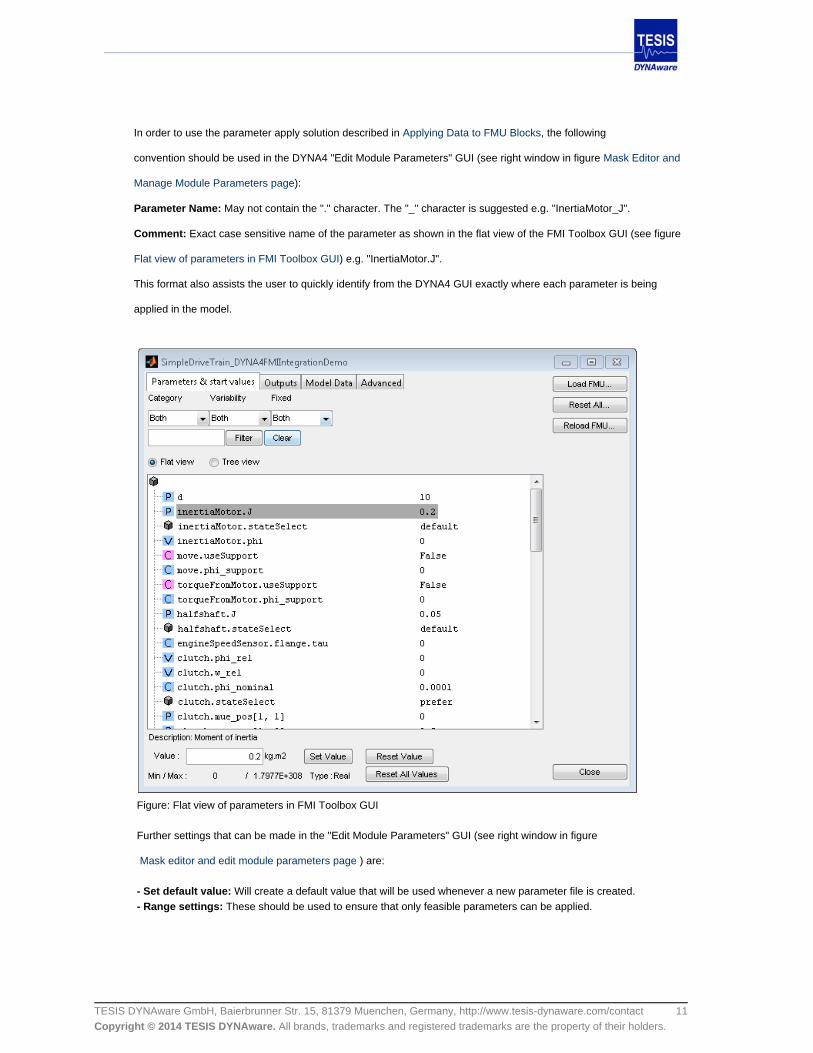
In order to use the parameter apply solution described in , the followingApplying Data to FMU Blocks
convention should be used in the DYNA4 "Edit Module Parameters" GUI (see right window in figure Mask Editor and
Manage Module Parameters page):
Parameter Name: May not contain the "." character. The "_" character is suggested e.g. "InertiaMotor_J".
Comment: Exact case sensitive name of the parameter as shown in the flat view of the FMI Toolbox GUI (see figure
Flat view of parameters in FMI Toolbox GUI) e.g. "InertiaMotor.J".
This format also assists the user to quickly identify from the DYNA4 GUI exactly where each parameter is being
applied in the model.
Figure: Flat view of parameters in FMI Toolbox GUI Further settings that can be made in the "Edit Module Parameters" GUI (see right window in figure
Mask editor and edit module parameters page ) are:
Will create a default value that will be used whenever a new parameter file is created. - Set default value: These should be used to ensure that only feasible parameters can be applied. - Range settings:
12TESIS DYNAware GmbH, Baierbrunner Str. 15, 81379 Muenchen, Germany, http://www.tesis-dynaware.com/contact All brands, trademarks and registered trademarks are the property of their holders.Copyright © 2014 TESIS DYNAware.
Notes:
The DYNA4 Manage Modules wizard automatically creates a set of functions specific to theuser-defined module which are called by the DYNA4 framework when certain events occur. When notrequired, they can be left blank. For further details please refer to Creating a New User-Defined Modulein the DYNA4 User Manual.
13TESIS DYNAware GmbH, Baierbrunner Str. 15, 81379 Muenchen, Germany, http://www.tesis-dynaware.com/contact All brands, trademarks and registered trademarks are the property of their holders.Copyright © 2014 TESIS DYNAware.
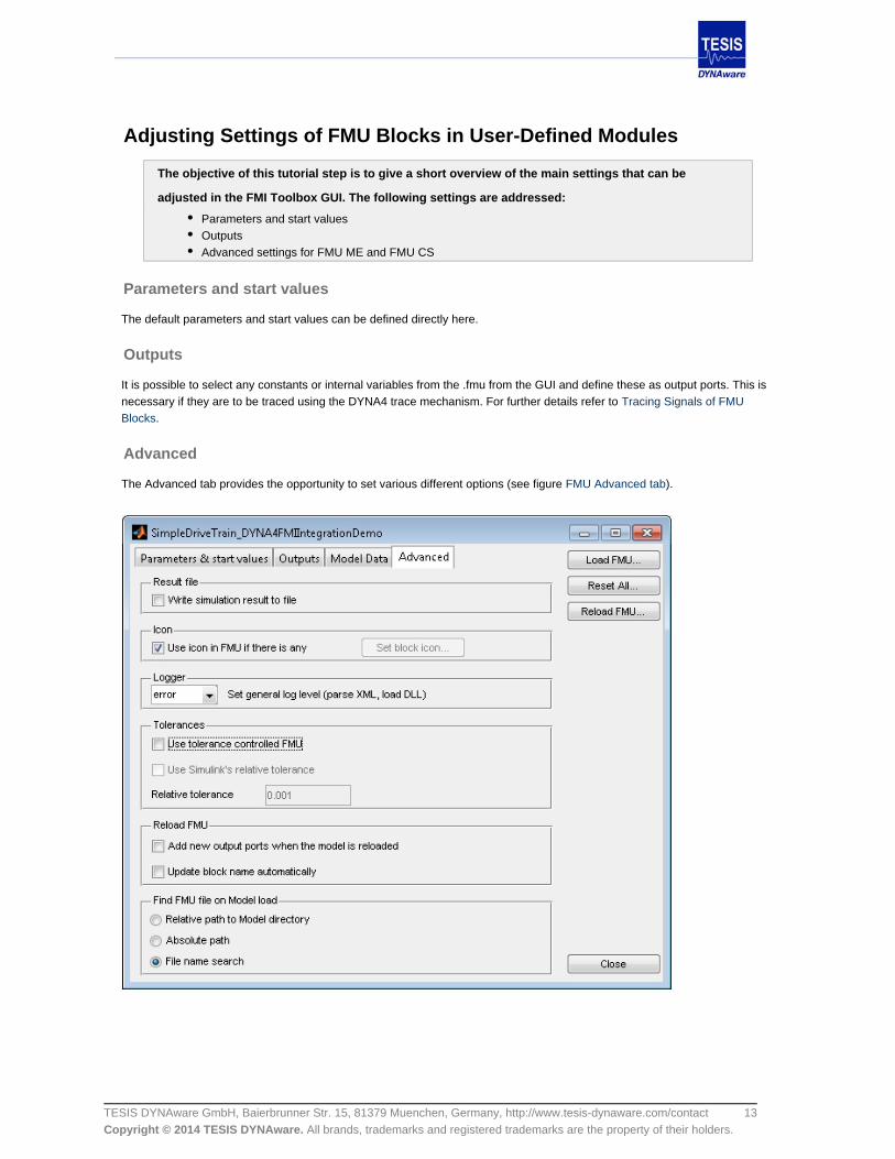
Adjusting Settings of FMU Blocks in User-Defined Modules
The objective of this tutorial step is to give a short overview of the main settings that can be
adjusted in the FMI Toolbox GUI. The following settings are addressed:
Parameters and start valuesOutputsAdvanced settings for FMU ME and FMU CS
Parameters and start values
The default parameters and start values can be defined directly here.
Outputs
It is possible to select any constants or internal variables from the .fmu from the GUI and define these as output ports. This isnecessary if they are to be traced using the DYNA4 trace mechanism. For further details refer to Tracing Signals of FMU
.Blocks
Advanced
The Advanced tab provides the opportunity to set various different options (see figure ).FMU Advanced tab
14TESIS DYNAware GmbH, Baierbrunner Str. 15, 81379 Muenchen, Germany, http://www.tesis-dynaware.com/contact All brands, trademarks and registered trademarks are the property of their holders.Copyright © 2014 TESIS DYNAware.
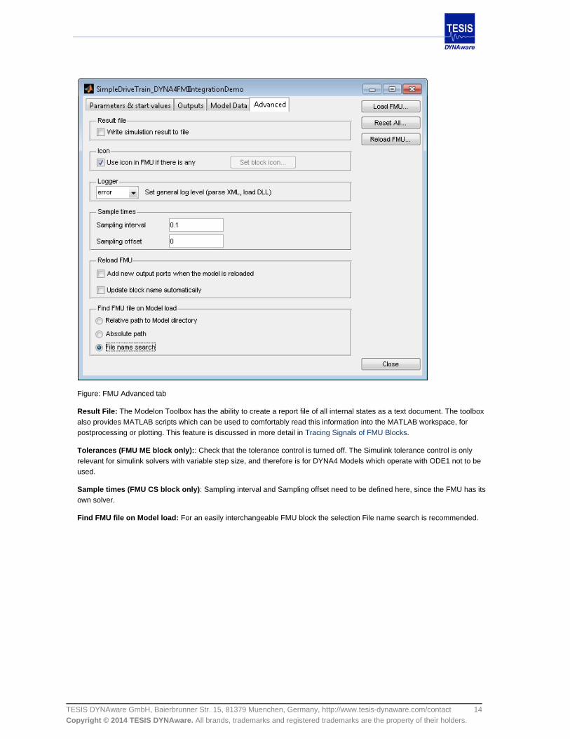
Figure: FMU Advanced tab
Result File: The Modelon Toolbox has the ability to create a report file of all internal states as a text document. The toolboxalso provides MATLAB scripts which can be used to comfortably read this information into the MATLAB workspace, forpostprocessing or plotting. This feature is discussed in more detail in .Tracing Signals of FMU Blocks
Tolerances (FMU ME block only):: Check that the tolerance control is turned off. The Simulink tolerance control is onlyrelevant for simulink solvers with variable step size, and therefore is for DYNA4 Models which operate with ODE1 not to beused.
Sample times (FMU CS block only): Sampling interval and Sampling offset need to be defined here, since the FMU has itsown solver.
Find FMU file on Model load: For an easily interchangeable FMU block the selection File name search is recommended.

15TESIS DYNAware GmbH, Baierbrunner Str. 15, 81379 Muenchen, Germany, http://www.tesis-dynaware.com/contact All brands, trademarks and registered trademarks are the property of their holders.Copyright © 2014 TESIS DYNAware.
1.
2.
Creating DYNA4 Components Including FMU Modules
The objective of this tutorial step is to show how to create a DYNA4 component from a user-defined
FMU module. The following topics are addressed:
Create a new DYNA4 componentIntegrate the user-defined FMU module into this component
Proceed as explained in the following:
Once the user-defined module has been defined the next step is to create a new component. This allows the new component to be directly imported into a simulation model. See in the DYNA4 User Manual for more details on how to create aCreating a New User-Defined Component ModelDYNA4 component in general.
Integrate the user-defined FMU module into the new component (see figure ) and directlyAdd FMU Modules pageconnect it to the rest of your simulation model in Simulink.
Figure: Add FMU Modules page
Notes:
Ignore the following message, should it appear:

16TESIS DYNAware GmbH, Baierbrunner Str. 15, 81379 Muenchen, Germany, http://www.tesis-dynaware.com/contact All brands, trademarks and registered trademarks are the property of their holders.Copyright © 2014 TESIS DYNAware.
1.
2.
Importing FMU Components into Simulation Models
The objective of this tutorial step is to show how to import FMU components into simulation models
in DYNA4. The following topics are addressed:
Import newly created FMU component into the DYNA4 frameworkCreate a module parameter file
Proceed as explained in the following:
As a final step import the newly created FMU component from the DYNAdatabase into the actual simulation model(see figure ). Replace FMU components dialog
For details refer to in the DYNA4 User Manual.Replacing Model Components
Figure: Replace FMU components dialog
Create a module parameter file.
Now that the FMU component and the corresponding user-defined FMU module are included in the active simulationmodel, the data can be applied directly from the DYNA4 framework into the MATLAB workspace.

17TESIS DYNAware GmbH, Baierbrunner Str. 15, 81379 Muenchen, Germany, http://www.tesis-dynaware.com/contact All brands, trademarks and registered trademarks are the property of their holders.Copyright © 2014 TESIS DYNAware.
2.
Once the FMU component has been selected, a parameter file can be created and loaded into the active data set. Ifthe module is new, there will be no existing data file, a new one can be created (see figure ).Create new module parameter file
Figure: Create new module parameter file
The parameters for the model can be entered via the GUI when one double clicks on the desired mfile. Upon savingthe mfile, the parameters for the FMU will be applied to the MATLAB workspace in the MDL structure.
The use of the DYNA4 parameter file is optional and depending on the desired data apply method used, theparameter file may be empty. The options regarding data apply are discussed in more detail in Applying Data to FMU
.Blocks

18TESIS DYNAware GmbH, Baierbrunner Str. 15, 81379 Muenchen, Germany, http://www.tesis-dynaware.com/contact All brands, trademarks and registered trademarks are the property of their holders.Copyright © 2014 TESIS DYNAware.
Working with FMUs in DYNA4
The objective of this tutorial step is to show how to work with FMUs in the DYNA4 simulation
framework after the import steps have been executed successfully. The following topics are
addressed:
Applying Data to FMU Blocks: Depicts options for applying data to the FMU blockTracing Signals of FMU Blocks: Describes options for tracing signals from the FMU blockSimulating with FMU Blocks: Shows tips regarding the simulation of FMUs in the Simulink environmentusing DYNA4

19TESIS DYNAware GmbH, Baierbrunner Str. 15, 81379 Muenchen, Germany, http://www.tesis-dynaware.com/contact All brands, trademarks and registered trademarks are the property of their holders.Copyright © 2014 TESIS DYNAware.
1.
2.
3.
Applying Data to FMU Blocks
The objective of this tutorial step is to show how to apply data to FMU blocks. Following topics are
covered:
How to assign DYNA4 module parameters to FMU block parameters.
Notes on general FMI Toolbox restrictions:
Any tables used as parameters in the FMI model must be of a fixed size. e.g. the parameters may varybut the table dimensions must remain constant.
Once the FMU is part of the active simulation model, it is possible to assign DYNA4 parameters to the the corresponding FMUparameters.
Proceed as explained in the following
Open the DYNA4 module library in Simulink
Select "View Mask" in the module and go to the pane. There you can see all available DYNA4 Module ParametersDYNA4 parameters for this module.
Figure: DYNA4 Module Parameters

20TESIS DYNAware GmbH, Baierbrunner Str. 15, 81379 Muenchen, Germany, http://www.tesis-dynaware.com/contact All brands, trademarks and registered trademarks are the property of their holders.Copyright © 2014 TESIS DYNAware.
2.
3.
4.
5.
6.
Open the (double click on the FMU block) and go to the "Parameters & start values" pane.FMU Edit Mask
Figure: FMU Edit Mask
For each FMU parameter you want to change in DYNA4: Enter the corresponding DYNA4 parameter name in theValue field in the FMU edit mask and press „Set Value“.
Notes:
It is important to add a suffix to the DYNA4 parameter name as this specifies the used.vparameter value structure element. ( see )Figure FMU edit mask
Close the FMU edit mask.
Save the DYNA4 module library.
From now on the selected DYNA4 module parameters are automatically assigned to the corresponding FMU parametersduring the DYNA4 apply procedure.

21TESIS DYNAware GmbH, Baierbrunner Str. 15, 81379 Muenchen, Germany, http://www.tesis-dynaware.com/contact All brands, trademarks and registered trademarks are the property of their holders.Copyright © 2014 TESIS DYNAware.
Tracing Signals of FMU Blocks
The objective of this tutorial step is to show different options how to trace signals of an FMU block
in DYNA4. The following topics are addressed:
Using the DYNA4 trace mechanismUsing the FMI Toolbox report generation function
DYNA4 trace mechanism
It is possible to record individual signals or complete Simulink buses using the DYNA4 Trace mechanism. For further detailsplease refer to Recording a User-Defined Simulink Signal and in the DYNA4 UserRecording a complete Simulink BusManual.
This workflow requires that all desired signals are defined as outputs from the FMU block. For further details on how to specifyadditional outputs for the FMU block please refer to http://www.modelon.com/fileadmin/user_upload/Products/Modelon/FMIT/
.FMIT-1_7-UsersGuide.pdf
Trace functionality of the FMI Toolbox for MATLAB
The alternative is to use the trace functionality of the FMI Toolbox, which traces the internal signals in the FMU and creates aseperate result file.
The result file can then be processed using MATLAB functions from the Modelon FMI Toolbox. For further details please referto .http://www.modelon.com/fileadmin/user_upload/Products/Modelon/FMIT/FMIT-1_7-UsersGuide.pdf
It is also possible to integrate these results into a DYNA4 and combine them with the trace resultspostprocessing functionprovided by DYNA4. Fur further information on how to integrate user functions into the DYNA4 task concept please refer to Us
in the DYNA4 User Manual.ing a Function Node
22TESIS DYNAware GmbH, Baierbrunner Str. 15, 81379 Muenchen, Germany, http://www.tesis-dynaware.com/contact All brands, trademarks and registered trademarks are the property of their holders.Copyright © 2014 TESIS DYNAware.
Simulating with FMU Blocks
Some general notes regarding simulation with the FMU block and DYNA4:
FMI provides a standardized format which allows the easy transfer of models between tools. It shouldhowever be considered that numerical problems can arise if this integration is not done in the mostappropriate manner. This applies of course generally for the simulation of FMUs in Simulink, and is notlimited specifically to DYNA4 models.
Most DYNA4 models are (currently) restricted to operate with the ODE1 Solver in Simulink. Thereforeuse of the FMU block for Model Exchange (FMU ME) is restricted to this solver which means that novariable step size solver or higher order solvers are supported.
The use of the ODE1 solver may not be an appropriate choice for some complex physical models. Itmay be necessary to use a very small step size in order to achieve good results, at the cost ofperformance.
Using the FMU block for Co-simulation (FMU CS) removes this restriction on the solver type for theFMU. When exported in the CS format, the FMU will use its own solver, which is to be defined when theFMU is exported.
Simulating with an FMU model that has been exported in the CS Format requires that the hostcomputer has access to a license from the exporting tool.
Using the FMI Toolbox for Matlab from Modelon and only providing DLL binaries for the FMU, only thesimulation modes "Normal" and "Accelerator" can be used in Simulink.