IMPORTANT SAFETY INSTRUCTIONS - costco.com all packing materials. 4. ... not be allowed to...
19
® Range Hood Pro Pyramid 30 in. and 36 in. User Manual & Installation Instructions IMPORTANT SAFETY INSTRUCTIONS Carefully read the important information regarding installation, safety and maintenance. Keep these instructions for future reference. MAAN1137-06 2017-10-13
Transcript of IMPORTANT SAFETY INSTRUCTIONS - costco.com all packing materials. 4. ... not be allowed to...

® Range HoodPro Pyramid 30 in. and
36 in.
User Manual&
Installation InstructionsIMPORTANT SAFETY INSTRUCTIONS
Carefully read the important information regarding installation, safety and maintenance.
Keep these instructions for future reference. MAAN1137-062017-10-13

— 2 —
INSTALLERS - Start HereSafety Instructions are on pages 4 and 5 and Installation Instructions are on pages 6 to 16. Please perform these steps:1. Read the safety instructions.2. Read all instructions in the Installation section of
this manual BEFORE installing the range hood.3. Remove all packing materials.4. When finished, make sure to leave these instructions with the consumer.5. Installation is to be done by a qualified technician only. However, the
ultimate responsibility for proper installation falls to the owner.6. Product failure due to improper installation is not covered under the Warranty.
CONSUMERS - Start HereSafety Instructions are on pages 4 and 5 and Operating Instructions are on pages 17 and 18.Please perform these steps:1. Read the safety instructions.2. Read all instructions in the manual BEFORE
operating the range hood.3. Remove all packing materials.4. Installation is to be done by a qualified technician only. However, the
ultimate responsibility for proper installation falls to the owner.5. Product failure due to improper installation is not covered under the Warranty.
Before You Begin
Hardware Note: For safety reasons, range hood mounting screws and anchors will not be included due to the variation of cabinetry constructions and wall material. Please consult your installation specialist regarding the optimal type of mounting screws and wall anchors to suit your home’s construction.

— 3 —
Before You Begin ............................................................................................................................... 2
Table of Contents .............................................................................................................................. 3
Important Safety Information ............................................................................................................ 4
Included Parts ................................................................................................................................... 6
Range Hood Dimensions .................................................................................................................. 7
Specifications .................................................................................................................................... 7
Installation ......................................................................................................................................... 8
Step 1 - Read the Safety Instructions ............................................................................................ 8
Step 2 - Unpack Range Hood and Prepare Tools .......................................................................... 8
Step 3 - Plan Desired Location ...................................................................................................... 8
Step 4 - Test Unit Functions .......................................................................................................... 8
Step 5 - Venting Installation Guidelines ......................................................................................... 9
Step 6 - Prepare Motor Housing .................................................................................................. 10
Step 7 - Insert Motor Body Into Main Housing ............................................................................ 10
Step 8 - Attach Motor Body to Main Housing ............................................................................. 11
Step 9 - Join the Connectors ....................................................................................................... 11
Step 10 - Mark Placement of Range Hood Mounting Screws ..................................................... 11
Step 11 - Mount Range Hood Onto Wall ..................................................................................... 12
Step 12 - Install Damper .............................................................................................................. 12
Step 13 - Connect Ductwork ....................................................................................................... 12
Step 14 - Connect to AC.............................................................................................................. 12
Step 15 - Install Lower Chimney .................................................................................................. 13
Step 16 - Install Upper Chimney Bracket .................................................................................... 14
Step 17 - Install Upper Chimney .................................................................................................. 14
Step 18 - Install Grease Trays ...................................................................................................... 15
Step 19 - Install Baffle Filters ....................................................................................................... 15
Operation ........................................................................................................................................ 16
Using the Fan ............................................................................................................................... 16
Using the Time Delay Function .................................................................................................... 16
Turning the Light On or Off........................................................................................................... 16
Maintenance.................................................................................................................................... 17
Replacing the Light Bulbs ............................................................................................................ 17
Cleaning the Range Hood ............................................................................................................ 17
Replacement Parts .......................................................................................................................... 18
Table of Contents

— 4 —
Important Safety Information
• Theinstallationinthismanualisintendedfor qualified installers, service technicians orpersons with a similar qualified background.Installation must be done by qualifiedprofessionals and in accordance with allapplicable codes and standards, includingfire-rated construction.
• The range hood may have very sharpedges; please wear protective gloves if it isnecessary to remove any parts for installing,cleaning or servicing.
• Activating any switch to ON position beforecompleting installation may cause damage orelectric shock.
• Duetothesizeofthisrangehood,atwoperson installation is recommended.
To reduce the risk of fire, electric shock, or injury to persons:
• Forgeneralventilatinguseonly.DO NOT usetoexhausthazardousorexplosivematerialsand vapors.
• WARNING: To Reduce The Risk Of Fire OrElectric Shock, Do Not Use This Fan With AnySolid-State Speed Control Device.
• Thecombustionairflowneededforsafeoperation of fuel-burning equipment may beaffected by this unit’s operation. Follow theheating equipment manufacturer’s guidelineand safety standards such as those publishedby the National Fire Protection Association(NFPA), and the American Society of Heating,Refrigeration and Air Conditioning Engineers(ASHRAE), and other local code authorities.
• Beforeservicingorcleaningtheunit,switchpower off at service panel and lock the service
disconnecting means to prevent power from being switched on accidentally. When the service disconnecting means cannot be locked, securely fasten a prominent warning device, such as a tag, to the service panel.
• Cleangrease-ladensurfacesfrequently.Tooptimizeperformanceandtodisperseairproperly, make sure to vent air outside. DONOT vent exhaust into spaces between walls,crawl spaces, ceilings, attics or garages.
• Ducted fans MUST always be vented tothe outdoors.
• ThisunitMUSTbegroundedandusedwithmetal ductwork only.
• Sufficientairisneededforpropercombustionand exhausting of gases through the duct toprevent back drafting.
• Whencuttingordrillingintowallorceiling,becareful not to damage electrical wiring or otherhidden utilities.
• Allelectricalwiringmustbeproperlyinstalled,insulated and grounded.
• Old ductwork should be cleaned or replacedif necessary to avoid the possibility of agrease fire.
• Check all joints on ductwork to ensureproper connection; all joints should beproperly taped using a certified aluminumor foil tape.
• Usethisunitonlyinthemannerintendedby the manufacturer. If you have questions,contact the vendor.
READ AND SAVE THESE INSTRUCTIONS
READ ALL INSTRUCTIONS BEFORE USE
Read and follow all instructions before using the range hood to prevent the risk of fire, electric shock, personal injury, or damage when using the range hood or appliances with the range hood. This guide does not cover all possible conditions that may occur. Always contact your service technician or manufacturer about problems that you do not understand.

— 5 —
Important Safety Information
WARNING: TO REDUCE RISK OF A RANGE TOP GREASE FIRE:
a) Never leave surface units unattended at highsettings. Boilovers cause smoking and greasyspillovers that may ignite. Heat oils slowly onlow or medium settings.
b) Always turn range hood ON when cooking athigh heat or when flambéing food (i.e. CrepesSuzette,CherriesJubilee,etc.).
c) Clean ventilating fans frequently. Grease shouldnot be allowed to accumulate on fan or filter.Before servicing or cleaning unit, unplug anddisconnect the hood from the power supply.
d) Useproperpansize.Alwaysusecookwareappropriateforthesizeofthesurfaceelement.
WARNING: TO REDUCE RISK OF INJURY TO PERSONS IN THE EVENT OF A RANGE TOP GREASE FIRE, OBSERVE THE FOLLOWING *
a) SMOTHER FLAMES with a close-fittinglid, cookie sheet, or metal tray, then turnoff the burner. BE CAREFUL TO PREVENTBURNS. If the flames do not go outimmediately, EVACUATE AND CALL THEFIRE DEPARTMENT.
b) NEVER PICK UP A FLAMING PAN - You maybe burned.
c) DO NOT USE WATER, including wet dishclothsor towels - a violent steam explosion will result.
d) Use an extinguisher ONLY if:
1) You know you have a Class A, B, Cextinguisher, and you already know how to operate it.
2) The fire is small and contained in the areawhere it is started.
3) The fire department is being called.
4) You can fight the fire with your back to an exit.
* Based on “Kitchen Fire Safety Tips”published by NFPA
To reduce the risk of injury to persons in the event of a gas leaks:
• Extinguishanyopenflame.
• DO NOT turn on the lights or any type of appliance.
• Openalldoorsandwindowstodispersethegas. If you still smell gas, call the gas companyand fire department.
Your safety and the safety of others is very important. We have provided many important safety messages in this manual and on your appliance. Always read and obey all safety messages. All safety messages outline any potentialhazards,howtoreducethechanceofinjury, and possible risks if the instructions are not followed.
READ AND SAVE THESE INSTRUCTIONS

— 6 —
Included Parts
Main Housing Metal damper
Baffle Filters x 2
Upper Chimney
Motor Body
Lower Chimney
Grease Trays x 2
Upper Chimney Bracket
Hardware Note: For safety reasons, range hood mounting screws and anchors will not be included due to the variation of cabinetry constructions and wall material. Please consult your installation specialist regarding the optimal type of mounting screws and wall anchors to suit your home’s construction.
10 x Main Housing Screws 4 x Damper Screws
2 x Upper Chimney Screws
4 x Handle Screws
4 x Split washers
4 x Handles

— 7 —
Range Hood Dimensions
29-7/8” / 35-3/8”(760 mm / 900 mm)
20-1/4”(515 mm)
9-5/
8”(2
45 m
m)
19” t
o 3
7-3/
4”(4
83 m
m t
o 9
58 m
m)
3-1/2”(90 mm)
15-5/8”(397 mm)
13-9/16”(345 mm)
Specifications
Body Design Stainless Steel
Power Rating 120V/60Hz(cETLusCertified)
Total Input Power 406 W
Motor Input Power 400 W
Amperage 3.40 A
Fan 775 CFM
Speed Control Levels 4 Speeds + Booster
Interference Protection Radio Frequency Interference ProtectedNoise Level Low Speed : 44 dB
Motors Single Motor
Control Electronic Slide Touch Panel
Filtration Stainless Steel Baffle Filters
Illumination 2 x 3 W LED
VentingSize Outer 7.3” (185mm), Inner 6.7” (170mm)

— 8 —
Installation
STEP 1Read the Safety Instructions• It is very important to read the safety instructions on pages 4 and 5.
IMPORTANT: It is the installer’s responsibility to comply with installation clearances.
STEP 2Unpack Range Hood and Prepare Tools• Carefully unpack the range hood and parts. Make sure all parts are included as shown on page 6.
• DO NOT remove the protective film covering the appliance until the installation is fully completed.
• Consult a qualified and trained installer or check local codes for makeup air requirement, if any.
STEP 3Plan Desired Location• Plan a desirable location that fits all requirements in the Safety and Installation sections of this manual. Plan where
and how the ductwork will be installed.
• A straight or short duct run will allow the unit to perform most efficiently. Long duct runs, elbows and transitionswillreducetheperformanceoftheunit.Eachelbowisequivalentto5to10feetofstraightrun.Propersizeductwork should be 7” (178 mm) in diameter.
• To reach a 9 foot ceiling make sure hood is installed 30 inches from cooking surface. If you have a ceilinggreater than 9ft, please visit anconahome.com to order a chimney extension.
• If ductwork is already installed: ensure ductwork is free from debris and measures 7” (178 mm) (1” reducers may beused but more than 1” will overwork the motor and the unit will not function properly).
STEP 4Test Unit Functions• Plug the unit in and test all of the functions before installing.
WARNINGS:• PleasemakesuretoreadALLsafetyinstuctionsonpages4and5.• Usetwoormorepeopletomoveandinstallrangehood.• Failuretofollowtheseinstructionscanresultinseriousinjury.
• This unit's damper is located 28" (712 mm) from bottom of range hood, therefore rear venting requires ahigher wall aperture for duct than standard. Please calculate position for duct on wall BEFORE installingthis product (See Height and Clearance illustration on page 9).
• Only one flange is needed in the air duct system, either on top of the motor (provided) or outside.

Wall duct aperture is 28” (711 mm) from bottom of range hood
— 9 —
Installation
STEP 5Venting Installation Guidelines• The following steps are for exterior ventilation.
Height and Clearance
IMPORTANT:• Vent system must terminate to the outside (roof or side wall).• DONOT terminate the vent system in an attic or other
enclosed area.• DONOTuse4”(10.2cm)laundry-typewallcaps.• Usemetal/aluminumventonly.Arigidmetal/aluminum
vent is recommended.• DONOTuseaplasticvent.• Alwayskeeptheductcleantoensureproperairflow.• Calculatethefollowingfiguresbeforeinstallation:
1. Distance from the floor to the ceiling2. Distance between the floor and the countertop/stove3. A distance of 24” to 30” is recommended betweenstove top and the bottom of range hood. 30” minimum is required for gas stove tops.4. Height of hood and duct cover.
For the most efficient & quiet operation:• It isrecommendedthattherangehoodbevented
vertically through the roof through 7 in. (178 mm)or bigger round metal/aluminum vent work.
• Thesizeoftheventshouldbeuniform.• Usenomorethanthree90°elbows.• Make sure there is a minimum of 24” (61 cm) of
straight vent between the elbows if more than oneelbow is used.
• DONOTinstalltwoelbowstogether.• The length of vent system and number of elbows should be
kept to a minimum to provide efficient performance.• Theventsystemmusthaveadamper.Ifrooforwall
cap has a damper, you may remove damper flaps fromdamper to increase air flow.
• Use silver tape or duct tape to seal all joints in thevent system.
• Use caulking to seal exterior wall or roof openingaround the cap.
24” (610 mm) Min / 30” (762 mm) Max
To reach 9 ft ceiling, make sure range hood is installed at least 30” (762 mm) from cooking surface.
28” (711 mm)

— 10 —
Installation
STEP 7Insert Motor Body into Main Housing• Place the main housing over the motor body as shown below.
• Ensure the motor door and black controls on front panel of range hood are facing upwards.
• Fit the top edge of motor body (A) into the main housing.
• Next fit the bottom edge of motor body (B) into the main housing.
STEP 6Prepare Motor Body• Place the motor body on the edge of a flat surface, such as the corner of a table.
• To protect the flat surface from scratches, place the first square piece of styrofoam that you see when the motor bodybox is opened, on the flat surface.
Front View
Motor door
Foam
Table
A
B

— 11 —
Installation
STEP 10Mark Placement of Range Hood Mounting Screws• Use a pencil to mark on the wall the desired placement of the range hood mounting screws.
• Screw two wood screws (not provided) into wall.
• Leave approximately 1/4” (6.3 mm) of the screw head protruding from the wall to allow clearance for mounting therange hood.
• Use threaded drywall anchors when mounting the range hood onto sheet rock. Mounting the hood into wall studs orlumbars is highly recommended.
2-3/8” (60 mm)
1” (25 mm) 1” (25 mm) 2-3/8” (60 mm)
15” (381 mm)
STEP 8Attach Motor Body to Main Housing• Align the 3 screw holes on the bottom edge of the Motor Body with the 3 holes on the bottom edge of the Main
Housing.
• Then align the remaining 9 screw holes and screw together the two pieces using the screws provided.
STEP 9Join the Connectors• Join together the quick connectors at the back of the
main housing and motor body.

— 12 —
STEP 11Mount Range Hood Onto Wall• Position the range hood’s mounting key holes securely onto the range hood mounting screws.
• Finish screwing in the screws until they cannot tighten any further.
STEP 12Install Damper• Place the damper over the ventilation hole on top of the motor body.
• Secure using the four screws (included).
STEP 13Connect Ductwork• Attach ductwork to damper. Secure the ductwork with duct tape to make sure joints are secure and air- tight.
• Do not install the duct tape too tightly as this may prevent the damper flaps from opening which will overwork the motor and cause improper functioning of the unit.
• Fasten all connections with sheet metal screws and tape all joints with certified aluminum or foil tape. Use caulking toseal exterior wall or roof opening around the cap.
STEP 14Connect to AC• ConnectACplugintoagroundedACoutlethaving120V,60Hz.Placetheoutletatamaximumdistanceof33-1/2”
(851 mm) from where the cord exits on the hood.
• SEE IMPORTANT INSTRUCTIONS ON THEFOLLOWING PAGE. 3-Pronged Plug
Ground Plug
3-Prong Receptacle

— 13 —
Installation
IMPORTANT:• Observeallgoverningcodesandordinances.
• It is the customer’s responsibility to contact a qualified electrical installer.• Ifcodespermitandaseparategroundwireisused,itisrecommendedthataqualifiedelectriciandeterminethat
thegroundpathisadequate.A120-Volt,60Hz,AC-only,fusedelectricalsupplyisrequiredonaseparate15-ampcircuit, fused on both sides of the line.
• DONOTgroundtoagaspipe.
• Checkwithaqualifiedelectricianifyouarenotsurethattherangehoodisproperlygrounded.
• DONOThaveafuseintheneutralorgroundcircuit.
IMPORTANT: Save this Installation Guide for electrical inspector’s use.
GROUNDING INSTRUCTIONS:• Thisappliancemustbegrounded.Intheeventofanelectricalshort-circuit,groundingreducestheriskofelectric
shock by providing an escape wire for the electric current.
• Thisapplianceisequippedwithacordhavingagroundingwirewithagroundingplug.Theplugmustbepluggedinto an outlet that is properly installed and grounded.
WARNING: Improper grounding can result in a risk of electric shock.
• Consultaqualifiedelectricianifthegroundinginstructionsarenotcompletelyunderstood,orifdoubtexistsastowhether the appliance is properly grounded. DO NOT use an extension cord. If the power supply cord is too short,have a qualified electrician install an outlet near the appliance.
STEP 15Install Lower Chimney• Place lower chimney on top of the main housing.

— 14 —
Installation
STEP 16Install Upper Chimney Bracket • Position the upper chimney bracket onto the wall
directly below the ceiling. Align the upper chimneybracket with the range hood below.
• Use a pencil to mark desired placement of the upperchimney bracket on the wall.
• Use two wood screws (not provided), and screw theupper chimney bracket into the wall.
• Use threaded drywall anchors when mountingthe bracket onto sheet rock. Mounting the upperchimney bracket into wall studs or lumbars is highlyrecommended.
STEP 17Install Upper Chimney• Remove the protective film from the upper chimney.
Carefully slide the upper chimney inside the lowerchimney.
• Extend the telescopic upper chimney until it reachesthe upper chimney bracket and attach the upperchimney to the bracket using the provided screws.
• Peel off protective film from the rest of the range hood.
15-1/2” (393 mm)
9-3/4” (247 mm)2-3/4” (70 mm) 2-3/4” (70 mm)
Align the upper chimney bracket with the range hood below.

— 15 —
Installation
STEP 19Install Baffle Filters• Hold the baffle filter by the two knobs.
• Place the front of the baffle against the interiorfront of the range hood.
• Slide it up and push the rear of the filter backuntil it sits securely.
• The baffle filters channel grease releasedby cooking foods into the grease trays andprevent flaming foods on the cook top fromdamaging the inside of the range hood. Forthis reason, the baffle filters must ALWAYS beinstalled during range hood use.
• The baffle filters and grease trays should becleaned once a month, or as needed. Seepage 18 for cleaning instructions.
STEP 18Install Grease Trays• Place the grease trays into the the track at the
back of the range hood.
• Slide them left and right until all trays are placedside-by-side in the track.
• The baffle filters and grease trays should becleaned once a month, or as needed. Seepage 18 for cleaning instructions.

— 16 —
Using the Fan
u Press the button to turn the unit on.
v Press the button to turn on the fan.
w Touch the sensor bar to select any of the 4 speeds desired.
x Slide finger at the last two segments to activate Booster mode and to increase motor power for 2.5 minutes. During this time, the segments will flash.
u To set the Time Delay
Function, press the timer button and slide your finger from left to right along the sensor bar to select the desired time period. Time will increase by 5-minute segments to a maximum of 50 minutes. The timer button will flicker once the Time Delay Function has been activated.
v Press the button to turn the fan off.
Turning the Light On or Off
u Press the button to turn the range hood on.
v Press the button to turn the light on.
w Press the button again to turn the light off.
Operation
Using the Time Delay Function

— 17 —
u Unplug the unit from the AC outlet.
v Remove five screws from the light panel, then remove the light bulbs by popping them out.
w Disconnect the light clip.
x Reverse the removal procedures to install the new light bulbs and plug the unit back in.
Be sure electrical power is off and all surfaces are cool before cleaning or servicing any part of the hood.
Range Hood Body• Do not use a steel wool pad; it will scratch the surface.
• To clean the stainless steel surface, use warm soapywater or a stainless steel cleaner. Closely follow thecleanser label instructions. DO NOT use corrosive orabrasive detergents, ammonia products, abrasives oroven cleaners. Always wipe the surface in the direction of the grain.
Baffle Filters and Grease Trays• The saturation of greasy residue in the fan and filters
may cause increased inflammability. Keep unit clean and free of grease and residue build-up at all times to prevent possible fires.
• Baffle filters and grease trays can be cleaned in astandard dishwasher or by using a mild cleaner. DO NOT use corrosive or abrasive detergents, ammonia products, or oven cleaners.
• To remove, first drain and wipe all excess grease witha dry paper towel. Grasp the baffle filter knobs and pullthem up, forward and out. Grasp the grease trays andcarefully lift them up and out of the hood track.
Maintenance
Replacing the Light Bulbs Cleaning the Range Hood
• When cleaning is completed, replace the grease traysand baffle filters as shown in Step 18 and Step 19.
— 18 —
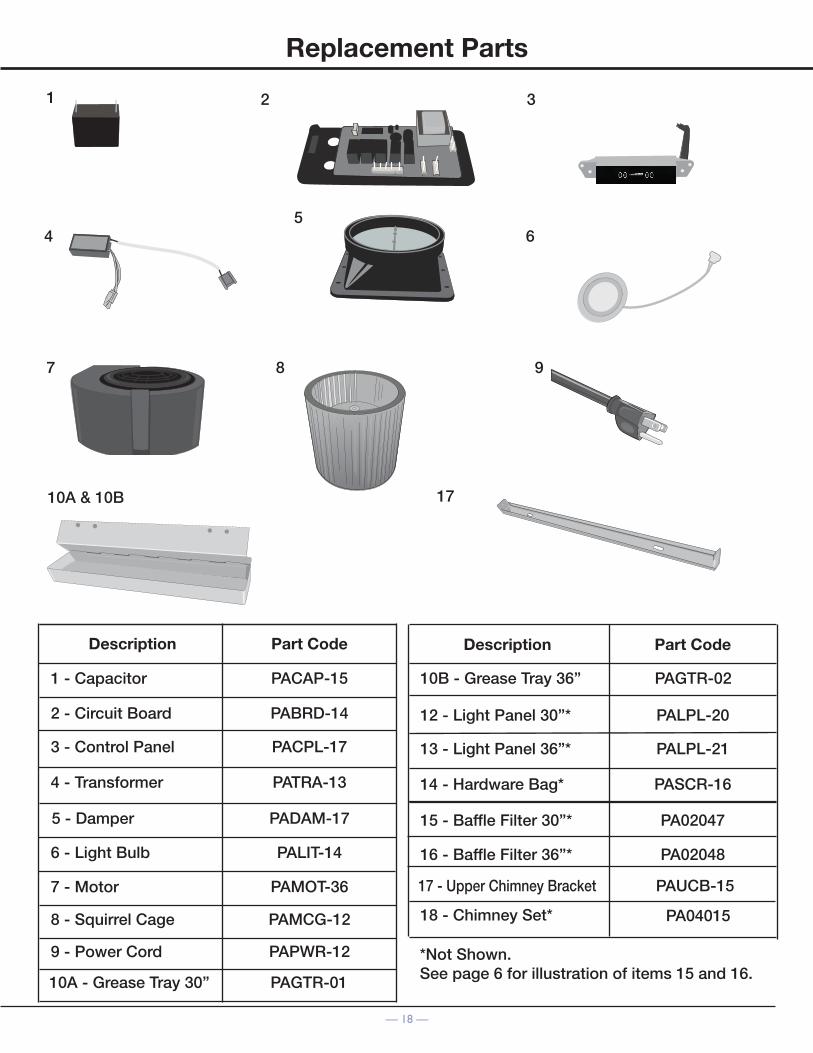
Replacement Parts
87
1
4 6
32
9
10A & 10B 17
PACAP-15
PABRD-14
PACPL-17
PATRA-13
PALIT-14
PADAM-17
PAMOT-36
PAMCG-12
PAPWR-12
1 - Capacitor
2 - Circuit Board
3 - Control Panel
4 - Transformer
6 - Light Bulb
5 - Damper
7 - Motor
8 - Squirrel Cage
9 - Power Cord
Part CodeDescription
10A - Grease Tray 30”
*Not Shown.See page 6 for illustration of items 15 and 16.
PALPL-20
PALPL-21
PASCR-16
12 - Light Panel 30”*
13 - Light Panel 36”*
14 - Hardware Bag*
16 - Baffle Filter 36”*
18 - Chimney Set*
17 - Upper Chimney Bracket
15 - Baffle Filter 30”*
Part CodeDescription
PA02047
PA02048
PAUCB-15
PA04015
PAGTR-01
10B - Grease Tray 36” PAGTR-02
5

© 2017 Copyright of Ancona Home. All rights reserved. This material may not be reproduced, displayed, modified or distributed.
— 19 —
Please register your product warranty by visiting the Ancona Home website.
Canada & USAPhone: 1-800-350-4562
Fax: 800-350-8563Email: [email protected] Website: www.anconahome.com
Ancona is in association with Mr Appliance for all after sales service calls.Please contact their service provider or visit their website:
Phone: 888-998-2011Website: www.mrappliance.com
MAAN1137-06