IMPLEMENTING USB COMMUNICATION EVICE LASS · PDF filecan be an issue for the developer who...
30
Rev. 0.1 3/13 Copyright © 2013 by Silicon Laboratories AN758 AN758 I MPLEMENTING USB C OMMUNICATION D EVICE C LASS (CDC) ON SiM3U1 XX MCU S 1. Introduction USB revolutionized the PC peripheral space by making a very simple plug-and-play interface for users. As a result, many modern computers no longer support RS-232 serial COM ports, opting for the slimmer USB alternative. This can be an issue for the developer who needs a COM port for communication between a peripheral and host PC. A subset of the USB Communication Device Class (CDC) can be used to emulate a serial port providing a virtual COM port UART interface. This allows developers to use legacy applications with new products using the same COM port interface as before, with few hardware and software modifications. Figure 1. USB CDC Virtual COM Port System This application note describes the USB communications device class driver (or USB CDC) in detail and includes an implementation example for the Silicon Labs SiM3U1xx MCU. 1.1. Assumptions This document assumes the following: A working knowledge of the C programming language. Familiarity with the USB 2.0 specification and terms and abbreviations defined by the USB specification. Familiarity with Silicon Labs SiM3U1xx development environment. 1.2. Features and Limitations The CDC firmware implemented with this application note includes the following features: Emulates a serial COM port on PC that supports the CDC Abstract Control Model (ACM). Provides an abstract communication interface for data transfers between the host and the device. Handles standard Chapter 9 USB device requests. Handles CDC-specific requests from USB host. Notifies the USB host of status using an interrupt endpoint. Provides data communication with the USB host using a bulk endpoint. The following baud rates are supported: 1200, 2400, 4800, 9600, 19200, 38400, 57600, 115200, 230400, 460800, and 921600 bps. The example does not implement the following: No CTS/RTS control is performed, so flow control must be set to none in the terminal program. RTS/DTR control is not implemented. Serial Device Host PC USB cable SiM3U1xx RS232 cable End device
Transcript of IMPLEMENTING USB COMMUNICATION EVICE LASS · PDF filecan be an issue for the developer who...

Rev. 0.1 3/13 Copyright © 2013 by Silicon Laboratories AN758
AN758
IMPLEMENTING USB COMMUNICATION DEVICE CLASS (CDC) ON SiM3U1XX MCUS
1. Introduction
USB revolutionized the PC peripheral space by making a very simple plug-and-play interface for users. As a result,many modern computers no longer support RS-232 serial COM ports, opting for the slimmer USB alternative. Thiscan be an issue for the developer who needs a COM port for communication between a peripheral and host PC. Asubset of the USB Communication Device Class (CDC) can be used to emulate a serial port providing a virtualCOM port UART interface. This allows developers to use legacy applications with new products using the sameCOM port interface as before, with few hardware and software modifications.
Figure 1. USB CDC Virtual COM Port System
This application note describes the USB communications device class driver (or USB CDC) in detail and includesan implementation example for the Silicon Labs SiM3U1xx MCU.
1.1. AssumptionsThis document assumes the following:
A working knowledge of the C programming language.
Familiarity with the USB 2.0 specification and terms and abbreviations defined by the USB specification.
Familiarity with Silicon Labs SiM3U1xx development environment.
1.2. Features and LimitationsThe CDC firmware implemented with this application note includes the following features:
Emulates a serial COM port on PC that supports the CDC Abstract Control Model (ACM).
Provides an abstract communication interface for data transfers between the host and the device.
Handles standard Chapter 9 USB device requests.
Handles CDC-specific requests from USB host.
Notifies the USB host of status using an interrupt endpoint.
Provides data communication with the USB host using a bulk endpoint.
The following baud rates are supported: 1200, 2400, 4800, 9600, 19200, 38400, 57600, 115200, 230400, 460800, and 921600 bps.
The example does not implement the following:
No CTS/RTS control is performed, so flow control must be set to none in the terminal program.
RTS/DTR control is not implemented.
Serial Device
Host PC USB cable SiM3U1xxRS232 cable
End device

AN758
2 Rev. 0.1
2. Relevant Documentation
Precision32™ Application Notes are listed on the following website: www.silabs.com/32bit-appnotes.
AN667: Getting Started with the Silicon Labs Precision32™ IDE—provides a description of the IDE features and environment.
AN670: Getting Started with the Silicon Labs Precision32™ AppBuilder —provides a description of the AppBuilder features.
3. USB CDC Class
The USB communications device class (CDC) is a composite USB device class, and the class may include morethan one interface. The CDC is used primarily for modems, but also for ISDN, fax machines, and telephonyapplications for performing regular voice calls.
The Abstract Control Model subclass of CDC and bridges the gap between legacy modem devices and USBdevices, enabling the use of application programs designed for older modems.
3.1. Class RequestsThe class requests and class notifications supported are listed in Table 1.
These class-specific requests are used for device and call management.
3.1.1. Set Line Coding
This request allows the host to specify typical asynchronous line-character formatting properties.
Table 2 defines the line coding properties.
Table 1. Abstract Control Model Requests
Request Code Description
SET_LINE_CODING 20h Configures baud rate, stop-bits, parity, and number-of-character bits.
GET_LINE_CODING 21h Requests current DTE rate, stop-bits, parity, and number-of-character bits.
SET_CONTROL_LINE_STATE 22h RS232 signal used to tell the DCE device the DTE device is now present.
bmRequestType bRequest wValue wIndex wLength Data
00100001b SET_LINE_CODING 0 interface size ofstructure
line codingstructure

AN758
Rev. 0.1 3
3.1.2. Get Line Coding
This request allows the host to find out the currently configured line coding. Table 2 defines the line codingproperties.
3.1.3. Set Control Line State
This request generates RS-232/V.24 style control signals. Table 3 defines control signal bitmap.
Table 2. Line Coding Format
Offset Field Size Value Description
0 dwDTERate 4 Number Data terminal rate, in bits per second.
4 bCharFormat 1 Number 0: 1 Stop bit1: 1.5 Stop bits2: 2 Stop bits
5 bParityType 1 Number Parity:0:None1: Odd2: Even3: Mark4: Space
6 bDataBits 1 Number Data bits (5, 6, 7, 8 or 16).
bmRequestType bRequest wValue wIndex wLength Data
10100001b GET_LINE_CODING 0 interface size ofstructure
line codingstructure
bmRequestType bRequest wValue wIndex wLength Data
00100001b SET_LINE_CON-TROL_STATE
control signal bitmap
interface 0 none
Table 3. Control Signal Bitmap
Bit Position Description
15:2 Reserved (Reset to zero).
1 Carrier control for half duplex modems. This signal corresponds to V.24 signal 105 and RS232 signal RTS.0: Deactivate carrier.1: Activate carrier.The device ignores the value of this bit when operating in full duplex mode.
0 Indicates to DCE if DTE is present or not. This signal corresponds to V.24 signal 108/2 and RS232 signal DTR.0: DTE is not present.1: DTE is present.

AN758
4 Rev. 0.1
3.2. Class NotificationsTable 4 shows the class notifications supported by the Abstract Control Model.
3.2.1. Serial State
This notification sends an asynchronous message containing the current UART status.
The data field for this notification is a bitmapped value that contains the current state of detects transmissioncarrier, break, ring signal, and device overrun error. These signals are typically found on a UART and are used forcommunication status reporting. A state is considered enabled if its respective bit is set to 1.
Note: The firmware example included with this application does not currently support state change.
Table 4. Abstract Control Model Notifications
Notification Code Description
SERIAL_STATE 20h Returns the current state of the carrier detects, DSR, break, and ring signal.
bmRequestType bRequest wValue wIndex wLength Data
10100001b SERIAL_STATE 0 interface 2 UART statebitmap
Table 5. UART State Bitmap
Bit Position Field Description
15:7 Reserved (future use).
6 bOverRun Received data has been discarded due to overrun in the device.
5 bParity A parity error occurred.
4 bFraming A framing error occurred.
3 bRingSignal State of ring signal detection of the device.
2 bBreak State of break detection mechanism of the device.
1 bTxCarrier State of transmission carrier. This signal corresponds to V.24 signal 106 and RS232 signal DSR.
0 bRxCarrier State of receiver carrier detection mechanism of device. This signal corresponds to V.24 signal 109 and RS232 signal DCD.

AN758
Rev. 0.1 5
3.3. Endpoint ConfigurationTable 6 illustrates the endpoint configuration for the Abstract Control Model.
Figure 2 shows a standard CDC communication flow.
Figure 2. USB CDC Communication Flow
Table 6. UART State Bitmap
Endpoint Direction Type Max Packet Size
Description
EP0 In/Out Control 64 Standard requests, class requests.
EP1 In Interrupt 16 State notification from device to host.
EP2 In Bulk 64 Data transfer from device to host.
EP3 Out Bulk 64 Data transfer from host to device.

AN758
6 Rev. 0.1
4. Firmware Example Overview
The firmware example included with this application note contains the driver, USB stack for the SiM3U1xx, and PC-side application layer code.
4.1. File OrganizationThe files included in the USB CDC example are as follows:
generated—directory containing SiM3U1xx hardware initialization files
VirtualSerial—directory containing the virtual COM demo files
CDC_ACM.inf—USB CDC INF file
Descriptors.c—Virtual COM USB descriptors
LUFAConfig.h—Project configuration
VirtualSerial.c—primary application file
LUFA—SiM3L1xx USB stack firmware
Common—common header files
Drivers—USB driver files
Misc—miscellaneous files
USB—USB stack files
Class—USB class files
Device—USB device class files
AudioClassDevice.*—USB audio class implementation
CDCClassDevice.*—USB CDC class implementation
HIDClassDevice.*—USB HID class implementation
MassStorageClassDevice.*—USB mass storage class implementation
MIDIClassDevice.*—USB MIDI class implementation
RNDISClassDevice.*—USB RNDIS class implementation
Host—USB host class files, not implemented by the SiM3U1xx
Common—common driver files
Core—USB Chapter 9 handler files
SiM3U—SiM3U1xx USB hardware control firmware files
Device_SIM3U.*—USB device definitions
Endpoint_SIM3U.*—USB endpoint transition control
EndpointStream_SIM3U.*—USB endpoint stream transition control
USBController_SIM3U.*—USB controller definitions
USBInterrupt_SIM3U.*—USB interrupt handler
USB.h—USB header file
main.c
4.2. LUFA USB StackThe USB CDC firmware example is based on the LUFA open-source project. LUFA is an open-source completeUSB stack released under the permissive MIT License. It includes support for many USB classes, both for USBHosts and USB Devices. For USB Devices, the LUFA stack includes support for Audio Class, CDC Class, HIDClass, Mass Storage Class, MIDI Class, and RNDIS Class.
More information about the LUFA project can be found on the official website: http://www.fourwalledcubicle.com/LUFA.php.

AN758
Rev. 0.1 7
5. Detailed List of Functions
This section discusses the detailed function declarations in the CDC USB stack firmware example.
5.1. CDC FunctionsThis section focuses on the functions found in the CDCClassDevice.c and CDCClassDevice.h files(AN758_USB_CDC\src\LUFA\Drivers\USB\Class\Device directory). This file implements the USB CDC deviceclass.
5.1.1. CDC_Device_Process_ControlRequest
Handle USB CDC special class request.Syntaxvoid CDC_Device_ProcessControlRequest(USB_ClassInfo_CDC_Device_t* const CDCInterfaceInfo)ParametersCDCInterfaceInfo: Pointer to CDC Class state structure
Return ValueNoneDescriptionThis function parses the USB control request to handle different USB CDC special class request. Update CDCInterfaceInfo with data from USB host, or send data in CDCInterfaceInfo to USB host.ExampleUSB_ClassInfo_CDC_Device_t VirtualSerial_CDC_Interface ={
.Config ={
.ControlInterfaceNumber = 0,
.DataINEndpoint ={
.Address = CDC_TX_EPADDR,
.Size = CDC_TXRX_EPSIZE,
.Banks = 1,},.DataOUTEndpoint ={
.Address = CDC_RX_EPADDR,
.Size = CDC_TXRX_EPSIZE,
.Banks = 1,},.NotificationEndpoint ={
.Address = CDC_NOTIFICATION_EPADDR,
.Size = CDC_NOTIFICATION_EPSIZE,
.Banks = 1,},
},};CDC_Device_ProcessControlRequest(&VirtualSerial_CDC_Interface);

AN758
8 Rev. 0.1
5.1.2. CDC_Device_ConfigureEndpoints
USB CDC device endpoint configuration.Syntaxbool CDC_Device_ConfigureEndpoints(USB_ClassInfo_CDC_Device_t* const CDCInterfaceInfo)
ParametersCDCInterfaceInfo: Pointer to CDC Class state structure
Return ValueTrue: if configuration successFalse: if configuration failure
DescriptionThis functions set data in/out endpoint as bulk type, and set notification endpoint as interrupt type.Examplebool ConfigSuccess = true;ConfigSuccess &= CDC_Device_ConfigureEndpoints(&VirtualSerial_CDC_Interface);
5.1.3. CDC_Device_SendData
USB CDC sends data to USB IN FIFO.
Syntax
uint8_t CDC_Device_SendData(USB_ClassInfo_CDC_Device_t* const CDCInter-faceInfo,const char* const Buffer,const uint16_t Length)
Parameters
CDCInterfaceInfo: Pointer to CDC Class state structure
Buffer: Pointer to data buffer
Length: Transmit length
Return Value
Error code: definition can be found in EndpointStream.h
ENDPOINT_RWSTREAM_NoError
ENDPOINT_RWSTREAM_EndpointStalledENDPOINT_RWSTREAM_DeviceDisconnected
ENDPOINT_RWSTREAM_BusSuspended
ENDPOINT_RWSTREAM_Timeout
ENDPOINT_RWSTREAM_IncompleteTransfer
Description
This function sends data to USB IN FIFO. Transmit data size specified in Length.
Note: Endpoint_ClearIN() must be called to send data to USB host, otherwise, the data will keep in USB device FIFO.
Example
uint32_t recv_count;
recv_count = uart_get_data(in_buff);
if(recv_count)
{
CDC_Device_SendData(&VirtualSerial_CDC_Interface, (char *)in_buff, recv_count);
Endpoint_ClearIN();
}

AN758
Rev. 0.1 9
5.1.4. CDC_Device_SendByte
USB CDC sends one byte to USB IN FIFO.Syntaxuint8_t CDC_Device_SendByte(USB_ClassInfo_CDC_Device_t* const CDCInterfaceInfo, const uint8_t Data)
ParametersCDCInterfaceInfo: Pointer to CDC Class state structureData: byte data to sendReturn ValueError code: definition can be found in EndpointStream.hENDPOINT_RWSTREAM_NoError ENDPOINT_RWSTREAM_EndpointStalled ENDPOINT_RWSTREAM_DeviceDisconnectedENDPOINT_RWSTREAM_BusSuspendedENDPOINT_RWSTREAM_TimeoutENDPOINT_RWSTREAM_IncompleteTransferDescriptionThis function sends one byte to USB IN FIFO.
Note: Endpoint_ClearIN()must be called to send data to USB host, otherwise, the data will keep in USB device FIFO.
Example
CDC_Device_SendByte(&VirtualSerial_CDC_Interface,0x55);Endpoint_ClearIN();
5.1.5. CDC_Device_BytesReceived
USB CDC number of bytes received.Syntaxuint16_t CDC_Device_BytesReceived(USB_ClassInfo_CDC_Device_t* const CDCInterfaceInfo)ParametersCDCInterfaceInfo: Pointer to CDC Class state structureReturn ValueBytes received in USB endpoint.DescriptionThis function check how many bytes received in USB data out endpointExampleuint32_t recv_count;recv_count = CDC_Device_BytesReceived(&VirtualSerial_CDC_Interface);
AN758
10 Rev. 0.1
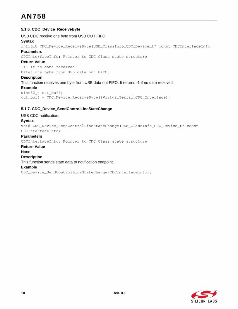
5.1.6. CDC_Device_ReceiveByte
USB CDC receive one byte from USB OUT FIFO.Syntaxint16_t CDC_Device_ReceiveByte(USB_ClassInfo_CDC_Device_t* const CDCInterfaceInfo)ParametersCDCInterfaceInfo: Pointer to CDC Class state structureReturn Value-1: if no data receivedData: one byte from USB data out FIFO.DescriptionThis function receives one byte from USB data out FIFO. It returns -1 if no data received.Exampleuint32_t out_buff;out_buff = CDC_Device_ReceiveByte(&VirtualSerial_CDC_Interface);
5.1.7. CDC_Device_SendControlLineStateChange
USB CDC notification.Syntaxvoid CDC_Device_SendControlLineStateChange(USB_ClassInfo_CDC_Device_t* const CDCInterfaceInfo)ParametersCDCInterfaceInfo: Pointer to CDC Class state structureReturn ValueNoneDescriptionThis function sends state data to notification endpoint.ExampleCDC_Device_SendControlLineStateChange(CDCInterfaceInfo);

AN758
Rev. 0.1 11
5.2. UART FunctionsThis section details the functions found in the gUART0.c file (AN758_USB_CDC\src\generated directory). Thisfile contains the hardware configuration for the SiM3U1xx device.
5.2.1. UART0_enter_default_mode_from_reset
UART0 hardware default configuration.Syntaxvoid UART0_enter_default_mode_from_reset(void)ParametersNoneReturn ValueNoneDescriptionThis function set UART0 TX/RX default configuration as 115200 bps, 8-bit data width, 1 bit stop bit, no-parity ExampleUART0_enter_default_mode_from_reset();
5.2.2. uart_configuration
UART0 configuration setting.Syntaxvoid uart_configuration(uint32_t baud_rate,uint8_t stop_bits,uint8_t parity,uint8_t data_bits)Parametersbaud_rate: baud ratestop_bits: 0 - 1 stop bit; 1 - 1.5 stop bits; 2 - 2 stop bitsparity: 0 - none; 1 - odd; 2 - even; 3 - mark; 4 - spacedata_bits: data bits(5,6,7,8 or 16)Return ValueNoneDescriptionThis function set UART0 TX/RX baud rate, stop bits, parity and data bits.Exampleuart_configuration(115200,0,0,8);
5.2.3. uart_get_data
UART0 get data.Syntaxuint32_t uart_get_data(uint8_t * data)Parametersdata: pointer to receive data bufferReturn ValueThe number of bytes received from UARTDescriptionThis function gets data from UART FIFO to data buffer and return number of bytes received.Exampleuint32_t recv_count;static uint8_t in_buff[64];recv_count = uart_get_data(in_buff);

AN758
12 Rev. 0.1
5.2.4. uart_send_data
UART0 send data.Syntaxvoid uart_send_data(unsigned char *data, unsigned int count)Parametersdata: pointer to send data buffercount: Number of bytes to sendReturn ValueNoneDescriptionThis function send data from data buffer to UART FIFO, transmit data bytes specified in count.Exampleuint32_t send_count = 4;static uint8_t out_buff[64];uart_send_data(out_buff,sendcount);
5.2.5. uart_send_byte
UART0 send one byte.Syntaxvoid uart_send_byte(uint8_t data)Parametersdata: Byte to sendReturn ValueNoneDescriptionThis function sends one byte data to UART FIFOExampleuint8_t out_byte = 0x55;uart_send_byte(out_byte);
5.2.6. uart_get_byte
UART0 get one byte.Syntaxuint8_t uart_get_byte()ParametersNoneReturn ValueByte receivedDescriptionThis function gets one byte data from UART FIFOExampleuint8_t in_byte;In_byte = uart_get_byte();

AN758
Rev. 0.1 13
5.3. Application LayerThe application layer for the USB CDC firmware example can be found in the VirtualSerial.c and Descriptors.cfiles in the AN758_USB_CDC\src\VirtualSerial directory.
5.3.1. vcp_main
Virtual COM port entry function.Syntaxvoid vcp_main(void)ParametersNoneReturn ValueNoneDescriptionThis function initialize USB stack and execute Echo mode or Bridge mode in endless while loop. Exampleenter_default_mode_from_reset();vcp_main();
5.3.2. VCOM_echo
It echo input character to USB virtual COMSyntaxvoid VCOM_echo(void)ParametersNoneReturn ValueNoneDescriptionThis function get byte from USB virtual COM port and send back to virtual COM. User will see echo character in their serial com tool. ExampleVCOM_echo();
5.3.3. VCOM_bridge
It transfer data between USB virtual COM port and UART hardware COM port.Syntaxvoid VCOM_bridge(void)ParametersNoneReturn ValueNoneDescriptionThis function acts as USB to UART bridge function.ExampleVCOM_bridge();

AN758
14 Rev. 0.1
5.3.4. EVENT_USB_Device_ControlRequest
Event handler for control request.Syntaxvoid EVENT_USB_Device_ControlRequest(void)ParametersNoneReturn ValueNoneDescriptionThis function is event handler for the library USB Control Request reception event. It handlers USB CDC special class request from USB host.Exampleif(Endpoint_IsSETUPReceived()){uint8_t* RequestHeader = (uint8_t*)&USB_ControlRequest;
for (uint8_t RequestHeaderByte = 0; RequestHeaderByte < sizeof(USB_Request_Header_t); RequestHeaderByte++) *(RequestHeader++) = Endpoint_Read_8();}EVENT_USB_Device_ControlRequest();
5.3.5. EVENT_CDC_Device_LineEncodingChanged
Event handler for the CDC Class driver Line Encoding Changed event.Syntaxvoid EVENT_CDC_Device_LineEncodingChanged(USB_ClassInfo_CDC_Device_t* const CDCInterfaceInfo)ParametersCDCInterfaceInfo:Pointer to the CDC class interface configuration structureReturn ValueNoneDescriptionThis function change UART configuration according CDC class interface configuration.ExampleCDCInterfaceInfo->State.LineEncoding.BaudRateBPS = Endpoint_Read_32_LE();CDCInterfaceInfo->State.LineEncoding.CharFormat = Endpoint_Read_8();CDCInterfaceInfo->State.LineEncoding.ParityType = Endpoint_Read_8();CDCInterfaceInfo->State.LineEncoding.DataBits = Endpoint_Read_8();
Endpoint_ClearOUT();Endpoint_ClearStatusStage();
EVENT_CDC_Device_LineEncodingChanged(CDCInterfaceInfo);

AN758
Rev. 0.1 15
5.3.6. EVENT_USB_Device_ConfigurationChanged
Event handler for the library USB Configuration changed event.Syntaxvoid EVENT_USB_Device_ConfigurationChanged(void)ParametersNoneReturn ValueNoneDescriptionThis function configures endpoint according USB CDC class interface configuration structure.ExampleEVENT_USB_Device_ConfigurationChanged();
5.3.7. CALLBACK_USB_GetDescriptor
Send back descriptor per Get Descriptor request.Syntaxuint16_t CALLBACK_USB_GetDescriptor(const uint16_t wValue, const uint8_t wIndex, const void** const DescriptorAddress)ParametersNoneReturn ValueDescriptor sizeDescriptionWhen the device receives a Get Descriptor request on the control endpoint, this function is called so that the descriptor details can be passed back and the appropriate descriptor sent back to the USB host.Exampleconst void* DescriptorPointer;uint16_t DescriptorSize;
if ((DescriptorSize = CALLBACK_USB_GetDescriptor(USB_ControlRequest.wValue, USB_ControlRequest.wIndex,&DescriptorPointer )) == NO_DESCRIPTOR){
return;}Endpoint_ClearSETUP();Endpoint_Write_Control_Stream_LE(DescriptorPointer, DescriptorSize);

AN758
16 Rev. 0.1
5.3.8. Macros
#define ENDPOINT_DIR_IN 0x80#define ENDPOINT_DIR_OUT 0x00 /** Endpoint address of the CDC device-to-host notification IN endpoint. */#define CDC_NOTIFICATION_EPADDR (ENDPOINT_DIR_IN | 1)/** Endpoint address of the CDC device-to-host data IN endpoint. */#define CDC_TX_EPADDR (ENDPOINT_DIR_IN | 2)/** Endpoint address of the CDC host-to-device data OUT endpoint. */#define CDC_RX_EPADDR (ENDPOINT_DIR_OUT | 3)/* Size in bytes of the CDC device-to-host notification IN endpoint*/#define CDC_NOTIFICATION_EPSIZE 16/** Size in bytes of the CDC data IN and OUT endpoints. */#define CDC_TXRX_EPSIZE 64
5.3.9. USB CDC Class Interface Structure
USB_ClassInfo_CDC_Device_t VirtualSerial_CDC_Interface ={
.Config ={
.ControlInterfaceNumber = 0,
.DataINEndpoint ={
.Address = CDC_TX_EPADDR,
.Size = CDC_TXRX_EPSIZE,
.Banks = 1,},.DataOUTEndpoint ={
.Address = CDC_RX_EPADDR,
.Size = CDC_TXRX_EPSIZE,
.Banks = 1,},.NotificationEndpoint ={
.Address = CDC_NOTIFICATION_EPADDR,
.Size = CDC_NOTIFICATION_EPSIZE,
.Banks = 1,},
},};
AN758
Rev. 0.1 17
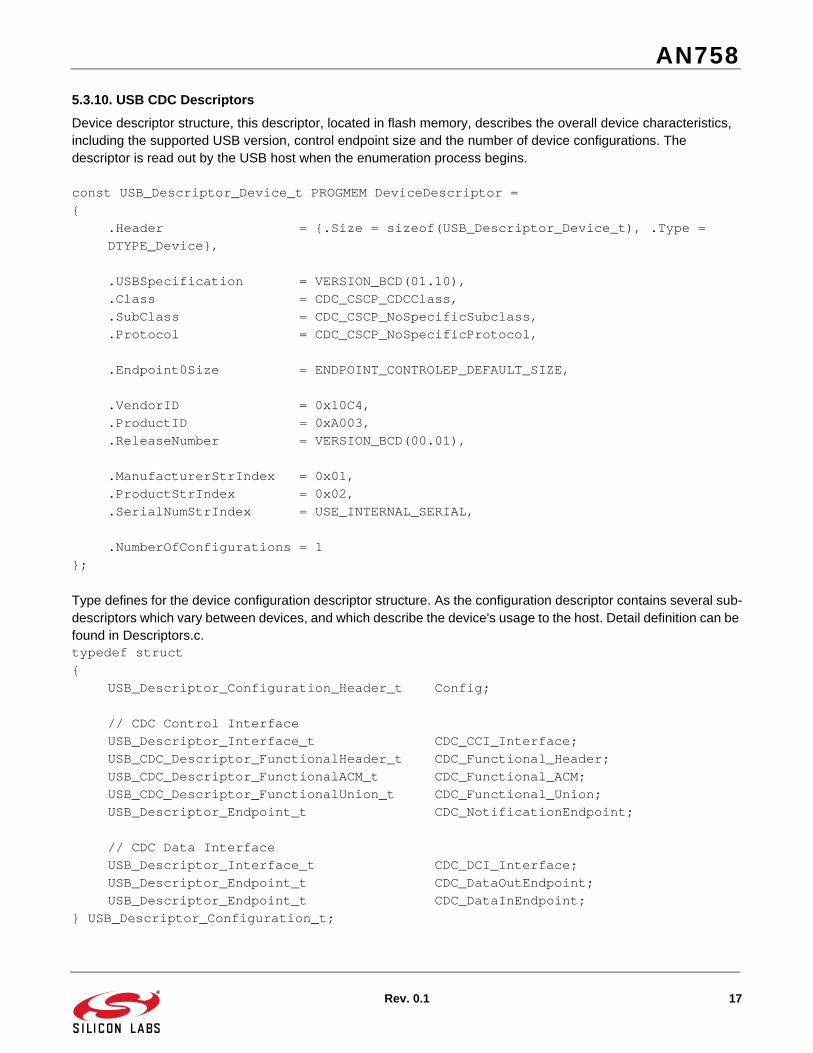
5.3.10. USB CDC Descriptors
Device descriptor structure, this descriptor, located in flash memory, describes the overall device characteristics, including the supported USB version, control endpoint size and the number of device configurations. The descriptor is read out by the USB host when the enumeration process begins.
const USB_Descriptor_Device_t PROGMEM DeviceDescriptor ={
.Header = {.Size = sizeof(USB_Descriptor_Device_t), .Type = DTYPE_Device},
.USBSpecification = VERSION_BCD(01.10),
.Class = CDC_CSCP_CDCClass,
.SubClass = CDC_CSCP_NoSpecificSubclass,
.Protocol = CDC_CSCP_NoSpecificProtocol,
.Endpoint0Size = ENDPOINT_CONTROLEP_DEFAULT_SIZE,
.VendorID = 0x10C4,
.ProductID = 0xA003,
.ReleaseNumber = VERSION_BCD(00.01),
.ManufacturerStrIndex = 0x01,
.ProductStrIndex = 0x02,
.SerialNumStrIndex = USE_INTERNAL_SERIAL,
.NumberOfConfigurations = 1};
Type defines for the device configuration descriptor structure. As the configuration descriptor contains several sub-descriptors which vary between devices, and which describe the device's usage to the host. Detail definition can be found in Descriptors.c. typedef struct{
USB_Descriptor_Configuration_Header_t Config;
// CDC Control InterfaceUSB_Descriptor_Interface_t CDC_CCI_Interface;USB_CDC_Descriptor_FunctionalHeader_t CDC_Functional_Header;USB_CDC_Descriptor_FunctionalACM_t CDC_Functional_ACM;USB_CDC_Descriptor_FunctionalUnion_t CDC_Functional_Union;USB_Descriptor_Endpoint_t CDC_NotificationEndpoint;
// CDC Data InterfaceUSB_Descriptor_Interface_t CDC_DCI_Interface;USB_Descriptor_Endpoint_t CDC_DataOutEndpoint;USB_Descriptor_Endpoint_t CDC_DataInEndpoint;
} USB_Descriptor_Configuration_t;

AN758
18 Rev. 0.1
Example:const USB_Descriptor_Configuration_t ConfigurationDescriptor;String Descriptors#define STR0LEN 4static uint8_t const String0Desc[STR0LEN] ={
STR0LEN, DTYPE_String, 0x09, 0x04}; #define STR1LEN sizeof("SILICON LABORATORIES INC.")*2static uint8_t const String1Desc[STR1LEN] ={...}#define STR2LEN sizeof("SiM3U1xx CDC Class")*2static uint8_t const String2Desc[STR2LEN] ={...}

AN758
Rev. 0.1 19
5.4. USB Low-Level FunctionsThe USB hardware access layer functions are in the AN758_USB_CDC\src\LUFA\Drivers\USB\Core\SIM3Udirectory.
5.4.1. USB_Device_GetFrameNumber
Returns the current USB frame number.Syntaxstatic inline uint16_t USB_Device_GetFrameNumber(void)ParametersNoneReturn ValueCurrent USB frame number from the USB controllerDescriptionThis function returns the current USB frame number, when in device mode. Every millisecond the USB bus is active.Exampleuint16_t PreviousFrameNumber = USB_Device_GetFrameNumber();
5.4.2. USB_Device_SetLowSpeed
Set USB device as low speed.Syntaxstatic inline void USB_Device_SetLowSpeed(void)ParametersNoneReturn ValueNoneDescriptionThis function set USB device as low speed.Exampleif (USB_Options & USB_DEVICE_OPT_LOWSPEED){
USB_Device_SetLowSpeed();}else{
USB_Device_SetFullSpeed();}

AN758
20 Rev. 0.1
5.4.3. USB_Device_SetFullSpeed
Set USB device as full speed.Syntaxstatic inline void USB_Device_SetFullSpeed(void)ParametersNoneReturn ValueNoneDescriptionThis function set USB device as Full speed.Exampleif (USB_Options & USB_DEVICE_OPT_LOWSPEED){
USB_Device_SetLowSpeed();}else{
USB_Device_SetFullSpeed();}
5.4.4. USB_Device_SetDeviceAddress
Set USB device address.Syntaxstatic inline void USB_Device_SetDeviceAddress(const uint8_t Address)ParametersAddress: USB address
Return ValueNoneDescriptionThis function set USB device address assigned from USB host .Exampleuint8_t DeviceAddress = (USB_ControlRequest.wValue & 0x7F);USB_Device_SetDeviceAddress(DeviceAddress);
5.4.5. USB_Device_IsAddressSet
Check USB device address assigned or not.Syntaxstatic inline bool USB_Device_IsAddressSet(void)ParametersNoneReturn ValueUSB device addressDescriptionThis function USB device address assigned or not.ExampleUSB_DeviceState = (USB_Device_IsAddressSet()) ? DEVICE_STATE_Configured : DEVICE_STATE_Powered;

AN758
Rev. 0.1 21
5.4.6. USB_Init
USB hardware initialization.Syntaxvoid USB_Init(const uint8_t Options)ParametersOptions: USB Device Mode OptionReturn ValueNoneDescriptionThis function initializes USB hardware. Set full or low speed. Turn on USB 48 MHz oscillators. Enable USB interrupt. Configure Endpoint to default state. Enable internal pull up resistor to attach USB device.ExampleUSB_Init(USB_DEVICE_OPT_FULLSPEED);
5.4.7. USB0_IRQHandler
USB interrupt handler.Syntaxvoid USB0_IRQHandler(void)ParametersNoneReturn ValueNoneDescriptionThis function handles all enabled USB device interrupt. Clear interrupt flag. Execute handler function.ExampleWhen USB interrupt happened, PC will jump to vector table and then jump into this function.
5.4.8. USB0_ep0_handler
Handle endpoint 0 request.Syntaxvoid USB0_ep0_handler(void)ParametersNone
Return ValueNoneDescriptionThis function handles all endpoint 0 request.Exampleif (usbEpInterruptMask & SI32_USB_A_IOINT_EP0I_MASK){
USB0_ep0_handler();return;
}

AN758
22 Rev. 0.1
5.4.9. USB0_epn_handler
Handle endpoint n request.Syntaxvoid USB0_epn_handler(void)ParametersNoneReturn ValueNoneDescriptionThis function handles all endpoint n request.Exampleif (usbEpInterruptMask & (SI32_USB_A_IOINT_IN1I_MASK | SI32_USB_A_IOINT_OUT1I_MASK)){
Endpoint_SelectEndpoint(1);USB0_epn_handler();
}if (usbEpInterruptMask & (SI32_USB_A_IOINT_IN2I_MASK | SI32_USB_A_IOINT_OUT2I_MASK)){
Endpoint_SelectEndpoint(2);USB0_epn_handler();
}
5.4.10. Endpoint_WaitUntilReady
Wait for endpoint ready.Syntaxuint8_t Endpoint_WaitUntilReady(void)ParametersNoneReturn ValueENDPOINT_READYWAIT_NoError,ENDPOINT_READYWAIT_EndpointStalled,ENDPOINT_READYWAIT_DeviceDisconnected,ENDPOINT_READYWAIT_BusSuspended,ENDPOINT_READYWAIT_TimeoutDescriptionThis function will check endpoint ready status. It set 100ms timeout with counting frame number.Exampleif ((ErrorCode = Endpoint_WaitUntilReady()) != ENDPOINT_READYWAIT_NoError) return ErrorCode;
AN758
Rev. 0.1 23
5.4.11. Endpoint_ConfigureEndpointTable
Configure endpoint.Syntaxbool Endpoint_ConfigureEndpointTable(
const USB_Endpoint_Table_t* const Table, const uint8_t Entries)ParametersTable: pointer to endpoint tableEntries: no use in this softwareReturn ValueTrue: if configure successful.False: if configure failure.DescriptionThis function configures endpoint.Exampleif (!(Endpoint_ConfigureEndpointTable(&CDCInterfaceInfo->Config.DataINEndpoint, 1))) return false;
5.4.12. Endpoint_Write_Control_Stream_LE
Write stream data to control endpointSyntaxuint8_t Endpoint_Write_Control_Stream_LE(const void* const Buffer,
uint16_t Length)ParametersBuffer: pointer to data bufferLength: Transmit lengthReturn ValueENDPOINT_RWCSTREAM_NoErrorDescriptionThis function writes stream data to control endpoint.ExampleEndpoint_Write_Control_Stream_LE(DescriptorPointer, DescriptorSize);

AN758
24 Rev. 0.1
5.4.13. Endpoint_Write_Stream_LE
Write stream data to correspond endpoint.Syntaxuint8_t Endpoint_Write_Stream_LE(const void* const Buffer,
uint16_t Length,uint16_t* const BytesProcessed)
ParametersBuffer: pointer to data bufferLength: Transmit lengthReturn ValueENDPOINT_RWSTREAM_NoError,ENDPOINT_READYWAIT_EndpointStalled,ENDPOINT_READYWAIT_DeviceDisconnected,ENDPOINT_READYWAIT_BusSuspended,ENDPOINT_READYWAIT_TimeoutDescriptionThis function writes stream data to correspond endpoint according usb_ep_selected.ExampleEndpoint_SelectEndpoint(CDCInterfaceInfo->Config.DataINEndpoint.Address);return Endpoint_Write_Stream_LE(Buffer, Length, NULL);
5.4.14. Endpoint_ClearIN
Sends an IN packet to the host on the currently selected endpoint.Syntaxstatic inline void Endpoint_ClearIN(void)ParametersNoneReturn ValueNoneDescriptionThis function Sends an IN packet to the host on the currently selected endpoint. It set IPRDYI = 1 to start USB IN transmits.ExampleCDC_Device_SendData(&VirtualSerial_CDC_Interface, (char *)in_buff, recv_count);Endpoint_ClearIN();

AN758
Rev. 0.1 25
5.4.15. Endpoint_ClearOUT
Acknowledges an OUT packet to the host on the currently selected endpointSyntaxstatic inline void Endpoint_ClearOUT(void)ParametersNoneReturn ValueNoneDescriptionThis function acknowledges an OUT packet to the host on the currently selected endpoint. ExampleCDCInterfaceInfo->State.LineEncoding.BaudRateBPS = Endpoint_Read_32_LE();CDCInterfaceInfo->State.LineEncoding.CharFormat = Endpoint_Read_8();CDCInterfaceInfo->State.LineEncoding.ParityType = Endpoint_Read_8();CDCInterfaceInfo->State.LineEncoding.DataBits = Endpoint_Read_8();
Endpoint_ClearOUT();

AN758
26 Rev. 0.1
6. CDC Driver
The CDC class is implemented in all releases of Windows, and the operating system needs an INF file for the CDCdriver. This INF file contains the Vendor ID and Product ID. If the VID/PID of the USB devices matches the INF file,Windows will load the driver described in the file. The CDC_ACM INF file can be found in theAN758_USB_CDC\src\VirtualSerial directory.
6.1. Installing the DriverTo install the driver on Windows 7:
1. Build the project and download firmware to the SiM3U1xx MCU card.
2. Connect the USB cable between the Device USB connector (J13) and the PC.
3. Open Device Manager. The device will appear under Other devices as the SiM3U1xx CDC Class device.
4. Right-click on the SiM3U1xx CDC Class device and select Update Driver Software.

AN758
Rev. 0.1 27
5. Select Browse my computer for driver software.

AN758
28 Rev. 0.1
6. Enter the directory path of the CDC_ACM.inf file (AN758_USB_CDC\src\VirtualSerial directory). If the Include subfolders option is checked, entering the main sim3u1xx_USB_CDC directory in the workspace is sufficient.
7. Windows will display a warning. Select Install this driver software anyway.
8. When the driver finishes installing, Windows will report the installation results.

AN758
Rev. 0.1 29
9. Open Device Manager and observe the device. It will now appear under Ports (COM & LPT) with an assigned COM port number.

http://www.silabs.com
Silicon Laboratories Inc.400 West Cesar ChavezAustin, TX 78701USA
Simplicity Studio
One-click access to MCU and wireless tools, documentation, software, source code libraries & more. Available for Windows, Mac and Linux!
IoT Portfoliowww.silabs.com/IoT
SW/HWwww.silabs.com/simplicity
Qualitywww.silabs.com/quality
Support and Communitycommunity.silabs.com
DisclaimerSilicon Labs intends to provide customers with the latest, accurate, and in-depth documentation of all peripherals and modules available for system and software implementers using or intending to use the Silicon Labs products. Characterization data, available modules and peripherals, memory sizes and memory addresses refer to each specific device, and "Typical" parameters provided can and do vary in different applications. Application examples described herein are for illustrative purposes only. Silicon Labs reserves the right to make changes without further notice and limitation to product information, specifications, and descriptions herein, and does not give warranties as to the accuracy or completeness of the included information. Silicon Labs shall have no liability for the consequences of use of the information supplied herein. This document does not imply or express copyright licenses granted hereunder to design or fabricate any integrated circuits. The products are not designed or authorized to be used within any Life Support System without the specific written consent of Silicon Labs. A "Life Support System" is any product or system intended to support or sustain life and/or health, which, if it fails, can be reasonably expected to result in significant personal injury or death. Silicon Labs products are not designed or authorized for military applications. Silicon Labs products shall under no circumstances be used in weapons of mass destruction including (but not limited to) nuclear, biological or chemical weapons, or missiles capable of delivering such weapons.
Trademark InformationSilicon Laboratories Inc.® , Silicon Laboratories®, Silicon Labs®, SiLabs® and the Silicon Labs logo®, Bluegiga®, Bluegiga Logo®, Clockbuilder®, CMEMS®, DSPLL®, EFM®, EFM32®, EFR, Ember®, Energy Micro, Energy Micro logo and combinations thereof, "the world’s most energy friendly microcontrollers", Ember®, EZLink®, EZRadio®, EZRadioPRO®, Gecko®, ISOmodem®, Precision32®, ProSLIC®, Simplicity Studio®, SiPHY®, Telegesis, the Telegesis Logo®, USBXpress® and others are trademarks or registered trademarks of Silicon Labs. ARM, CORTEX, Cortex-M3 and THUMB are trademarks or registered trademarks of ARM Holdings. Keil is a registered trademark of ARM Limited. All other products or brand names mentioned herein are trademarks of their respective holders.