Implementing Host Data Loss Prevention Device Control...
28
Implementing McAfee Device Control Security
Transcript of Implementing Host Data Loss Prevention Device Control...

Implementing McAfee Device ControlSecurity

COPYRIGHT
Copyright © 2009 McAfee, Inc. All Rights Reserved.
No part of this publication may be reproduced, transmitted, transcribed, stored in a retrieval system, or translated into any language in any formor by any means without the written permission of McAfee, Inc., or its suppliers or affiliate companies.
TRADEMARK ATTRIBUTIONS
AVERT, EPO, EPOLICY ORCHESTRATOR, FOUNDSTONE, GROUPSHIELD, INTRUSHIELD, LINUXSHIELD, MAX (MCAFEE SECURITYALLIANCEEXCHANGE), MCAFEE, NETSHIELD, PORTALSHIELD, PREVENTSYS, SECURITYALLIANCE, SITEADVISOR, TOTAL PROTECTION, VIRUSSCAN,WEBSHIELD are registered trademarks or trademarks of McAfee, Inc. and/or its affiliates in the US and/or other countries. McAfee Red inconnection with security is distinctive of McAfee brand products. All other registered and unregistered trademarks herein are the sole propertyof their respective owners.
LICENSE INFORMATION
License Agreement
NOTICE TO ALL USERS: CAREFULLY READ THE APPROPRIATE LEGAL AGREEMENT CORRESPONDING TO THE LICENSE YOU PURCHASED,WHICH SETS FORTH THE GENERAL TERMS AND CONDITIONS FOR THE USE OF THE LICENSED SOFTWARE. IF YOU DO NOT KNOW WHICHTYPE OF LICENSE YOU HAVE ACQUIRED, PLEASE CONSULT THE SALES AND OTHER RELATED LICENSE GRANT OR PURCHASE ORDER DOCUMENTSTHAT ACCOMPANY YOUR SOFTWARE PACKAGING OR THAT YOU HAVE RECEIVED SEPARATELY AS PART OF THE PURCHASE (AS A BOOKLET,A FILE ON THE PRODUCT CD, OR A FILE AVAILABLE ON THE WEBSITE FROM WHICH YOU DOWNLOADED THE SOFTWARE PACKAGE). IF YOUDO NOT AGREE TO ALL OF THE TERMS SET FORTH IN THE AGREEMENT, DO NOT INSTALL THE SOFTWARE. IF APPLICABLE, YOU MAY RETURNTHE PRODUCT TO MCAFEE OR THE PLACE OF PURCHASE FOR A FULL REFUND.
License Attributions
Refer to the product Release Notes.
2
ContentsOverview. . . . . . . . . . . . . . . . . . . . . . . . . . . . . . . . . . . . . . . . . . . . . . . . . . . . . . . . . . . . . . . . . . . . . . . . . . . . . . . . . . . .4
Device classes. . . . . . . . . . . . . . . . . . . . . . . . . . . . . . . . . . . . . . . . . . . . . . . . . . . . . . . . . . . . . . . . . . . . . . . . . . . . . 4
How to control hardware devices in McAfee Device Control. . . . . . . . . . . . . . . . . . . . . . . . . . . . . . . . . 4
How device classes are organized. . . . . . . . . . . . . . . . . . . . . . . . . . . . . . . . . . . . . . . . . . . . . . . . . . . . . . 5
Device definitions. . . . . . . . . . . . . . . . . . . . . . . . . . . . . . . . . . . . . . . . . . . . . . . . . . . . . . . . . . . . . . . . . . . . . . . . . . 6
Plug and play device definitions. . . . . . . . . . . . . . . . . . . . . . . . . . . . . . . . . . . . . . . . . . . . . . . . . . . . . . . . 8
Removable storage device definitions. . . . . . . . . . . . . . . . . . . . . . . . . . . . . . . . . . . . . . . . . . . . . . . . . . 15
Device rules. . . . . . . . . . . . . . . . . . . . . . . . . . . . . . . . . . . . . . . . . . . . . . . . . . . . . . . . . . . . . . . . . . . . . . . . . . . . . . 18
Plug and play device rules. . . . . . . . . . . . . . . . . . . . . . . . . . . . . . . . . . . . . . . . . . . . . . . . . . . . . . . . . . . 18
Removable storage device rules. . . . . . . . . . . . . . . . . . . . . . . . . . . . . . . . . . . . . . . . . . . . . . . . . . . . . . . 19
Online and offline modes. . . . . . . . . . . . . . . . . . . . . . . . . . . . . . . . . . . . . . . . . . . . . . . . . . . . . . . . . . . . 19
Examples. . . . . . . . . . . . . . . . . . . . . . . . . . . . . . . . . . . . . . . . . . . . . . . . . . . . . . . . . . . . . . . . . . . . . . . . . . . . . . . . 20
Example 1 - Block the Dell wireless 1490 dual band WLAN mini-card. . . . . . . . . . . . . . . . . . . . . . . . 20
Example 2 - Blocking USB devices. . . . . . . . . . . . . . . . . . . . . . . . . . . . . . . . . . . . . . . . . . . . . . . . . . . . . 23
Example 3 - How to define a new device class. . . . . . . . . . . . . . . . . . . . . . . . . . . . . . . . . . . . . . . . . . . 26
3
OverviewThe following document describes how to implement security for removable devices usingMcAfee Host Data Loss Prevention. The descriptions and examples that follow are taken fromMcAfee Host Data Loss Prevention version 2.2 patch 2, though they are generally applicable inany version.
Because the information that follows applies only to the Device Control component of McAfeeHost Data Loss Prevention, we use the shorthand of referring to the product as McAfee DeviceControl throughout this document. This reduced tool set version is, in fact, the defaultimplementation of McAfee Host Data Loss Prevention when first installed. All of the informationin this document should be understood to apply to full McAfee Host Data Loss Prevention aswell.
Device classes
Device definitions
Device rules
Examples
Device classesA device class is a collection of devices that have similar characteristics and that can be managedin a similar manner. For example, the "Intel® PRO/1000 PL Network Connection" and "Dellwireless 1490 Dual Band WLAN Mini-Card" are two devices that belong to the Network Adapterdevice-class.
McAfee Device Control can control the behavior of device classes and specific devices belongingto a managed device class using device definitions and device rules. The device class definitionsare part of the DLP Policy and is found under the Systems menu in ePolicy Orchestrator 4.0.
How to control hardware devices in McAfee Device Control
How device classes are organized
How to control hardware devices in McAfee Device ControlUse this general procedure to set the behavior of a specific set of hardware devices in McAfeeDevice Control:
Task
1 Verify that the device class to which the hardware devices belong is a Managed DeviceClass.
2 Create a Device Definition that matches the properties of the specific hardware devicesyou want to control.
4

3 Create a Device Rule to set the action to apply to hardware devices matching the devicedefinition in step 2. The action can block the device, monitor it, or set the device toread-only.
Figure 1: The Device Management panel in McAfee Device Control
How device classes are organizedMcAfee Device Control has a built-in list of pre-defined device classes, sorted to three deviceclass categories:
• Managed: device classes whose behavior is controlled by McAfee Device Control. The HostDLP agent installs the DLP device driver on these device classes.
• Unmanageable: device classes that McAfee Device Control does not try to control, forexample battery devices or processors.
• Unmanaged: device classes that are not controlled by the McAfee Device Control defaultconfiguration, but can easily be managed by changing the device class status to Managed(see Figure 2: Changing the decoders device class to Managed.
You can use device definitions and plug and play device rules to control (monitor, block, or setto read-only) hardware devices belonging to a specific device-class only when that device classis set to Managed status.
Removable storage device rules, on the other hand, do not require a Managed device class.The reason is related to the difference in how the two types of device rules utilize device classes:
• Plug and play device rules are triggered when the hardware device is plugged into thecomputer. Since the reaction is to a device driver, the device class must be managed forthe device to be recognized.
• Removable storage device rules are triggered when a new file system is mounted. Whenmount occurs, the DLP agent associates the drive letter with the specific hardware device
OverviewDevice classes
5

and checks the device properties. Since the reaction is to a file system operation (that is,mount of a new file system) the device class does not need to be managed.
NOTE: For instructions on defining a new device class, refer to Example 3 - How to define anew device class at the end of this document.
Figure 2: Changing the decoders device class to Managed
Device definitionsA device definition is a list of device properties such as bus type, device class, vendor ID andproduct ID. The role of device definitions is to identify and group devices according to theircommon device properties.
Some device properties are the same for plug and play device definitions (Figure 3: Plug andplay device definition) and for removable storage device definitions (Figure 4: Removable storagedevice definition), while others are exclusive to the specific device type.
Plug and play device definitions
Removable storage device definitions
OverviewDevice definitions
6

Figure 3: Plug and play device definition
OverviewDevice definitions
7

Figure 4: Removable storage device definition
Plug and play device definitionsThe following sections describe the device definition properties and how to obtain them:
Bus type
A bus is the physical mechanism on which a device is connected to the computer. Commonbuses include USB, PCI, FireWire, and Bluetooth.
When using the bus type definition in a rule, the bus itself is not blocked or monitored. Therule applies only to devices connected on top of that bus. For example, if a rule defines thatthe entire USB bus should be blocked, then any USB device that is connected on top of the USBcontroller (through the USB bus) will be blocked, but the USB controller device will not beblocked since it is connected on top of the PCI bus. In the Figure 5: Devices by connection
OverviewDevice definitions
8
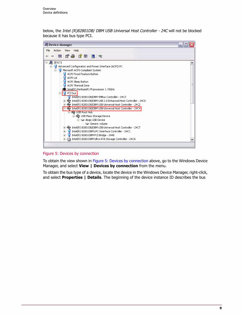
below, the Intel (R)82801DB/ DBM USB Universal Host Controller - 24C will not be blockedbecause it has bus type PCI.
Figure 5: Devices by connection
To obtain the view shown in Figure 5: Devices by connection above, go to the Windows DeviceManager, and select View | Devices by connection from the menu.
To obtain the bus type of a device, locate the device in the Windows Device Manager, right-click,and select Properties | Details. The beginning of the device instance ID describes the bus
OverviewDevice definitions
9

type the device is connected to (see Figure 6: A typical network adapter connected on top ofthe PCI bus).
Figure 6: A typical network adapter connected on top of the PCI bus
NOTE: USB devices require a device called a USB hub to operate. The USB hub device is presentunder all physical USB controllers. Therefore, if a plug and play rule blocks the entire USB busexcept several excluded devices, you must also exclude the USB Hub to allow the operation ofsome USB devices on that computer. (See Example 2 - Blocking USB devices.)
Device class
Microsoft Windows has pre-defined categories for most common devices. However, some devicesinstall their own new device class and don't fall under the pre-existing categories. The deviceclasses available in the device definitions dialog box (see Figure 7: Selecting a device class (thelist contains only the managed device classes)) are taken from the Managed Device Classes
OverviewDevice definitions
10

list in the policy. Devices in the Unmanageable Device Class or in the Unmanaged DeviceClass lists cannot be used in a definition.
Figure 7: Selecting a device class (the list contains only the managed device classes)
OverviewDevice definitions
11

To obtain the device class to which a specific device belongs, look in the Windows DeviceManager (see Figure 8: Device classes as seen in the Windows Device Manager).
Figure 8: Device classes as seen in the Windows Device Manager
Device compatible ID (advanced users only)
The device compatible ID is a string that identifies a device in the computer according to itscharacteristics.
The definition can be obtained in the Windows Device Manager device properties.
OverviewDevice definitions
12
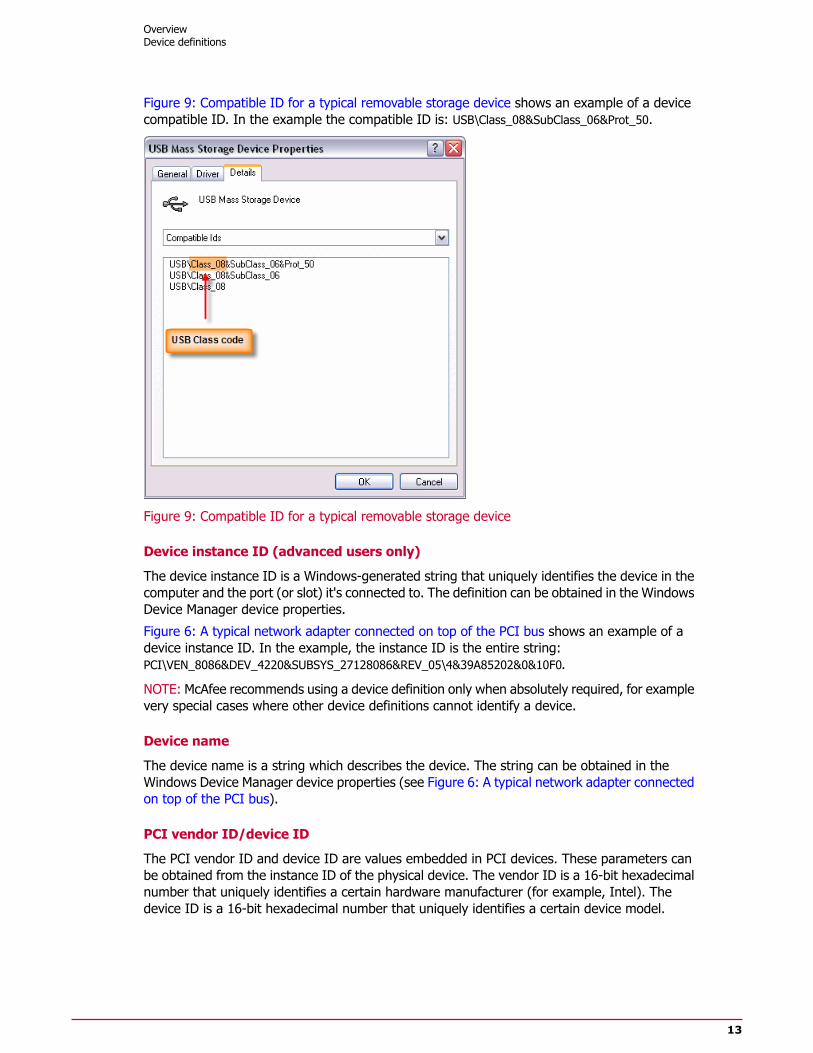
Figure 9: Compatible ID for a typical removable storage device shows an example of a devicecompatible ID. In the example the compatible ID is: USB\Class_08&SubClass_06&Prot_50.
Figure 9: Compatible ID for a typical removable storage device
Device instance ID (advanced users only)
The device instance ID is a Windows-generated string that uniquely identifies the device in thecomputer and the port (or slot) it's connected to. The definition can be obtained in the WindowsDevice Manager device properties.
Figure 6: A typical network adapter connected on top of the PCI bus shows an example of adevice instance ID. In the example, the instance ID is the entire string:PCI\VEN_8086&DEV_4220&SUBSYS_27128086&REV_05\4&39A85202&0&10F0.
NOTE: McAfee recommends using a device definition only when absolutely required, for examplevery special cases where other device definitions cannot identify a device.
Device name
The device name is a string which describes the device. The string can be obtained in theWindows Device Manager device properties (see Figure 6: A typical network adapter connectedon top of the PCI bus).
PCI vendor ID/device ID
The PCI vendor ID and device ID are values embedded in PCI devices. These parameters canbe obtained from the instance ID of the physical device. The vendor ID is a 16-bit hexadecimalnumber that uniquely identifies a certain hardware manufacturer (for example, Intel). Thedevice ID is a 16-bit hexadecimal number that uniquely identifies a certain device model.
OverviewDevice definitions
13
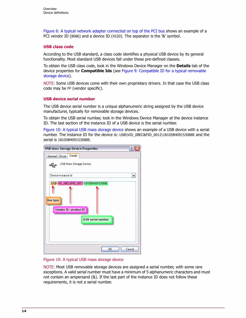
Figure 6: A typical network adapter connected on top of the PCI bus shows an example of aPCI vendor ID (8086) and a device ID (4220). The separator is the '&' symbol.
USB class code
According to the USB standard, a class code identifies a physical USB device by its generalfunctionality. Most standard USB devices fall under these pre-defined classes.
To obtain the USB class code, look in the Windows Device Manager on the Details tab of thedevice properties for Compatible Ids (see Figure 9: Compatible ID for a typical removablestorage device).
NOTE: Some USB devices come with their own proprietary drivers. In that case the USB classcode may be FF (vendor specific).
USB device serial number
The USB device serial number is a unique alphanumeric string assigned by the USB devicemanufacturer, typically for removable storage devices.
To obtain the USB serial number, look in the Windows Device Manager at the device instanceID. The last section of the instance ID of a USB device is the serial number.
Figure 10: A typical USB mass storage device shows an example of a USB device with a serialnumber. The instance ID for the device is: USB\VID_08EC&PID_0012\18105B409153088E and theserial is 18105B409153088E.
Figure 10: A typical USB mass storage device
NOTE: Most USB removable storage devices are assigned a serial number, with some rareexceptions. A valid serial number must have a minimum of 5 alphanumeric characters and mustnot contain an ampersand (&). If the last part of the instance ID does not follow theserequirements, it is not a serial number.
OverviewDevice definitions
14
USB vendor ID/product ID
The USB vendor ID and device ID are embedded in the USB device. The vendor ID uniquelyidentifies the device manufacturer and the device ID identifies a specific device model fromthat manufacturer.
To obtain the vendor ID and product ID look at the device instance ID of the specific device inthe Windows Device Manager. Figure 10: A typical USB mass storage device shows an exampleof a connected USB mass storage device. In the example shown the vendor ID is 08EC and theproduct ID, separated by the '&' character, is 0012.
Removable storage device definitionsRemovable storage device definitions are similar in construct to plug and play device definitions.However, removable storage device definitions add properties that allow maximum flexibilitywhen controlling removable storage devices.
Removable storage devices are physical devices connected to a computer which export one ormore logical disk drive or CD-ROM devices. The logical disk drive or CD-ROM device in turnexports one or more mounts (drive letters). A McAfee Device Control mechanism gathersattributes from the removable storage devices at different layers of the tree when processinga removable storage device rule in order to get as much data as possible about the device touniquely identify it.
Figure 11: A typical removable storage device tree shows an example of a typical removablestorage device tree. It demonstrates at which level an attribute of the device is gathered at.You can see this structure in the device manager when selecting View | Devices byconnection and locating the plugged in removable storage device.
OverviewDevice definitions
15

All removable storage device definitions are defined in the same way as plug and play devicedefinitions. The only difference is where the device attribute is taken from. The following sectiondescribes definition properties that are specific for removable storage devices.
Figure 11: A typical removable storage device tree
CD/DVD drives
CD/DVD drive is a generic device class definition for all CD/DVD devices. This definition istypically used when creating a rule for blocking CD burning.
File system access
The file system access defines whether the file system is writable (a removable storage device)or read-only (for example, compact discs).
OverviewDevice definitions
16

File system type
The file system type can be found by locating the drive letter for the removable storage devicein Windows Explorer and looking at its properties (see Figure 12: Typical storage device inWindows Explorer.)
Figure 12: Typical storage device in Windows Explorer
File system volume label
The file system volume label is a user defined label given to the file system. It can be locatedin Windows Explorer (see Figure 12: Typical storage device in Windows Explorer.)
File system volume serial number
The file system volume serial number is a 32-bit serial number generated automatically whenevera file system is created on the device. To locate the volume serial number, run a command line(Start | Run, then type cmd in the text box) and type dir X: (where x is the drive letter). Atthe top of the results the file system volume serial number can be found. Figure 13: The file
OverviewDevice definitions
17

system volume serial number shows an example of a file system volume serial number (theserial number is 0DD1-0074.)
Figure 13: The file system volume serial number
NOTE: The file system volume serial number changes when reformatting the media. The valuecan be user-modified using a special tool.
Device rulesOnce you have created a device definition to uniquely identify a set of devices, you use devicerules to set the action applied to the hardware devices matching the device definition.
To control devices (monitor, block, set to read-only) that belong to a given device-class, thedevice-class must be configured as a Managed Device Class in the Host DLP managementconsole. (For more information refer to How device classes are organized.)
A device rule can apply the following actions:
• Block — The device is blocked when it is plugged into the computer. Any attempt to usethe device fails.
• Monitor — A DLP event is sent to the ePolicy Orchestrator server to log the activation ofthe device when it is plugged in.
• Notify User — Activates a popup dialog to the user notifying the user of the action thatbeing performed. This action is optional, and is always used with another action (block,monitor).
• Read-only — This action is only available for removable storage devices. The action setsthe device to be read-only, disabling all write operations to the device.
There are two types of device rules, removable storage and plug and play device rules.
Plug and play device rules
Removable storage device rules
Online and offline modes
Plug and play device rulesPlug and play device rules work on the device driver level, and can be used to block and monitordevices. Whenever a new device is plugged into the computer, McAfee Device Control matches
OverviewDevice rules
18

the new device attributes against the device attributes defined in the plug and play device rule.If a match is found, McAfee Device Control performs the action (block/monitor/notify user)defined by the device rule.
Plug and play device rules are used to restrict the use of peripheral devices such as Bluetoothadapters and modems. Although plug and play device rules can also be applied to removablestorage devices, McAfee does not recommend using them for such devices. For controllingremovable storage McAfee recommends using the removable storage device rules
Removable storage device rulesRemovable storage device rules are used for blocking and monitoring removable storage devicessuch as flash drives, MP3 players, and external hard drives. They can block, monitor, or configurethe removable storage to read-only. Whenever a new removable storage device is plugged intothe computer, McAfee Device Control matches the new device properties against the removablestorage device definition used in the removable storage device rule. If a match is found, McAfeeDevice Control performs the action defined by the device rule.
Removable storage device rules work on the file system level, and allow for more flexibility thanplug and play device rules. For example, a removable storage device rule can match a devicebased on its file system type (NTFS, FAT32) or file system volume label. In addition, they providemore accurate device names. A specific example would be an iPod which is recognized by theplug and play mechanism as USB mass storage device. The removable storage rule recognizesit as Apple iPod, which is more meaningful. (This description fits older iPods. The iPod Touchis recognized as a Windows Image Acquisition device.)
McAfee recommends using removable storage device rules, rather than plug and play devicerules, to control all devices that provide removable storage, such as USB mass storage devices,Flash Drives ("Disk on Key"), and CD\DVD.
NOTE: Since plug and play device rules are applied on the device driver level, they are appliedbefore removable storage device rules. The implication is that if a removable storage device isblocked by both types of rule, the removable storage device rule is not applied.
Online and offline modesDevice rules allow assigning an Online/Offline mode to a rule. Online mode means that arule will trigger when the user is connected to the organizational network. McAfee Device Controlassumes users are "online" whenever their computers can connect to the organization's ActiveDirectory (DC) server.
Offline mode means that a rule will trigger even when the user is not connected to theorganization's Active Directory (DC) server. (A user can be connected to the network and stillbe "offline" if there is no connection to the Active Directory server.)
When a Monitor rule triggers offline, the event is stored and sent to the DLP database whenthe computer is reconnected to the server.
Assigning online and offline flags to rules allows for the creation of flexible device rules forsituations when a user is in the organization or outside of it. For example, using these flags itis possible to create a rule that disables wireless adapters while the user is online, but does notblock their use when the user is offline.
OverviewDevice rules
19

ExamplesThe following illustrated examples demonstrate the concepts described above.
Examples
Example 1 - Block the Dell wireless 1490 dual band WLAN mini-card
Example 2 - Blocking USB devices
Example 3 - How to define a new device class
Example 1 - Block the Dell wireless 1490 dual band WLANmini-card
This example demonstrates the three steps required to control the behavior of a hardwaredevice.
Task
1 Verify that the device class to which the hardware devices belong is a Managed DeviceClass.The Dell wireless 1490 Dual Band WLAN Mini-Card is a device of class Network Adapter.Open the Device Classes list and view the Managed device class. If Network Adapterdoes not appear, then locate it right click on it and set it to managed device.
Figure 14: Verifying a managed device class
OverviewExamples
20

2 Create a Device Definition that matches the properties of the specific hardware devicesyou want to control.In our example, we define the Bus Type, Device Class, Device Name and Vender ID/ProductID properties.
Figure 15: Device definition for the Dell wireless mini-card
3 Create a Device Rule to set the action to apply to hardware devices matching the devicedefinition.
OverviewExamples
21

In this example we set the rule to block the device when online, and monitor when bothonline and offline.
Figure 16: Including the definition in the rule
OverviewExamples
22

Figure 17: Adding the blocking action
Example 2 - Blocking USB devicesThis example demonstrates how to create a plug and play device rule to block all USB devicesexcept those on a list of selected devices.
USB devices require a device called a USB Root Hub to operate. A USB Root hub device ispresent under each physical USB controller (that is, connected on top of the USB controller).Multiple USB devices can be connected on top of a USB Root Hub. Therefore if a rule blocksthe entire USB bus except specific excluded devices, the USB Root Hub must also be excludedto allow the operation of excluded USB devices connected on top of it.
OverviewExamples
23

Figure 18: The USB Root Hub as ancestor of any device plugged in to one of it's ports showsthe USB Root Hub and the actual memory stick (disgo USB Device) that is connected on top ofthe hub.
Figure 18: The USB Root Hub as ancestor of any device plugged in to one of it's ports
To block all USB devices except specified devices using a plug and play device rule:
Task
1 Create a new plug and play device definition for the USB Root Hub.
a Under Bus Type select USB.
b Under Device Name click Add New and type USB Root Hub. Select the Allow PartialMatch option and click OK twice.
2 Create a new plug and play device definition to block all USB devices. Under Bus Typeselect USB, then click OK.
3 Create a new plug and play device definition for the allowed devices:
a Under Bus Type select USB.
OverviewExamples
24
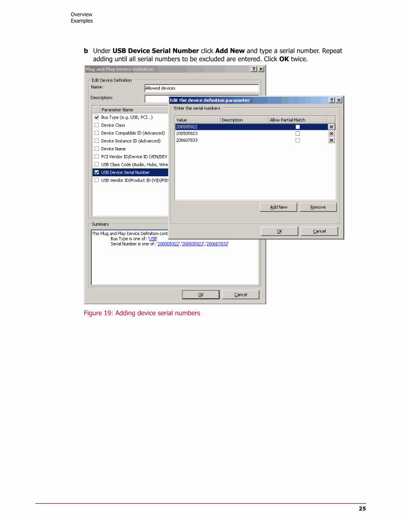
b Under USB Device Serial Number click Add New and type a serial number. Repeatadding until all serial numbers to be excluded are entered. Click OK twice.
Figure 19: Adding device serial numbers
OverviewExamples
25

4 Create a new plug and play device rule. Include All USB devices. Exclude Alloweddevices and USB Root Hub. Click Next and select Block.
Figure 20: Creating a device rule to exclude specified devices
NOTE: This example used a plug and play device rule to demonstrate how devices areconnected on top of each other. The USB Root Hub is connected on top of the USB Controllerand the specific USB devices are connected on top of the USB Root Hub. It also explainsthe need to enable the hub for the excluded USB devices to work. The specific USB devicein the example was a memory stick. Although it is possible to block USB memory devicesin this manner, McAfee recommends using removable storage device rules to block allremovable storage devices.
Example 3 - How to define a new device classMcAfee Device Control has a built-in list of pre-defined device classes. Some hardware devicesinstall their own new device class. To control the behavior of plug and play hardware devicesthat define their own device class you must first add a new device class to the Device Classeslist in the McAfee Device Control policy manager.
A device class is defined by two properties — a name and a GUID (Globally Unique Identifier).The name of a new device is displayed in the device manager, but the GUID is displayed onlyin the Windows Registry and there is no easy way to obtain it. To ease the retrieval of newdevice names and GUIDs, the HDLP agent reports a New Device Class Found event to the HDLPmonitor when a new hardware device class is plugged into the host computer.
To view all new device classes found on all endpoints:
OverviewExamples
26

Task
1 Open the HDLP monitor.
2 Create a filter and select Event Type.
3 Select the devices: new device class found and click OK.
Figure 21: Creating a filter to display new device classes found
4 In the HDLP monitor, select an event from the event list. The Details pane displays theDevice name and Device GUID. Copy these two parameters to Notepad.
Figure 22: Device details in the HDLP monitor
5 Open the HDLP policy manager and navigate to the Device Classes list.
OverviewExamples
27
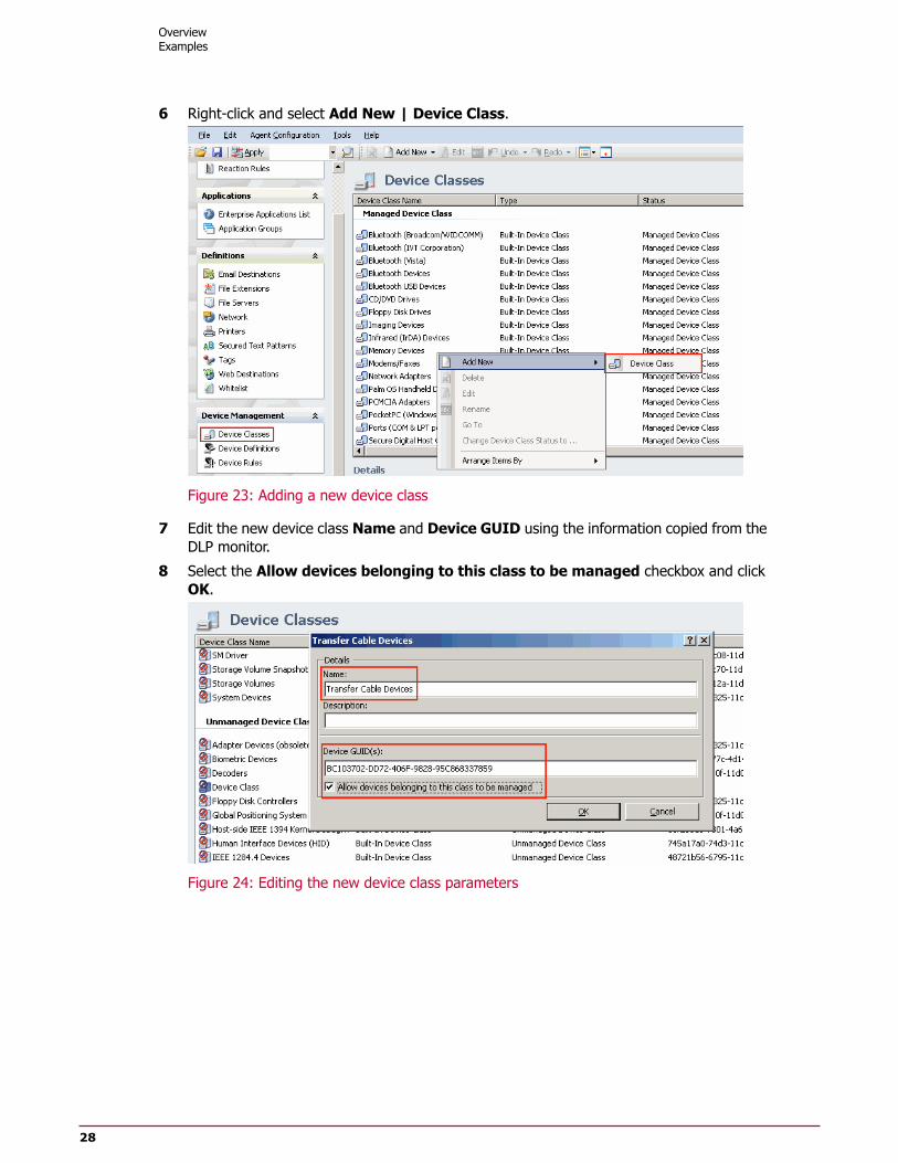
6 Right-click and select Add New | Device Class.
Figure 23: Adding a new device class
7 Edit the new device class Name and Device GUID using the information copied from theDLP monitor.
8 Select the Allow devices belonging to this class to be managed checkbox and clickOK.
Figure 24: Editing the new device class parameters
OverviewExamples
28