
Implementing DDR2 PCB Layout on the TMS320TCI6482 · Preliminary Application Report SPRAAA9C–...
21
Preliminary Application Report SPRAAA9C – June 2006 – Revised May 2010 Implementing DDR2 PCB Layout on theTMS320TCI6482 Michael Shust ........................................................................................ High Speed HW Productization ABSTRACT This application report contains implementation instructions for the DDR2 interface contained on the TCI6482 DSP device. The approach to specifying interface timing for the DDR2 interface is quite different than on previous devices. The previous approach specified device timing in terms of data sheet specifications and simulation models. The customer was required to obtain compatible memory devices, as well as their data sheets and simulation models. The customer would then take this information and design their printed circuit board (PCB) using high speed simulation to close system timing. For the TCI6482 DDR2 interface, the approach is to specify compatible DDR2 devices and provide the PCB routing rule solution directly to the customer. TI has performed the simulation and system design work to ensure DDR2 interface timings are met. The DDR2 system solution is referred to as the TCI6482 DDR2 collateral. This document describes the content of this collateral. The TCI6482 DSK and EVM provide example PCB layouts following these routing rules that pass FCC EMI requirements. The DSK contains a single TCI6482 device and the EVM is a DSK with an attached daughter card containing another TCI6482 device. Both DDR2 layouts on the DSK/EVM meet the routing rules detailed in this document. The customer may copy these DDR2 layouts directly, but the intent is to allow enough flexibility in the routing rules to meet other PCB requirements and allow the customer to derive an optimized layout for their specific application. Contents 1 Prerequisites ................................................................................................................. 2 2 TCI6482 DDR2 Supported Devices ...................................................................................... 2 3 Other Documentation ....................................................................................................... 2 4 Schematics and Electrical Connections .................................................................................. 3 5 Stackup ....................................................................................................................... 5 6 Placement .................................................................................................................... 6 7 Routing ...................................................................................................................... 11 Appendix A Revision History .................................................................................................. 20 List of Figures 1 TCI6482 DDR2 High Level Schematic ................................................................................... 4 2 TCI6482 and DDR2 Device Placement Specification .................................................................. 6 3 Example DDR2 Keep Out Region ........................................................................................ 7 4 PLL and DLL Filters Requirements ....................................................................................... 8 5 Discrete Part Placement .................................................................................................. 10 6 VREF Specification........................................................................................................ 12 7 General Address, Bank Address, Control and Clock Routing ....................................................... 12 8 General Data Byte 0 Routing ............................................................................................ 13 9 General Data Byte 1 Routing ............................................................................................ 13 10 General Data Byte 2 Routing ............................................................................................ 13 11 General Data Byte 3 Routing ............................................................................................ 14 1 SPRAAA9C – June 2006 – Revised May 2010 Implementing DDR2 PCB Layout on the TMS320TCI6482 Copyright © 2006–2010, Texas Instruments Incorporated
Transcript of Implementing DDR2 PCB Layout on the TMS320TCI6482 · Preliminary Application Report SPRAAA9C–...

Preliminary
Application ReportSPRAAA9C–June 2006–Revised May 2010
Implementing DDR2 PCB Layout on theTMS320TCI6482Michael Shust ........................................................................................ High Speed HW Productization
ABSTRACT
This application report contains implementation instructions for the DDR2 interface contained on theTCI6482 DSP device. The approach to specifying interface timing for the DDR2 interface is quite differentthan on previous devices.
The previous approach specified device timing in terms of data sheet specifications and simulationmodels. The customer was required to obtain compatible memory devices, as well as their data sheetsand simulation models. The customer would then take this information and design their printed circuitboard (PCB) using high speed simulation to close system timing.
For the TCI6482 DDR2 interface, the approach is to specify compatible DDR2 devices and provide thePCB routing rule solution directly to the customer. TI has performed the simulation and system designwork to ensure DDR2 interface timings are met. The DDR2 system solution is referred to as the TCI6482DDR2 collateral. This document describes the content of this collateral.
The TCI6482 DSK and EVM provide example PCB layouts following these routing rules that pass FCCEMI requirements. The DSK contains a single TCI6482 device and the EVM is a DSK with an attacheddaughter card containing another TCI6482 device. Both DDR2 layouts on the DSK/EVM meet the routingrules detailed in this document. The customer may copy these DDR2 layouts directly, but the intent is toallow enough flexibility in the routing rules to meet other PCB requirements and allow the customer toderive an optimized layout for their specific application.
Contents1 Prerequisites ................................................................................................................. 22 TCI6482 DDR2 Supported Devices ...................................................................................... 23 Other Documentation ....................................................................................................... 24 Schematics and Electrical Connections .................................................................................. 35 Stackup ....................................................................................................................... 56 Placement .................................................................................................................... 67 Routing ...................................................................................................................... 11Appendix A Revision History .................................................................................................. 20
List of Figures
1 TCI6482 DDR2 High Level Schematic ................................................................................... 4
2 TCI6482 and DDR2 Device Placement Specification .................................................................. 6
3 Example DDR2 Keep Out Region ........................................................................................ 7
4 PLL and DLL Filters Requirements ....................................................................................... 8
5 Discrete Part Placement.................................................................................................. 10
6 VREF Specification........................................................................................................ 12
7 General Address, Bank Address, Control and Clock Routing ....................................................... 12
8 General Data Byte 0 Routing ............................................................................................ 13
9 General Data Byte 1 Routing ............................................................................................ 13
10 General Data Byte 2 Routing ............................................................................................ 13
11 General Data Byte 3 Routing ............................................................................................ 14
1SPRAAA9C–June 2006–Revised May 2010 Implementing DDR2 PCB Layout on the TMS320TCI6482
Copyright © 2006–2010, Texas Instruments Incorporated
Preliminary
Prerequisites www.ti.com
12 Routing Spacing, Matching, and Topology Requirements for ADDRL_CTRL and CK Net Classes ........... 17
13 Route Spacing, Matching, and Topology Requirements for the DQBn and DQBSn Net Classes.............. 18
14 Route Spacing, Matching, and Topology Requirements for the DQGATEL and DQGATEH Net Classes .... 19
List of Tables
1 Compatible JEDEC DDR2 Devices....................................................................................... 2
2 Minimum PCB Stackup..................................................................................................... 5
3 DDR2 Signal Terminations ............................................................................................... 11
4 Clock Net Classes......................................................................................................... 14
5 Signal Net Classes ........................................................................................................ 15
6 Revisions ................................................................................................................... 20
1 Prerequisites
1.1 High Speed Design
While the goal of the TCI6482/Device_Name2_Short collateral is to make system implementation easierfor the customer by providing the system solution, it is still expected that the PCB design work besupervised by a knowledgeable high speed PCB designer as an assumption is made that the PCBdesigner is using established high speed design rules. Ground plane cuts should be avoided if at allpossible as they are tricky to do correctly. Crosstalk and EMI impacts due to PCB design should beevaluated as the PCB design progresses as it can be difficult to go back and fix issues later. Thoroughplanning will aid in the design cycle.
1.2 Familiarity with the JEDEC DDR2 Specification
The DDR2 interface on the TCI6482/Device_Name2_Short device is designed to be compatible with theJEDEC JESD-79A DDR2 specification. It is assumed that the reader is familiar with this specification andthe basic electrical operation of the interface. In addition, several memory manufacturers provide detailedapplication notes on DDR2 operation.
2 TCI6482 DDR2 Supported Devices
Table 1 shows the parameters of the JEDEC DDR2 devices that are compatible with this interface.Generally, the DDR2 interface is compatible with x16 DDR2-533 speed grade DDR2 devices.
Table 1. Compatible JEDEC DDR2 Devices
No. Parameter Min Max Unit Notes
1 JEDEC DDR2 Device Speed Grade DDR2-533 See (1)
2 JEDEC DDR2 Device Bit Width x16 x16 Bits
3 JEDEC DDR2 Device Count 1 2 Devices See (2)
4 JEDEC DDR2 Device Ball Count 84 92 Balls See (3)
(1) Higher DDR2 speed grades are supported due to inherent JEDEC DDR2 backwards compatibility.(2) 1 DDR2 device is used for 16 bit DDR2 memory system. 2 DDR2 devices are used for 32 bit DDR2 memory system.(3) 92 ball devices retained for legacy support. New designs will migrate to 84 ball DDR2 devices. Electrically, the 92 and 84 ball
DDR2 devices are the same.
3 Other Documentation
Specific examples of the implementation of this specification including schematics and a PCB layout canbe obtained from the TCI6482 DSK documentation. In addition, the interested reader is referred to theHigh Speed DSP Systems Design Guide (SPRU889).
For configuration of the DDR interface, refer to the TMS320TCI648x DSP DDR2 Memory Controller User'sGuide (SPRU894).
2 Implementing DDR2 PCB Layout on the TMS320TCI6482 SPRAAA9C–June 2006–Revised May 2010
Copyright © 2006–2010, Texas Instruments Incorporated

Preliminary
www.ti.com Schematics and Electrical Connections
4 Schematics and Electrical Connections
Figure 1 shows a high level schematic of the DDR2 interface. Specific pin numbers can be obtained fromthe TCI6482 and JEDEC DDR2 data sheets. The 32 bit DDR2 interface of TCI6482 is connected to two16 bit DDR2 devices, thus the clock, address, and control connections are three point nets and the datalines are point to point nets.
3SPRAAA9C–June 2006–Revised May 2010 Implementing DDR2 PCB Layout on the TMS320TCI6482
Copyright © 2006–2010, Texas Instruments Incorporated

DED0
DED7DSDDQM0DSDDQS0DSDDQS0
DED8
DED15DSDDQM1
DSDDQSDSDDQS
DQ0
DQ7LDMLDQSLDQS#
DQ8
DQ15UDMUDQSUDQS#
BA0
BA2A0
A13CS#CAS#RAS#WE#CKECKCK#
VREF
DQ0
DQ7LDMLDQSLDQS#
DQ8
DQ15UDMUDQSUDQS#
BA0
BA2A0
A13CS#CAS#RAS#WE#CKECKCK#
VREF
DED16
DED23DSDDQM2DSDDQS2DSDDQS2
DED24
DED31DSDDQM3BSDDQS3BSDDQS3
DBA0
DBA2DEA0
DEA13DCE
DSDCASDSDRASDSDWE
DSDCKEDDR2CLKOUTDDR2CLKOUT
DEODT1ODT
ODTDEODT0
VREF
1 K Ω 1%
Vio 1.8*
0.1µF**0.1µF**0.1µF**
TCI6482 DDR2
DDR2
NC
NC
DSDDQGATE0DSDDQGATE1DSDDQGATE2DSDDQGATE3
1 K Ω 1%
Terminator, if desired. See terminator comments.* Vio1.8 is the power supply for the DDR2 memories and TCI6482 DDR2 interface.** One of these capacitors can be eliminated if the divider and its capacitors are placed near a device VREF pin.
T
0.1µF**
0.1µF**
T
T
TT
T
T
T
TTT
T
T
T
T
TT
T
TTTT
T
T
T
T
T
T
T
T
T
T
T
T
Preliminary
Schematics and Electrical Connections www.ti.com
Figure 1. TCI6482 DDR2 High Level Schematic
4 Implementing DDR2 PCB Layout on the TMS320TCI6482 SPRAAA9C–June 2006–Revised May 2010
Copyright © 2006–2010, Texas Instruments Incorporated

Preliminary
www.ti.com Stackup
4.1 Differences Between the TCI6482 DDR2 Interface and the Typical PC Application
There are some subtle differences between the embedded DDR2 application used on TCI6482 and thetypical PC motherboard/DDR2 DIMM application. The TCI6482 DDR2 interface does not use stub seriestermination (the SST in SSTL). Stub series terminators are parallel terminators and they are not used inthis case due to their high power consumption. Consequently, the termination voltage, Vtt, is also not usednor is it required for the TCI6482 DDR2 interface. The terminators shown in Figure 1 are series resistorterminators.
4.2 DDR2 Power Supplies
The power supply for the DDR2 interface is 1.8 V ± 0.1 V. This power supply is used for theTCI6482/Device_Name2_Short DDR2 power pins (DVDD18) as well as the JEDEC DDR2 devices. VREF isderived from the DDR2 power supply via a resistive divider. Bypassing for the 1.8 V and VREF suppliesare covered in this document.
4.3 Signal Terminations
In order to meet the maximum interface speed (267MHz/533Mbps) memory device drive strength,configurable by bit A1 in the memory device EMRS1 register, should be set to 100% strength. Thisrequires the series terminations which are specified in Section 6.3.4 to avoid excessiveunder-shoot/over-shoot. If 60% drive strength mode is used, series terminations can be eliminated but themaximum operating frequency is reduced to 200MHz/400Mbps. The no termination approach for newdesigns is not without risk, however.
Terminations on the PCB will allow the DDR2 signals to be tuned to meet EMI certification requirements.A PCB which fails EMI certification without terminations will likely have to be re-spun in order to addressthe EMI shortcomings. It can take multiple PCB spins to correct EMI issues. Note that re-spinning a densenon-terminated PCB layout to include terminators can be a very difficult effort because physical room mustbe made for the terminations. This means an entire PCB design may have to be redone. It is much easierto remove terminations rather than adding them after the PCB has been found to fail EMI.
Customers who are sensitive to the cost/schedule issues with respect to EMI may wish to includeterminations on their boards even though they plan not to have terminations on the final product. This way,the terminations can easily be replaced with zero ohm resistors and checked for EMI compliance. If thePCB fails EMI, it is then straightforward to install the necessary terminations without re-spinning the PCB.Once the termination scheme has been verified to pass EMI, the remaining zero ohm terminations can becarefully removed from the PCB layout in a single PCB design spin.
5 Stackup
The minimum stackup required for routing TCI6482 is a 6 layer stack as shown in Table 2. Additionallayers may be added to the PCB stack up to accommodate other circuitry or to reduce the size of theTCI6482/DDR2 PCB footprint.
Table 2. Minimum PCB Stackup
Layer Type Description
1 Signal Top Routing Mostly Horizontal
2 Plane Ground
3 Plane Power
4 Signal Internal Routing
5 Plane Ground
6 Signal Bottom Routing Mostly Vertical
5SPRAAA9C–June 2006–Revised May 2010 Implementing DDR2 PCB Layout on the TMS320TCI6482
Copyright © 2006–2010, Texas Instruments Incorporated

Center ofTCI6482 device
A
A
DDR2devices1280
1660
650
A
650
Furthest DDR2signal ball
Maximum placement distances from center of TCI6482
package to furthest DDR2 signal ball. Does not include
distances to possible DDR2 NC outrigger balls. All
dimesions in mils.
Preliminary
Placement www.ti.com
Systems utilizing the RIO interface should have the target PCB impedance optimized for the differentialimpedance required by that interface. Single ended controlled impedance with a nominal value between50 and 60 ohms is acceptable for the DDR2 interface. DDR2 impedance should be controlled to within+/-15% of its nominal impedance.
5.1 Ground Reference Planes
It is critical that all signal routing layers have a ground reference plane, meaning that there is a full,contiguous ground plane next to every DDR2 routing layer. Two routing layers can share a ground plane(one signal layer above, and one signal layer below the ground plane). Ground plane cuts are not allowedin the DDR2 region (Ground plane cuts are generally a bad idea, and should only be done very carefully,only if absolutely necessary on other areas of the PCB). The purpose of the ground plane is to provide apath for return currents to minimize crosstalk and EMI. Power planes cannot be used as signal returns forthe DDR2 interface. Improper ground plane stackup will likely cause the DDR2 interface to fail or operateunreliably.
5.2 Stackup Routing Impacts
The internal routing planes (stripline) have different flight times than top/bottom (microstrip) routing planes.Ideally the trace routes within the same net class (covered in detail in Section 7.4) should either all bemicrostrip or stripline so that trace length matching can be done. If a combination of microstrip andstripline is used within a net class the trace length should be adjusted to offset the delay difference. Thetrace flight times for microstrip and stripline should be determined for the specific board stackup beingused.
6 Placement
Figure 2 shows the required placement of the TCI6482 device as well as the DDR2 devices. Thedistances shown are maximums and there are no restrictions on how close the devices can be to eachother. Generally, closer is better both from a cost and signal integrity point of view, but the tightness of thelayout will be limited by the room required by the signal traces. Note that minimum placement is usuallylimited by the number of vias required to route the design, not the traces themselves. The PCB designerneeds to take the routing requirements into consideration while determining placement.
Figure 2. TCI6482 and DDR2 Device Placement Specification
6.1 Minimizing PCB Area
The maximum placement and minimum PCB stackup uses the lowest cost PCB technology and generallyresults in the lowest unit cost PCB at the penalty of the largest footprint for the DDR2 interface. Customersneed to evaluate the cost/benefit tradeoffs of smaller feature sizes and additional signal layers for theirsystems. Note that the minimum feature size and stackup may be limited by other circuitry on the PCB.
6 Implementing DDR2 PCB Layout on the TMS320TCI6482 SPRAAA9C–June 2006–Revised May 2010
Copyright © 2006–2010, Texas Instruments Incorporated

A
A
DDR2devices
TCI6482device
A
Example DDR2 keepout region. Region should
encompass all DDR2 circuitry and will vary depending on
placement. Non−DDR2 signals shall not be routed on the
DDR2 signal layers. Non−DDR2 signals may be routed in
this region provided they are routed on layers
separated from DDR2 signal layers by a ground layer. No
breaks shall be allowed in the reference ground layers in
this region. In addition, 1.8V power plane should cover the
entire keep out region.
Preliminary
www.ti.com Placement
6.2 DDR2 Keep Out Region
Figure 3 shows an example DDR2 keep out region. This keep out region will vary with the individualdesign. Its purpose is to ensure other signals do not interfere with the DDR2 interface. The only signalsallowed on the DDR2 signal layers are those for this interface. The 1.8V power partial plane shouldencompass at least the entire DDR2 keep out region.
Figure 3. Example DDR2 Keep Out Region
6.3 Discrete Device Placement
The TCI6482 DDR2 interface uses a number of discrete devices consisting of resistors, resistor packs,capacitors, and EMI filters. Figure 5 shows an example placement of discrete devices around TCI6482and the DDR2 devices. It is useful to refer to it while reading the next sections.
6.3.1 PLL and DLL Filters
The PLL and DLL power supply pins on the TCI6482 device draw small currents, but they are noisesensitive. All the PLL and DLL power supplies are derived from the Vio1.8 supply. Each supply filters theVio1.8 using a filter circuit and two capacitors. Figure 4 shows the placement and routing rules for the PLLand DLL power supplies. The filter capacitors are 0402 in physical size. Note that the PLLV1 is the PLL forthe CPU core clock but is covered in this solution since it impacts the placement and layout of the DDRinterface.
7SPRAAA9C–June 2006–Revised May 2010 Implementing DDR2 PCB Layout on the TMS320TCI6482
Copyright © 2006–2010, Texas Instruments Incorporated

In
GND
Out
0.1µF pF
560
PLLV1
EMI filter TCI6482 pin
GND
In Out
µF0.1
PLLV2
GND
In Out
µF0.1
VDDDLL1
GND
In Out
µF0.1
VDDDLL0
Vio1.8
560pF
560pF
560pF
Center of EMI Filter component should be placed no
longer than 350 mils from associated TCI6482 ball.
Capacitors shown in this figure should be placed in
between EMI filter and the TCI6482 ball.
Traces for the nets in this figure should be 15 mils wide
minimum. Necking down for BGA fanout is acceptable.
Preliminary
Placement www.ti.com
Figure 4. PLL and DLL Filters Requirements
6.3.2 Resistors and Resistor Packs
The TCI6482 DDR2 interface uses resistors for VREF generation and may use resistors or resistor packsfor signal terminations. Specific placement requirements for these components are specified by the routingrules for VREF and the other net classes of the interface. These routing rules are presented later in thisdocument.
Generally speaking, termination resistors can be either discrete resistors or resistor packs and they areplaced in between the DDR2 memories and the TCI6482. The VREF divider resistors will be placedsomewhere in between the DDR2 devices and the TCI6482.
6.3.3 Decoupling Capacitors
Decoupling capacitors are critical to the reliable operation of a high speed PCB. Great care should betaken to ensure the following guidelines are followed. Failure to follow these guidelines will likely result inan unstable system.
For details on the overall quantity and type of decoupling and bulk capacitors refer to the TMS320TCI6482Design Guide and Comparisons to TMS320TCI100 (SPRAAC7). The small decoupling capacitors shouldbe 0402 size or smaller.
8 Implementing DDR2 PCB Layout on the TMS320TCI6482 SPRAAA9C–June 2006–Revised May 2010
Copyright © 2006–2010, Texas Instruments Incorporated

Preliminary
www.ti.com Placement
Exact placement of capacitors is not critical. Figure 5 is an example placement. Decoupling capacitorsshould be placed near the device being decoupled. Distance from the capacitor to the power pins beingdecoupled should not exceed 125 mils.
6.3.3.1 Decoupling Capacitor Vias, Connections to Power Planes, and Placement
Each decoupling capacitor requires two vias, one for each pin. Via sharing for decoupling capacitors is notpermitted. This is due to the inductance of the vias. Via sharing seriously compromises the performance ofthe decoupling capacitor due to this inductance. For the same reason, sharing of vias by power andground pins of the TCI6482 or DDR2 devices is also not permitted. Vias used for decoupling capacitor anddevice power connections are referred to as power vias.
To minimize inductance, power vias should be as large as possible. Use care to ensure power vias arenot so large as to inadvertently cut planes. Power vias should be connected to the device pads with theshortest possible traces that are as wide as possible. Ideally, the trace length from the power via to thedevice pad should not exceed 30 mils. Maximum trace length from power via to decoupling capacitor is 60mils. Maximum trace length from power via to power ball pad is 35 mils.
Figure 5 shows an example placement for the decoupling capacitors. Placement of the bulk capacitors isnot that critical and they can be placed to accommodate other circuitry with more constrained placementand routing requirements. The PCB designer should keep the trace length specifications in this section inmind when placing the capacitors.
9SPRAAA9C–June 2006–Revised May 2010 Implementing DDR2 PCB Layout on the TMS320TCI6482
Copyright © 2006–2010, Texas Instruments Incorporated

ÈÈÈÈÎÎÎÈÈÈÈÎÎÎÎÎÎÏÏÏÏÏÏÏÏÎÎÎÎÎÎÎÎÎÎÎÎDDR2 devices
Top
TCI6482 device
A1
A1
A1
A1
A1A1
ÎÎÎÎÎÎÎÎÎÎÎÎÏÏÏÏÏÏBottom
(looking through
PCB)ÏÏÏÏÏÏ
VREF resistor
VREF cap
VRIO cap
1.5V cap
3.3V cap
PLL cap
Vcore cap
1.8V cap
EMI filter
DLL cap
KeyÏÏÏÏÏÏÏÏÎÎÎÎÎÎ
Preliminary
Placement www.ti.com
Figure 5. Discrete Part Placement
6.3.4 DDR2 Signal Terminations
Series terminations are required if the DDR device is operated at 100% strength. The combination ofseries terminations and 100% drive strength can provide operation up to 267MHz. Termination is notrequired to meet reflection and overshoot specifications provided the DDR2 device is operated at 60%strength, but no termination and 60% strength limits the operating frequency to 200MHz.
10 Implementing DDR2 PCB Layout on the TMS320TCI6482 SPRAAA9C–June 2006–Revised May 2010
Copyright © 2006–2010, Texas Instruments Incorporated

Preliminary
www.ti.com Routing
Recommended terminations are shown in Table 3 . There is room in the placement shown in Figure 2 forthe terminations in Table 3. Termination values may have to be adjusted once hardware is available topass EMI regulations.
Table 3. DDR2 Signal Terminations
Net Class Termination
CK 10 ohm series resistor/resistor packs located near DSP
ADDR_CTRL 22 ohm series resistor/resistor packs located near DSP
DQB0 (DED0-DED7) 22 ohm series resistor/resistor packs located near DDR2
DQB0 (DSDDQM0) 22 ohm series resistor/resistor packs located near C6482
DQB1 (DSDDQM1) 22 ohm series resistor/resistor packs located near C6482
DQSB0 22 ohm series resistor/resistor packs located near DDR2
DQB1 (DED8-DED15) 22 ohm series resistor/resistor packs located near DDR2
DQSB1 22 ohm series resistor/resistor packs located near DDR2
DQB2 (DED16-DED23) 22 ohm series resistor/resistor packs located near DDR2
DQB2 (DSDDQM2) 22 ohm series resistor/resistor packs located near C6482
DQSB2 22 ohm series resistor/resistor packs located near DDR2
DQB3 (DED24-DED31) 22 ohm series resistor/resistor packs located near DDR2
DQB3 (DSDDQM3) 22 ohm series resistor/resistor packs located near C6482
DQSB3 22 ohm series resistor/resistor packs located near DDR2
DQGATEL 10 ohm series resistor/resistor packs located near DQGATE0
DQGATEH 10 ohm series resistor/resistor packs located near DQGATE2
7 Routing
7.1 Required PCB Feature Sizes
The minimum PCB feature sizes referenced in this document are the largest that can be accommodated inorder to physically route the PCB due to the size of the BGA packages. Smaller feature sizes can also beused as well to improve PCB density as long as the routing rules are followed.
The PCB routing rules in this document assume a minimum PCB route width and spacing of 4 mils. ThePCB route trace width is defined as w for the purposes of defining minimum trace separation for thevarious net classes discussed later in the routing rules. Thus, if the PCB is designed with the widestpossible traces, then the trace width is w = 4 mils.
Pad stacks for the DDR2 and TCI6482 BGA pads should be 14 mil diameter copper with 20 mil diametersolder masks (non-solder mask defined pads). Escape and general DDR2 routing vias should have 8 milholes with 18 mil pads. BGA escape is accomplished by the typical dog bone method.
It is also a good idea to maximize the size of the vias used for decoupling capacitors and power pins. Thisis done to minimize via inductance. It is the via and decoupling capacitor stray inductance that limits theperformance of the decoupling capacitors. Use care to ensure that vias are not sized so large as to cut offa portion of a plane.
7.2 VREF
VREF is used by the input buffers of the DDR2 memories as well as TCI6482’s DDR2 interface todetermine logic levels. VREF is specified to be ½ the power supply voltage and is created using a voltagedivider constructed from two 1K ohm, 1% tolerance resistors, see Figure 1. VREF is not a high currentsupply, but it is important to keep it as quiet as possible with minimal inductance. The minimum nominaltrace width for VREF is 20 mils. Necking down VREF to accommodate BGA escape and localized viacongestion is acceptable, but care should be taken to keep VREF 20 mils wide as much as possible.VREF is a DC net and as such, trace delay is not critical, however, overall trace length should be kept to aminimum. The four or five decoupling capacitors on the VREF net are intended to reduce AC noise. Twoare used at the divider, and one each is used near the VREF input of the three loads (2 DDR2’s andTCI6482). See Figure 6.
11SPRAAA9C–June 2006–Revised May 2010 Implementing DDR2 PCB Layout on the TMS320TCI6482
Copyright © 2006–2010, Texas Instruments Incorporated

TCI6482device
A1
A1
A1
DDR2 device
VREF nominal minimumtrace width is 20 mils
VREF DecouplingCapacitor
Neck down to minimum in BGA escaperegions is acceptable. Narrowing toaccomodate via congestion for shortdistances is also acceptable. Bestperformance is obtained if the widthof VREF is maximized.
A1
A1
A1
Center ofTCI6482 device
CLKN/PADDR/BA/CTRL
Address/BA/Control Routing
Preliminary
Routing www.ti.com
Figure 6. VREF Specification
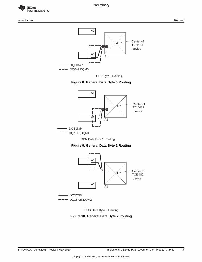
7.3 General DDR2 Routing
Figure 7 through Figure 11illustrate the general routing of the DDR2 interface. The address, bank address,control signals, as well as the DDR2 clock route from the center of the TCI6482 device to the DDR2devices in a “balanced T” route. Each data byte is routed point to point, with the lower two bytes routing tothe lower DDR2 memory and the upper two bytes routing to the upper DDR2 memory. The figures showthe maximum PCB area placement. Tighter placements are achieved by reducing feature size and/oradding PCB layers and pulling the DDR2 memories toward each other and/or closer to the TCI6482device. The routing of the DDR2 interface should look similar to these figures when a proper placement isused. Note that the most extreme minimum placement of DDR2 devices, overlapping each other with oneon the top and the other on the bottom of the PCB should work; however, all routing rules must still befollowed. This type of placement will require advanced PCB technology.
Figure 7. General Address, Bank Address, Control and Clock Routing
12 Implementing DDR2 PCB Layout on the TMS320TCI6482 SPRAAA9C–June 2006–Revised May 2010
Copyright © 2006–2010, Texas Instruments Incorporated
A1
A1
A1
Center ofTCI6482 device
DQS0N/PDQ0−7,DQM0
DDR Byte 0 Routing
A1
A1
A1
Center ofTCI6482 device
DQS1N/P
DQ7−15,DQM1
DDR Data Byte 1 Routing
A1
A1
A1
Center ofTCI6482 device
DQS2N/P
DQ16−23,DQM2
DDR Data Byte 2 Routing
Preliminary
www.ti.com Routing
Figure 8. General Data Byte 0 Routing
Figure 9. General Data Byte 1 Routing
Figure 10. General Data Byte 2 Routing
13SPRAAA9C–June 2006–Revised May 2010 Implementing DDR2 PCB Layout on the TMS320TCI6482
Copyright © 2006–2010, Texas Instruments Incorporated

A1
A1
A1
Center ofTCI6482 device
DQS3N/P
DQ23−31,DQM3
DDR Data Byte 3 Routing
Preliminary
Routing www.ti.com
Figure 11. General Data Byte 3 Routing
7.4 Signal Routing Rules
The routing rules for the TCI6482 DDR2 system design are divided among net classes. Each net classcontains all the signals within a clock domain. There are five clock domains: CK, DQS0, DQS1, DQS2,and DQS3. The general requirement is to skew match within a domain and to minimize crosstalk.Crosstalk across domains is especially troublesome and steps should be taken to minimize couplingbetween signals in different domains.
7.4.1 Net Classes
7.4.1.1 Clock Net Classes
Net classes are used to associate the assorted groups of nets in the DDR2 interface to each other andtheir clock domain. These net classes are used in the DDR2 routing rules. The DDR2 interface has fiveclock net classes, four of which are bi-directional. The clock net classes are shown in Table 4.
All of the clock signals in the TCI6482 DDR2 interface are differential signals. As such, each clock domainnet class needs to be routed as a differential signal with matched lengths for the non-inverting andinverting signals. Differential impedance should also be controlled.
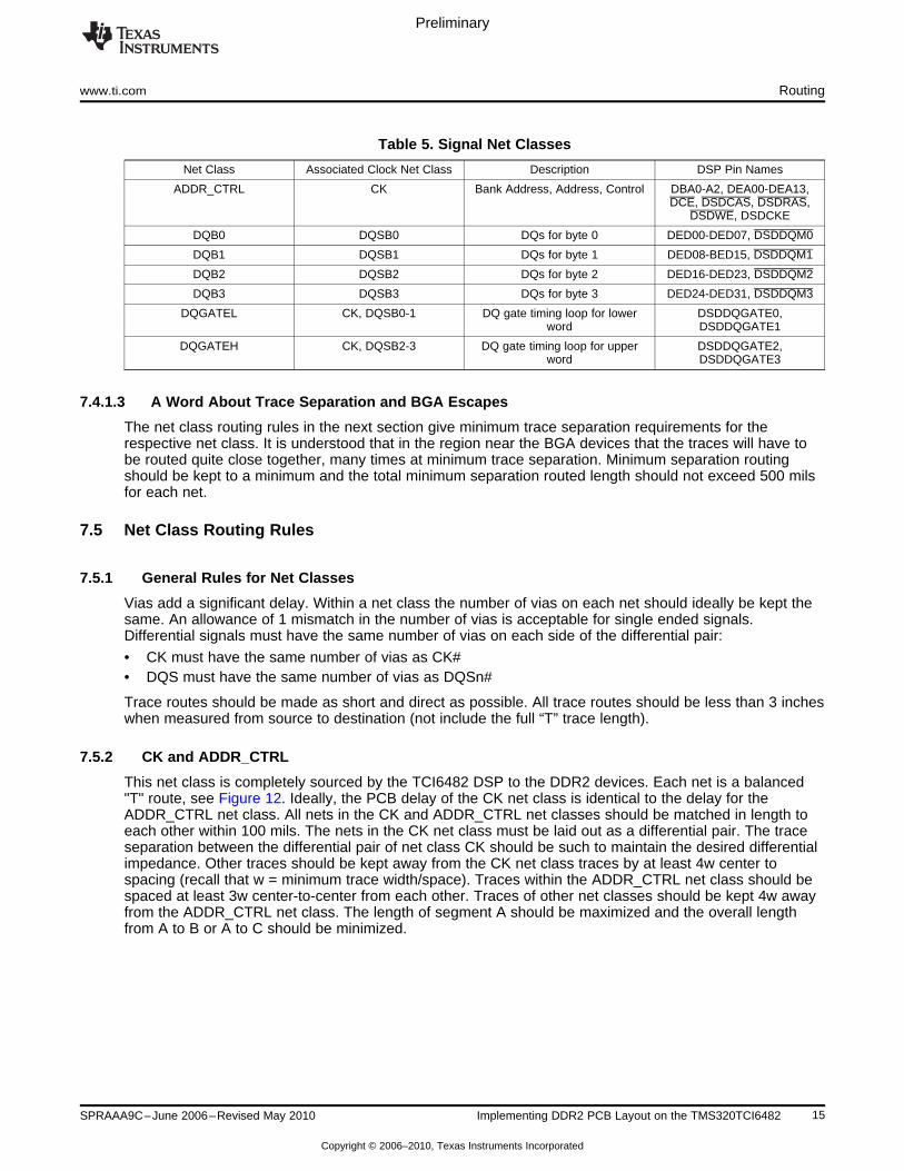
7.4.1.2 Signal Net Classes
Table 5 shows the seven additional net classes that use the clock net classes as their reference.Generally speaking, the nets within a net class and their associated clock net class should be skewmatched to each other. The goal is to minimize the skew within each clock domain and crosstalk betweensignals – especially between signals of differing clock domains.
Table 4. Clock Net Classes
Clock Net Class Description DSP Pin Names
CK DDR2 Interface Clock DDR2CLKOUT, DDR2CLKOUT
DQSB0 DQS for byte 0 DSDDQS0, DSDDQS0
DQSB1 DQS for byte 1 DSDDQS1, DSDDQS1
DQSB2 DQS for byte 2 DSDDQS2, DSDDQS2
DQSB3 DQS for byte 3 DSDDQS3, DSDDQS3
14 Implementing DDR2 PCB Layout on the TMS320TCI6482 SPRAAA9C–June 2006–Revised May 2010
Copyright © 2006–2010, Texas Instruments Incorporated
Preliminary
www.ti.com Routing
Table 5. Signal Net Classes
Net Class Associated Clock Net Class Description DSP Pin Names
ADDR_CTRL CK Bank Address, Address, Control DBA0-A2, DEA00-DEA13,DCE, DSDCAS, DSDRAS,
DSDWE, DSDCKE
DQB0 DQSB0 DQs for byte 0 DED00-DED07, DSDDQM0
DQB1 DQSB1 DQs for byte 1 DED08-BED15, DSDDQM1
DQB2 DQSB2 DQs for byte 2 DED16-DED23, DSDDQM2
DQB3 DQSB3 DQs for byte 3 DED24-DED31, DSDDQM3
DQGATEL CK, DQSB0-1 DQ gate timing loop for lower DSDDQGATE0,word DSDDQGATE1
DQGATEH CK, DQSB2-3 DQ gate timing loop for upper DSDDQGATE2,word DSDDQGATE3
7.4.1.3 A Word About Trace Separation and BGA Escapes
The net class routing rules in the next section give minimum trace separation requirements for therespective net class. It is understood that in the region near the BGA devices that the traces will have tobe routed quite close together, many times at minimum trace separation. Minimum separation routingshould be kept to a minimum and the total minimum separation routed length should not exceed 500 milsfor each net.
7.5 Net Class Routing Rules
7.5.1 General Rules for Net Classes
Vias add a significant delay. Within a net class the number of vias on each net should ideally be kept thesame. An allowance of 1 mismatch in the number of vias is acceptable for single ended signals.Differential signals must have the same number of vias on each side of the differential pair:
• CK must have the same number of vias as CK#• DQS must have the same number of vias as DQSn#
Trace routes should be made as short and direct as possible. All trace routes should be less than 3 incheswhen measured from source to destination (not include the full “T” trace length).
7.5.2 CK and ADDR_CTRL
This net class is completely sourced by the TCI6482 DSP to the DDR2 devices. Each net is a balanced"T" route, see Figure 12. Ideally, the PCB delay of the CK net class is identical to the delay for theADDR_CTRL net class. All nets in the CK and ADDR_CTRL net classes should be matched in length toeach other within 100 mils. The nets in the CK net class must be laid out as a differential pair. The traceseparation between the differential pair of net class CK should be such to maintain the desired differentialimpedance. Other traces should be kept away from the CK net class traces by at least 4w center tospacing (recall that w = minimum trace width/space). Traces within the ADDR_CTRL net class should bespaced at least 3w center-to-center from each other. Traces of other net classes should be kept 4w awayfrom the ADDR_CTRL net class. The length of segment A should be maximized and the overall lengthfrom A to B or A to C should be minimized.
15SPRAAA9C–June 2006–Revised May 2010 Implementing DDR2 PCB Layout on the TMS320TCI6482
Copyright © 2006–2010, Texas Instruments Incorporated
Preliminary
Routing www.ti.com
7.5.3 DQSBn and DQBn
The 8 net classes that make up the 4 DQS’s and 4 DQ bytes have the same routing rules. Note theindividual byte net classes do not have to be skew matched to each other. Skew matching is only requiredbetween the DQBn net class and its associated DQSBn net class. Figure 13 shows the topologies for theDQSBn and DQSB nets.
These net classes are sourced by the TCI6482 device during writes and are sourced by the DDR2 devicesduring reads. The DQS acts as the data strobe at it is always sourced with the DQs. For write cycles, theDQS transitions in the middle of the bits cells on DQ. For read cycles, the DQS transitions at the sametime as the DQS. The interface is more sensitive to DQS <-> DQ crosstalk during reads. The data maskbits (DSDDQMn) are static during reads, thus they can be used as shields between the DQ and DQS toimprove read crosstalk performance.
Ideally, the PCB delay of the DQSBn net class is identical to the delay for the DQBn net class. All nets inthe DQSBn and DQBn net class should be matched in length to each other within 100 mils. The longesttrace permissible is equal to the longest manhattan distance of the DQSBn and DQBn net classes. Thenets in the DQSBn net class must be laid out as a differential pair. The trace separation between thedifferential pair of net class DQSBn should be such to maintain the desired differential impedance. Othertraces should be kept away from the DQSBn net class traces by at least 4w center to spacing (recall thatw = minimum trace width/space). Traces within the DQBn net classes should be spaced at least 3w centerto center from each other. Traces of other net classes should be kept 4w away from the DQBn net class.
There is a fairly loose timing requirement for DQSn relative to CK. For this reason, the DQSn trace lengthsshould be within +/- 1.5 inch of CK.
7.5.4 DQGATEL and DQGATEH
These two net classes are used by the TCI6482 to predict the round trip delay of the PCB layout. Theresult is two out and back PCB traces that match the delay of the clock net plus the DQS. The rules forthese net classes are shown in Figure 14.
For DQGATEL, the TCI6482 DSDDQGATE0 pin should be routed out and back to the TCI6482DSDDQGATE1 pin. The total length of this route should be equal to the length of the CK net class plusthe average length of the DQSB0 and DQSB1 net classes.
For DQGATEH, the TCI6482 DSDDQGATE2 pin should be routed out and back to the TCI6482DSDDQGATE3 pin. The total length of this route should be equal to the length of the CK net class plusthe average length of the DQSB2 and DQSB3 net classes.
16 Implementing DDR2 PCB Layout on the TMS320TCI6482 SPRAAA9C–June 2006–Revised May 2010
Copyright © 2006–2010, Texas Instruments Incorporated

Other DDR2 NET CLASS
ADDR_CTRL
4w min w − Trace width
ADDR_CTRL
3w min
4w min
CK
CK#
ADDR_CTRL
4w min
Spaced to maintainproper differentialimpedance for CK/CK#
4w min
Other DDR2 NET CLASS
ADDR_CTRL
4w min
Other DDR2 NET CLASS
4w min
Route Spacing RequirementsADDR_CTRL and CK
These nets must be skewmatched to each other.
See matching and topologyrequirements.
Matching and Topology RequirementsADDR_CTRL and CK
A
B
C
DSP
DDR2
DDR2
For ADDR_CTRL and CK:
1) Length B should match length C within 100mils.2) Length A to C and A to B should match within 100 mils
within ADDR_CTRL net class.3) Series terminating resistor, if desired, should be lo-
cated closest to DSP as possible.4) Length A should be maximized while meeting theabove specifications.
In addition, for CK:5) The length of CK should match length of net CK# within +/−10 mils.
Preliminary
www.ti.com Routing
Figure 12. Routing Spacing, Matching, and Topology Requirements for ADDRL_CTRL and CK NetClasses
17SPRAAA9C–June 2006–Revised May 2010 Implementing DDR2 PCB Layout on the TMS320TCI6482
Copyright © 2006–2010, Texas Instruments Incorporated

Other DDR2 NET CLASS
DQBn*
4w min w − Trace width
DQBn*
3w min
4w min
DQSBn
DQSBn#
DQBn*
4w min
Spaced to maintainproper differentialimpedance for
4w min
Other DDR2 NET CLASS
DQBn*
4w min
Other DDR2 NET CLASS
4w min
Route Spacing RequirementsDQSBn, DQBn
These nets must be skewmatched to each other.
See matching and topologyrequirements.
Matching and Topology RequirementsDQSBn, DQBn
EDSP DDR2
DQSBn/DQSBn#
* These DQBn’s are associatedwith the DQSBn pictured.DQBn’s, not associated with theDQSBn pictured are considered”Other DDR2 Net Class”.
For DQBn and DQSBn:1) Length E should match within 100 mils within theDQSB0 and DQB0 net classes.
2) Length E should match within 100 mils within theDQSB1 and DQB1 net classes.
3) Length E should match within 100 mils within theDQSB2 and DQB2 net classes.4) Length E should match within 100 mils within the
DQSB3 and DQB3 net classes.5) Series terminating resistor, if desired, should be located closest to DDR2 as possible for data bits (DEDn)
and closest to DSP as possible for data masks(DSDDQMn).
In addition, for DQSBn:6) The length of DQSBn should match length of netDQSBn# within +/−10 mils.
7) The length of DQSBn/DQSBn# should be within+/−1.5 inches of CK/CK#.
Preliminary
Routing www.ti.com
Figure 13. Route Spacing, Matching, and Topology Requirements for the DQBn and DQBSn Net Classes
18 Implementing DDR2 PCB Layout on the TMS320TCI6482 SPRAAA9C–June 2006–Revised May 2010
Copyright © 2006–2010, Texas Instruments Incorporated

Other DDR2 net class
DQGATE0,2
4w min
DQGATE1,3
4w min
Other DDR2 net class
Routing Space RequirementsDQGATEL, DQGATEH
These nets must be skewmatched to each other.
See matching and topologyrequirements.
Matching and Topology RequirementsDQGATEL, DQGATEH
FDSP DQGATE0,2 DSP DQGATE1,3
4w min
For DQGATEL and DQGATEH:1) Length F should be equal to the length of the CK netclass plus the average of the DQSB0 and DQSB1 for the
DQGATEL net class.2) Length F should be equal to the length of the CK net
class plus the average of the DQSB2 and DQSB3 for theDQGATEH net class.3) Series terminating resistor, if desired, should be
located closest to DSP DQGATE0 or DQGATE2 as possible.
Preliminary
www.ti.com Routing
Figure 14. Route Spacing, Matching, and Topology Requirements for the DQGATEL and DQGATEH NetClasses
19SPRAAA9C–June 2006–Revised May 2010 Implementing DDR2 PCB Layout on the TMS320TCI6482
Copyright © 2006–2010, Texas Instruments Incorporated
Preliminary
www.ti.com
Appendix A Revision History
This document has been revised to include the following technical change(s).
Table 6. Revisions
Location Additions, Deletions, Edits
Section 2 This section has been replaced.
20 Implementing DDR2 PCB Layout on the TMS320TCI6482 SPRAAA9C–June 2006–Revised May 2010
Copyright © 2006–2010, Texas Instruments Incorporated

IMPORTANT NOTICE
Texas Instruments Incorporated and its subsidiaries (TI) reserve the right to make corrections, modifications, enhancements, improvements,and other changes to its products and services at any time and to discontinue any product or service without notice. Customers shouldobtain the latest relevant information before placing orders and should verify that such information is current and complete. All products aresold subject to TI’s terms and conditions of sale supplied at the time of order acknowledgment.
TI warrants performance of its hardware products to the specifications applicable at the time of sale in accordance with TI’s standardwarranty. Testing and other quality control techniques are used to the extent TI deems necessary to support this warranty. Except wheremandated by government requirements, testing of all parameters of each product is not necessarily performed.
TI assumes no liability for applications assistance or customer product design. Customers are responsible for their products andapplications using TI components. To minimize the risks associated with customer products and applications, customers should provideadequate design and operating safeguards.
TI does not warrant or represent that any license, either express or implied, is granted under any TI patent right, copyright, mask work right,or other TI intellectual property right relating to any combination, machine, or process in which TI products or services are used. Informationpublished by TI regarding third-party products or services does not constitute a license from TI to use such products or services or awarranty or endorsement thereof. Use of such information may require a license from a third party under the patents or other intellectualproperty of the third party, or a license from TI under the patents or other intellectual property of TI.
Reproduction of TI information in TI data books or data sheets is permissible only if reproduction is without alteration and is accompaniedby all associated warranties, conditions, limitations, and notices. Reproduction of this information with alteration is an unfair and deceptivebusiness practice. TI is not responsible or liable for such altered documentation. Information of third parties may be subject to additionalrestrictions.
Resale of TI products or services with statements different from or beyond the parameters stated by TI for that product or service voids allexpress and any implied warranties for the associated TI product or service and is an unfair and deceptive business practice. TI is notresponsible or liable for any such statements.
TI products are not authorized for use in safety-critical applications (such as life support) where a failure of the TI product would reasonablybe expected to cause severe personal injury or death, unless officers of the parties have executed an agreement specifically governingsuch use. Buyers represent that they have all necessary expertise in the safety and regulatory ramifications of their applications, andacknowledge and agree that they are solely responsible for all legal, regulatory and safety-related requirements concerning their productsand any use of TI products in such safety-critical applications, notwithstanding any applications-related information or support that may beprovided by TI. Further, Buyers must fully indemnify TI and its representatives against any damages arising out of the use of TI products insuch safety-critical applications.
TI products are neither designed nor intended for use in military/aerospace applications or environments unless the TI products arespecifically designated by TI as military-grade or "enhanced plastic." Only products designated by TI as military-grade meet militaryspecifications. Buyers acknowledge and agree that any such use of TI products which TI has not designated as military-grade is solely atthe Buyer's risk, and that they are solely responsible for compliance with all legal and regulatory requirements in connection with such use.
TI products are neither designed nor intended for use in automotive applications or environments unless the specific TI products aredesignated by TI as compliant with ISO/TS 16949 requirements. Buyers acknowledge and agree that, if they use any non-designatedproducts in automotive applications, TI will not be responsible for any failure to meet such requirements.
Following are URLs where you can obtain information on other Texas Instruments products and application solutions:
Products Applications
Amplifiers amplifier.ti.com Audio www.ti.com/audio
Data Converters dataconverter.ti.com Automotive www.ti.com/automotive
DLP® Products www.dlp.com Communications and www.ti.com/communicationsTelecom
DSP dsp.ti.com Computers and www.ti.com/computersPeripherals
Clocks and Timers www.ti.com/clocks Consumer Electronics www.ti.com/consumer-apps
Interface interface.ti.com Energy www.ti.com/energy
Logic logic.ti.com Industrial www.ti.com/industrial
Power Mgmt power.ti.com Medical www.ti.com/medical
Microcontrollers microcontroller.ti.com Security www.ti.com/security
RFID www.ti-rfid.com Space, Avionics & www.ti.com/space-avionics-defenseDefense
RF/IF and ZigBee® Solutions www.ti.com/lprf Video and Imaging www.ti.com/video
Wireless www.ti.com/wireless-apps
Mailing Address: Texas Instruments, Post Office Box 655303, Dallas, Texas 75265Copyright © 2010, Texas Instruments Incorporated