IMPLEMENTATION OF THE LQG CONTROLLER FOR A WIND …
15
JOURNAL OF THEORETICAL AND APPLIED MECHANICS 54, 4, pp. 1109-1123, Warsaw 2016 DOI: 10.15632/jtam-pl.54.4.1109 IMPLEMENTATION OF THE LQG CONTROLLER FOR A WIND TURBINE TOWER-NACELLE MODEL WITH AN MR TUNED VIBRATION ABSORBER Maciej Rosół AGH University of Science and Technology, Department of Automatics and Biomedical Engineering, Cracow, Poland e-mail: [email protected] Paweł Martynowicz AGH University of Science and Technology, Department of Process Control, Cracow, Poland e-mail: [email protected] Vibration of a wind turbine tower is related to fatigue wear, influencing reliability of the whole structure. The current paper deals with the problem of Linear-Quadratic-Gaussian (LQG) tower vibration control using specially designed and built simulation and laboratory tower-nacelle models with a horizontally aligned, magnetorheological (MR) damper based tuned vibration absorber located at the nacelle. Force excitation applied horizontally to the tower itself, or to the nacelle, is considered. The MR damper LQG control algorithm, including the Kalman state observer and LQR (Linear-Quadratic-Regulator) controller is analysed numerically and implemented on the laboratory ground, in comparison with the system with a deactivated absorber. Simulation and experimental results are presented. Keywords: wind turbine tower vibration, tuned vibration absorber, MR damper, LQG control 1. Introduction The wind turbines sector is an emerging one nowadays. The wind load (and also sea waves load for offshore structures) that is varying in time as well as rotation of turbine elements are the major contributors to structural vibration of the tower and blades. Cyclic stress the tower is subjected to, may lead to a decrease in reliable operation time due to structure fatigue wear (Enevoldsen and Mork, 1996) or even failure accident. Tower vibration arises due to various excitation sources as variable wind/sea conditions and rotation of turbine elements (Jain, 2011). This vibration is generally lightly damped, especially considering low aeroelastic damping for the first tower lateral mode (Butt and Ishihara, 2012; Hansen et al., 2012; Matachowski and Martynowicz, 2012; Bak et al., 2012). The lateral modes are excited due to the Karman vortices, generator operation, sea waves variable load and rotating machinery unbalance rather than due to direct wind load variation/wind shear/differences in inflow conditions for each of the blades, and the blade passing effect, as for longitudinal modes. In the current research, tower vibration only is being analysed. The solutions utilised to reduce vibration of wind turbine towers include collective pitch control, generator electromagnetic torque control, and passive/semiactive/active tuned vibra- tion absorbers (TVAs) (Shan and Shan, 2012; Jelavić et al., 2007; Namik and Stol, 2011; Den Hartog, 1985; Oh and Ishihara, 2013; Tsouroukdissian et al., 2011; Rotea et al., 2010). TVAs are widely spread structural vibration reduction solutions for slender structures. In the standard (passive) approach, TVA consists of an additional moving mass, spring and viscous damper who- se parameters are tuned to the selected (most often first) mode of the vibration (Den Hartog, 1985; Łatas and Martynowicz, 2012). Passive TVAs work well at the load conditions characte- rised with a single frequency to which they are tuned, but cannot adapt to a wider excitation
Transcript of IMPLEMENTATION OF THE LQG CONTROLLER FOR A WIND …

JOURNAL OF THEORETICAL
AND APPLIED MECHANICS
54, 4, pp. 1109-1123, Warsaw 2016DOI: 10.15632/jtam-pl.54.4.1109
IMPLEMENTATION OF THE LQG CONTROLLER FOR A WIND TURBINE
TOWER-NACELLE MODEL WITH AN MR TUNED VIBRATION ABSORBER
Maciej Rosół
AGH University of Science and Technology, Department of Automatics and Biomedical Engineering, Cracow, Poland
e-mail: [email protected]
Paweł Martynowicz
AGH University of Science and Technology, Department of Process Control, Cracow, Poland
e-mail: [email protected]
Vibration of a wind turbine tower is related to fatigue wear, influencing reliability of thewhole structure. The current paper deals with the problem of Linear-Quadratic-Gaussian(LQG) tower vibration control using specially designed and built simulation and laboratorytower-nacelle models with a horizontally aligned, magnetorheological (MR) damper basedtuned vibration absorber located at the nacelle. Force excitation applied horizontally tothe tower itself, or to the nacelle, is considered. The MR damper LQG control algorithm,including the Kalman state observer and LQR (Linear-Quadratic-Regulator) controller isanalysed numerically and implemented on the laboratory ground, in comparison with thesystem with a deactivated absorber. Simulation and experimental results are presented.
Keywords: wind turbine tower vibration, tuned vibration absorber, MR damper, LQG control
1. Introduction
The wind turbines sector is an emerging one nowadays. The wind load (and also sea waves loadfor offshore structures) that is varying in time as well as rotation of turbine elements are themajor contributors to structural vibration of the tower and blades. Cyclic stress the tower issubjected to, may lead to a decrease in reliable operation time due to structure fatigue wear(Enevoldsen and Mork, 1996) or even failure accident. Tower vibration arises due to variousexcitation sources as variable wind/sea conditions and rotation of turbine elements (Jain, 2011).This vibration is generally lightly damped, especially considering low aeroelastic damping forthe first tower lateral mode (Butt and Ishihara, 2012; Hansen et al., 2012; Matachowski andMartynowicz, 2012; Bak et al., 2012). The lateral modes are excited due to the Karman vortices,generator operation, sea waves variable load and rotating machinery unbalance rather than dueto direct wind load variation/wind shear/differences in inflow conditions for each of the blades,and the blade passing effect, as for longitudinal modes. In the current research, tower vibrationonly is being analysed.
The solutions utilised to reduce vibration of wind turbine towers include collective pitchcontrol, generator electromagnetic torque control, and passive/semiactive/active tuned vibra-tion absorbers (TVAs) (Shan and Shan, 2012; Jelavić et al., 2007; Namik and Stol, 2011; DenHartog, 1985; Oh and Ishihara, 2013; Tsouroukdissian et al., 2011; Rotea et al., 2010). TVAsare widely spread structural vibration reduction solutions for slender structures. In the standard(passive) approach, TVA consists of an additional moving mass, spring and viscous damper who-se parameters are tuned to the selected (most often first) mode of the vibration (Den Hartog,1985; Łatas and Martynowicz, 2012). Passive TVAs work well at the load conditions characte-rised with a single frequency to which they are tuned, but cannot adapt to a wider excitation

1110 M. Rosół, P. Martynowicz
spectrum (Kirkegaard et al., 2002), thus more advanced TVAs are implemented to change/tuneTVA operating frequency. Among them, magnetorheological (MR) TVAs are placed (Kirkegaardet al., 2002), as the use of MR damper (instead of viscous damper) guarantees a wide range ofthe resistance force, fast response times, low sensitivity to temperature changes and fluid conta-mination, high operational robustness, and minor energy requirements (Kciuk and Martynowicz,2011; Lord Rheonetic, 2002; Sapiński and Rosół, 2007, 2008; Snamina and Sapiński, 2011; Sapiń-ski and Martynowicz, 2005) as compared to active systems. Simulations and experiments showthat the implementation of the MR damper in the TVA system may lead to further vibrationreduction in relation to the passive TVA (Martynowicz, 2014b, 2015, 2016; Koo and Ahmadian,2007).
Within the scope of the current research, there have been specially developed and built tower--nacelle simulation and laboratory models in which all turbine components (nacelle, blades, hub,shaft, generator and possibly gearbox) are represented by nacelle concentrated mass and massmoments of inertia. Regarding variable geometric configuration of the structure resulting fromchanging rotor angular position, more detailed FEM analysis has been conducted using the fullstructure model, which demonstrated negligible influence of the rotor angle on tower structuraldynamics (Matachowski and Martynowicz, 2012). Both simulation model and laboratory testrig of wind turbine tower-nacelle system give the possibility to model tower vibration undervarious aerodynamic, hydrodynamic, mechanical unbalance, changeable electromagnetic load,excitation sources (as mentioned before), etc. A horizontal concentrated force generated bythe modal shaker may be applied either to the nacelle P (t) or to the tower itself at half ofits height F (t). With the use of the MR damper, dedicated control solutions may be realised,in comparison to the system without TVA (i.e. TVA ‘locked’). Previous research showed theeffectiveness of the ground hook control and its modification, sliding mode control, linear andnonlinear damping, adaptive control and open-loop system with various MR damper constantinput current values (Martynowicz, 2014b, 2015, 2016). The Linear-Quadratic-Gaussian (LQG)control approach implementation is analysed within the scope of the current paper. The firstbending mode of vibration is analysed here only, as higher modes reduction capabilities withMR TVA located at the nacelle are minor (Martynowicz, 2014b, 2015).
Most of the applications of the LQG controller concern control of civil structures (buildings)excited by severe earth quakes or strong winds. The existing solutions of the LQG semiacti-ve control algorithm use, most frequently, the mathematical model of the analysed mechanicalstructure (Dyke et al., 1996a,b; Asai et al., 2013; Wang and Dyke, 2013). In opposition to theLinear-Quadratic-Regulator (LQR) algorithm, they do not need measurement of the full-statefor all DOFs. The Kalman state observer is responsible for the estimation of unmeasurable statevariables, based on the measured positions or accelerations. In many cases, obtaining a suffi-ciently accurate model is difficult, therefore some authors proposed model-free LQG semiactivecontrol algorithms which do not need an accurate mathematical model (Asai and Spencer Jr.,2014), computing LQG parameters directly from the measurement data (Hjalmarsson et al.,1998; Kawamura, 1998; Favoreel, 1999).
In the present paper, an output feedback strategy based on the measured position at alimited number of structure points is proposed. The LQG controller calculates the desired MRdamper force on the basis of the state variables vector restored by the Kalman filter. The LQRproblem is solved using a ’black box’ input-output linear model identified on the basis of thefree vibration response of the tower-nacelle experimental model. Given the measurements of theinputs and outputs of the unknown system, the matrices A, B, C and D of the estimate linearsystem are found. The model order of the ’black box’ is selected considering two state variables(position and velocity) for each selected structure point.
The paper is organised as follows. In the next Section, the wind turbine tower-nacelle Com-sol/Simulink model with MR TVA is introduced. Then, the laboratory test rig is presented.

Implementation of the LQG controller for a wind turbine... 1111
LQG controller synthesis including the Kalman filter is further described and followed by Com-sol/Simulink simulation and laboratory test rig experimental results. The paper is finished withseveral conclusions.
2. Wind turbine tower-nacelle model with MR TVA
The beam modelling the tower is arranged vertically. The bottom end of the beam is fixed tothe ground via additional foundation frame. A solid body modelling the nacelle is fixed to theupper end of the beam. TVA system incorporating the absorber mass, spring and MR damperis attached to the solid body representing the nacelle, and arranged horizontally. A diagram ofthe model, including the system of coordinates w-x, is shown in Fig. 1a.
Fig. 1. (a) Diagram of the model, (b) The laboratory test rig
Based on the model assumptions and mathematical calculations results, a Comsol Multiphy-sics finite element method (FEM) model of the tower-nacelle system was built as a ‘3D EulerBeam’ fixed at the bottom and free at the top, with an additional mass and mass momentsof inertia defined at its top. A beam element (of length designated by l) with three nodes hasbeen selected. The two edges are configured by applying material and cross-section parametersof the chosen tower material. The bottom node represents the tower-ground (tower-foundation)restrain, while two other nodes are ‘free’. The node at the tower midpoint (at x = x0 = l/2,see Fig. 1a), where deflection of the 2nd mode is close to maximal, is the ‘load point’, wherethe horizontal w-axis force F (F (t)) may be applied. The node at the top of the tower (atx = x1 = l) corresponds to the nacelle location, thus the mass and mass moments of inertia aswell as concentrated load P (P (t)) are all assigned here.
The FEM model assumes that angles are small and cross sections are perpendicular to thebending line (Euler-Bernoulli beam model). Also, the Rayleigh model (that is precise withina narrow frequency range only) of the tower material damping is assumed. These assumptionsmake the developed model to be adequate for small bending angles and within the 1st bendingmode frequency neighbourhood only. Also, during the model identification process (subject toseparate publication), correction (lowering) of Young’s modulus is necessary as the FEM Euler-Bernoulli beam model is stiffer than the real structure due to neglecting shear deformation andadditional restrains input by the finite/limited number of elements.

1112 M. Rosół, P. Martynowicz
FEM Comsol Multiphysics model has been exported to MATLAB/Simulink with the ‘Ge-neral dynamic’ option. During exporting of the ‘Simulink model’, forces F , and P are specifiedas inputs, while the tower tip (wx1/vx1) and tower midpoint (wx0/vx0) displacements/velocitiesalong the w-axis are defined as output signals. After the exporting, FEM tower-nacelle model isavailable as a MATLAB structure, and the Comsol Multiphysics model is embedded into Simu-link diagram using ‘COMSOL Multiphysics Subsystem’ block. Thus, all 18 FEM model degreesof freedom are a part of the Simulink state vector (COMSOL, 2008).
The MR TVA model is implemented as a standard Simulink diagram. TVA model withthe hyperbolic tangent model of RD-1097-1 MR damper (Martynowicz, 2015) including linearbearing guides (see Section 3) friction force, LQG controller block with MR damper optimal(demanded) force output, incorporating the Kalman filter and LQR state feedback loop, linearguides friction force compensation by an MR damper, and MR damper inverse model (to obtaindemanded control current) are all embedded in the Simulink diagram. ‘COMSOL MultiphysicsSubsystem’ block outputs are fed to the dynamics of MR TVA with mass and stiffness parameters(designated bym and k, respectively) tuned according to Den Hartog (1985). A general structureof the regarded model is shown in Fig. 2. It contains two main blocks: the tower-nacelle systemmodel and the MR TVA model. Its inputs are: F , P , while wx0, vx0, wx1 and vx1 are the outputs.The forces produced by an MR damper, spring, and bearing guides friction are all added to aforce excitation P , (Martynowicz, 2014b, 2015).
Fig. 2. Structure of the simulation model; F , P – horizontal force applied at the point x0 and point x1,respectively, PMR – MR damper force, iMR – current in the MR damper coil, wx0, vx0 – tower midpointhorizontal displacement and velocity, respectively, wx1, vx1 – tower tip (nacelle) horizontal displacement
and velocity, respectively
3. Laboratory setup
The analysed model has to fulfil various constraints imposed by the laboratory facility and pro-ject limitations, among others adequate dimensions, strength and modal masses of the structure,and mass of the absorber corresponding to the commercially available MR damper characteri-stics, to enable reduction of tower deflection amplitude for the nominal MR damper stroke. It isassumed that at least partial dynamic similarity between the real-world wind turbine (Vensys 82)tower-nacelle system and its scaled model has to be fulfilled, respecting the limited laboratoryspace and foundation permissible load (Martynowicz, 2014a; Snamina et al., 2014; Martynowiczand Szydło, 2013). Based on all of the assumptions and analyses, a Ti. Gr. 5 alloy rod hasbeen selected to model the wind turbine tower, while Lord’s RD-1097-1 (Lord Rheonetic, 2002)MR damper has been used for TVA, and TMS2060E lightweight electrodynamic exciter (TMS,2010) has been selected for excitation purposes. The parameters of TVA have been tuned forthe 1st bending mode of vibration (Den Hartog, 1985). After several system reconfigurations,the absorber mass has been selected to be ca. 15% of the modal mass of the 1st bending modeof the tower-nacelle model.

Implementation of the LQG controller for a wind turbine... 1113
The detailed analysis of a similarity relation between the laboratory model and the full--scale (Vensys 82) structure, including time and length similarity scale factors and determinedgeometrical and material properties of the model, was presented by Snamina et al. (2014). Theconducted partial dynamic similarity analysis ensures motion similarity of a selected pair ofcorresponding points (tower tips).
The laboratory test rig of the wind turbine tower-nacelle with MR TVA system is presentedin Fig. 1b. It is build according to the details specified above. It consists of a vertically orientedtitanium alloy circular rod 1 (representing wind-turbine tower), and a system of steel plates 2(representing the nacelle and turbine assemblies) fixed to the top of rod 1, with MR TVAembedded. The rod is rigidly mounted to steel foundation frame 3. MR TVA 4 is an additionalmass moving horizontally along linear bearing guides, connected with the assembly representingthe nacelle via the spring and RD-1097-1 MR damper in parallel. RD-1097-1 damper, whose forcedepends on the current fed to its coil, is an actuator of such a vibration reduction system. TheMR TVA operates along the same direction as the vibration excitation applied to the system. Theforce generated by TMS 2060E exciter 5 may be applied either to rod 1 (modelling the tower)midpoint or to the system of steel plates 2 (modelling the nacelle/turbine) with the help ofdrive train assembly 6 of changeable leverage (enabling changeable force/displacement/velocityranges). The excitation of the tower resulting from blade rotation, rotating machinery unbalanceas well as wind thrust on the rotor may be modelled by a concentrated load P applied to thenacelle/turbine, while the direct (aerodynamic, including blade passing effect, sea waves, ice, etc.)tower loads may be reduced to the resultant concentrated force F applied to the tower itself (e.g.at its midpoint). All the measurements are gathered by PC with MATLAB/Simulink/RT-CONbased real-time environment that is also used for the MR damper control and excitation signalgeneration (Martynowicz, 2015, 2016).
4. LQG Controller synthesis
The LQG (Linear-Quadratic-Gaussian) controllers are built for uncertain linear systems distur-bed by additive white Gaussian noises, having incomplete state information (Athans, 1971).The LQG is a combination of the Kalman filter with Linear-Quadratic Regulator (LQR). Theseparation principle allows each part of the LQG to be designed and tested independently. TheLQG controller applies to both linear time-invariant and time-varying systems. It should be no-ted that the LQG control problem is one of the most fundamental problems of optimal control.Application of a Kalman filter enables to restore unmeasured state variables and then use themin the LQR controller. A typical structure of the LQG regulator is shown in Fig. 3.
Fig. 3. Structure of a LQG controller; u – control input of the process, ϑ – process noise (stochastic),ψ – measurement noise (stochastic), y – output of the process, y – estimation of the process output,
x – estimation of the process state

1114 M. Rosół, P. Martynowicz
The present paper concerns a discrete-time LQG control problem. The description of theLQG controller focuses on the following discrete-time linear system of equations, modelling thetower-nacelle with MR TVA system (block ‘Process’ in Fig. 3)
x(k + 1) = Ax(k) +Bu(k) + ϑ(k)
y(k) = Cx(k) +Du(k) +ψ(k)(4.1)
where x is the state vector, while the process and measurement noises, respectively: ϑ(k) andψ(k) are independent, zero mean, white Gaussian random processes, satisfying (Qd, Rd – cova-riance matrices)
E[ϑ(k)] = E[ψ(k)] = 0 E[ϑ(k)ϑT(k)] = Qd E[ψ(k)ψT(k)] = Rd (4.2)
The tower-nacelle model itself (‘Tower-nacelle model’ block in Fig. 2), as presented in Sec-tion 2, is linearized with regard to the following four state variables: tower tip (nacelle) horizontaldisplacement wx1 and velocity vx1, and tower midpoint horizontal displacement wx0 and veloci-ty vx0. All the other tower-nacelle model state variables produced by the COMSOL MultiphysicsFEM model are ignored as not crucial concerning 1st (and even 2nd, regarding future applica-tions) bending mode amplitudes detection and MR TVA control.The LQG control algorithm can be employed for semi-active control of the tower-nacelle with
MR TVA system, assuming PMR force as the control input. Using this algorithm, the optimalcontrol signal PMR, which is the force generated by an MR damper, will be obtained. The MRdamper is controlled using a power interface of an analogue type. To induce the MR damper togenerate the desired optimal control force, the inverse model of the MR damper is used. Thismodel determines the relationship between the optimal value of the force PMR, actual pistondisplacement (designated by wx12), actual piston velocity (vx12) and MR damper current, suchas: iMR = f(PMR, wx12, vx12). However, the displacement signals of the tower-nacelle with MRTVA system are measured only – the velocity signals are not available for the LQR controller andMR damper inverse model. To solve this problem, the velocities are replaced by their estimatesproduced by the Kalman filter, described in detail in the next Section.
4.1. Kalman filter
The Kalman filter is used to restore unmeasurable variables vx1 and vx12, required to imple-ment the LQR controller (and also the MR damper inverse model). This method provides forstate (assumed in Section 4.3) of tower-nacelle with MR TVA system estimation, consideringthe measurement and process noises. It should be noted that in the LQG design, two Kalmanfilters of the same structure are used separately for vx1 and vx12.Consider the following system
z(k + 1) = Akz(k) +Bku(k) + ϑ(k)
y(k) = Hkz(k) +ψ(k)(4.3)
where: z = [wx, vx, ax]T is the state vector that includes displacement wx (wx1, or wx12), velo-
city vx (vx1, or vx12) and acceleration ax (ax1 or ax12, respectively; acceleration is estimated forfuture applications), while ϑ(k) and ψ(k) are respectively the process and measurement whitenoises.As only wx displacement is being measured, therefore the following matrices Ak, Bk, andHk
of equations (4.3) are considered (Singhal et al., 2012)
Ak =
1 T0 T
20
0 1 T00 0 1
Bk =
000
Hk =[1 0 0
]

Implementation of the LQG controller for a wind turbine... 1115
where T0 is the sampling period of the LQG control algorithm (in the simulations and expe-riments, T0 = 0.001 s is assumed). For the calculation purposes, the following values of thecovariance matrices Qk, Rk are assumed (r is a constant value, Singhal et al., 2012)
Qk =
T 50 /20 T
40 /8 T
30 /6
T 40 /8 T30 /3 T
20 /2
T 30 /6 T20 /2 T0
Rk = [r]
The considered Kalman filter algorithm consists of two basic steps: prediction and correction.
The prediction step:
z−k= Akzk – predicted value of the state z,
P−k= AkPkA
Tk+Qk – predicted value of the covariance.
The correction step:
Kk = P−
kHTk(HkP
−
kHTk+Rk)
−1 – gain of the Kalman filter,
zk = z−
k+Kk[wx(k)−Hkz
−
k] – optimal, estimated value of the state z (wx(k) is the measured
displacement value at kT0 time step),
Pk = (I−KkHk)P−
k– optimal, estimated value of the covariance (I is the identity matrix).
The above algorithm has been implemented in form of a Simulink diagram. The Kalman filterwas tested experimentally on the laboratory test rig. The tower-nacelle with MR TVA systemwas excited with a chirp-type force of amplitude 130N applied at the point x0 (A(F ) = 130N).The frequency was changing from 35Hz to 1Hz. Figures 4a and 4b present comparison ofthe displacements and velocities time responses of the tower-nacelle with MR TVA systemdetermined from the experiment and estimated by the Kalman filter. The estimated velocity vx1is compared to the one calculated by the Euler method.
Regarding the displacements, time responses practically coincide (Fig. 4a). Analysis of thevelocity signals (Fig. 4b) shows the advantage of the Kalman filter over the simple-differentialvelocity calculation method.
Fig. 4. Comparison of the time responses wx1 (a) and vx1 (b)
4.2. Linearization of the wind turbine tower-nacelle model
The purpose of the linearization procedure is to obtain a discrete linear model of tower-nacelle system only. The linearization procedure has been carried out using Ident tool fromMATLAB Optimization toolbox. The main parameters for a black-box linear model of the Identtool are set as follows (Ljung, 2015):
• Model structure: general linear state-space model of the 4th order.

1116 M. Rosół, P. Martynowicz
• Focus: simulation which approximates dynamics of the model (the transfer function frommeasured inputs to outputs) with a norm that is given by the input spectrum.
• Estimating method: prediction-error minimization (PEM).
To start the linearization procedure, the reference data are required. These data, describing therelationship between wx1, vx1, wx0, vx0 and the MR damper force PMR, may be obtained byperforming a simulation test using the nonlinear model of the tower-nacelle system with PMRforce as the input. Such a test has been carried out for free vibration of the tower-nacelle modelwith non-zero initial conditions for the wx1, vx1, wx0 and vx0 signals, and for the PMR forcechanging randomly every 0.200 s in the range of ±10N. An exemplary PMR pattern used forthe linearization procedure is shown in Fig. 5. The continuous system was discretised using azero-order hold with T0 = 0.001 s.
Fig. 5. An exemplary PMR time pattern for the linearization
Figures 6 and 7 show comparison of the reference data (nonlinear model responses, solidlines) and linear model responses of the tower midpoint and tower tip (nacelle) displacementsand velocities. The numbers indicating the best fit values are given below each figure (themaximum value is 100). As can be observed, the fit level is high – it exceeds the value of 90 foreach state variable. Therefore, it can be concluded that the obtained linear model can be usedto implement the LQG regulator.
Fig. 6. Comparison of the responses wx1 (a) and wx0 (b) of nonlinear and linear models;best fits: 94.52 (a) and 95.73 (b)

Implementation of the LQG controller for a wind turbine... 1117
Fig. 7. Comparison of the responses vx1 (a) and vx0 of nonlinear and linear models;best fits: 94.16 (a) and 94.94 (b)
4.3. DLQR controller
The Discrete Linear-Quadratic Regulator (DLQR) is a state-feedback controller defined fora discrete-time state-space system. DLQR parameters are calculated by solving the optimalproblem called the discrete LQR problem. This problem is defined for system dynamics describedby a set of linear differential equations and a quadratic cost function.In this paper, synthesis of a DLQR for a dynamical system described by equations (4.1)
is presented. The DLQR optimization problem is solved using dlqr.m function (or dlqry.m)from MATLAB/Simulink Optimization toolbox. The dlqr.m function calculates the optimal gainmatrix Kd such that the state-feedback control u(k) (optimal MR damper force PMR)
u(k) = −Kdx(k) (4.4)
with the assumed state x(k) = [wx1(k), vx1(k), wx12(k), vx12(k)]T (wx0 and vx0 are omitted
here being proportional to wx1(k) and vx1(k), respectively, for the 1st bending mode frequencyneighbourhood regarded), minimizes the quadratic cost function
J =∞∑
k=1
[xT(k)Qx(k) + uT(k)Ru(k) + 2xT(k)Nu(k)] (4.5)
where: Q = QT 0, R = RT > 0 and N = NT 0.The DLQR parameters are calculated for the following forms of the matrices Q and R,
occurring in quality factor
Q = diag [100, 10, 100, 10] (4.6)
with different R values as shown below (denoted by the LQG1), and
Q = diag [3000, 300, 300, 30] (4.7)
with R equal to 0.0005 (denoted by LQG2). The N matrix is set to zero for both LQG1and LQG2.The element values of matrices (4.6) and (4.7) are tuned with emphasis put on the stabili-
zation of the tower-nacelle system position and limited MR damper stroke. Hence, Q11 and Q33elements of matrices (4.6), (4.7) are ten times greater than elements Q22 and Q44, respectively,while tower-nacelle stabilization purpose dominates over MR damper stroke limitation for LQG2concept. The maximum control value is limited by the matrix R.

1118 M. Rosół, P. Martynowicz
As the results of calculations, the following values of the DLQR gain Kd are achieved.— LQG1 controller
Kd =
[−74.3077 −11.0044 −65.6904 275.6049
]for R = 0.0001
[−45.75 −5.32 −46.26 184.99
]for R = 0.0002
[−23.7730 −2.2100 −28.3578 104.9820
]for R = 0.0005
— LQG2 controller
Kd =[−179.81 −59.13 −29.48 289.19
]
In the next step, the DLQR controller and Kalman filter are integrated, forming the LQGcontroller. The integration stage has been executed according to the scheme shown in Fig. 8(carets indicate estimates).
Fig. 8. Structure of the integrated LQG controller
5. Simulation analysis
Within the scope of the simulation analysis, time and frequency characteristics have been ob-tained. The latter, determined for sine excitation series applied either to the nacelle (excitationforce amplitude equal to A(P ) = 61N) or to the tower midpoint (A(F ) = 150N) are presentedbelow (Figures 9 and 10, see headers). Figures 9a and 10a present output frequency responsefunctions of amplitude A(wx0). Figures 9b and 10b show the output frequency response func-tions of amplitude A(wx1). The information present in the legends of all the following figureshas the respective meaning: ‘inv’ confirms incorporation of the MR damper inverse model, while‘Fr’ refers to linear guides friction force (of ca. 1N) compensation by the MR damper (both ofthem as described in Section 2).As can be observed, the A(wx1) amplitude output frequency response functions present ca.
three times greater values than the respective A(wx0) functions. For LQG1 case, an increasein the control weighting value R results in lower feedback gain vector Kd modulus, and soin less stiffness and less damping present between the protected structure and the absorber.This, in turn, is apparent as higher two maxima amplitudes and lower in-between the two
Implementation of the LQG controller for a wind turbine... 1119
maxima response. The LQG2 case, characterised with higher weights in Q (especially the weightsconcerning the tower tip displacement wx1 and velocity vx1) and R = 0.0005, produces frequencyresponse functions similar to LQG1 controller with the lowest R (R = 0.0001).
Fig. 9. (a) A(wx0) and (b) A(wx1) output frequency responses; A(P ) = 61N
Fig. 10. (a) A(wx0) and (b) A(wx1) output frequency responses; A(F ) = 150N
6. Experimental analysis
The experimental analysis comprised determination of time and frequency characteristics. Thefirst was a free response test of displacement wx1, obtained for the MR TVA system with se-lected LQG controllers and the system with MR TVA ‘locked’ (Fig. 11). According to the
Fig. 11. Time series of displacement wx1 – free response of the MR TVA system with LQG controllersand the system with MR TVA ‘locked’
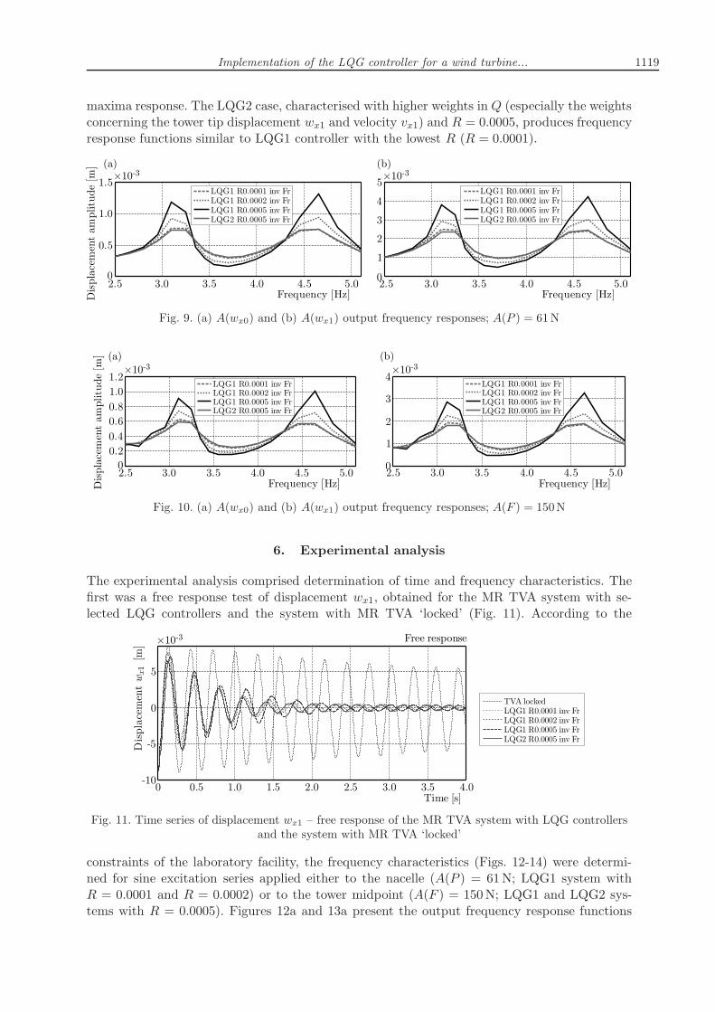
constraints of the laboratory facility, the frequency characteristics (Figs. 12-14) were determi-ned for sine excitation series applied either to the nacelle (A(P ) = 61N; LQG1 system withR = 0.0001 and R = 0.0002) or to the tower midpoint (A(F ) = 150N; LQG1 and LQG2 sys-tems with R = 0.0005). Figures 12a and 13a present the output frequency response functions
1120 M. Rosół, P. Martynowicz
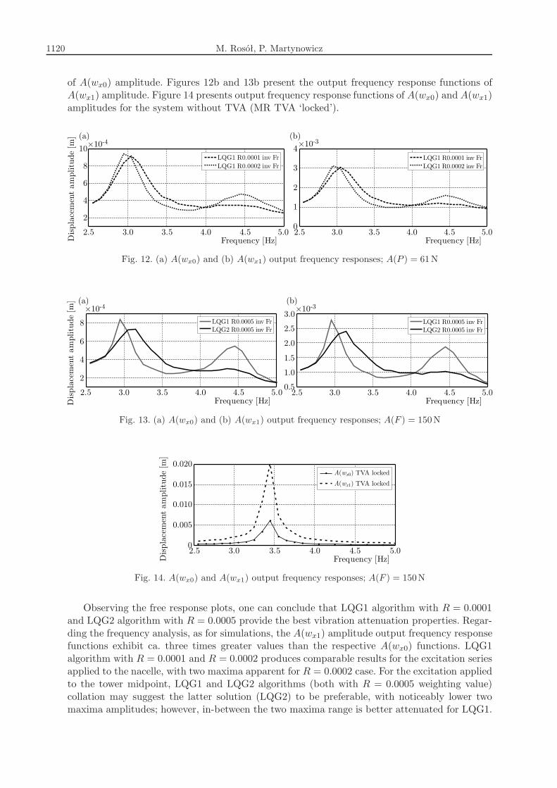
of A(wx0) amplitude. Figures 12b and 13b present the output frequency response functions ofA(wx1) amplitude. Figure 14 presents output frequency response functions of A(wx0) and A(wx1)amplitudes for the system without TVA (MR TVA ‘locked’).
Fig. 12. (a) A(wx0) and (b) A(wx1) output frequency responses; A(P ) = 61N
Fig. 13. (a) A(wx0) and (b) A(wx1) output frequency responses; A(F ) = 150N
Fig. 14. A(wx0) and A(wx1) output frequency responses; A(F ) = 150N
Observing the free response plots, one can conclude that LQG1 algorithm with R = 0.0001and LQG2 algorithm with R = 0.0005 provide the best vibration attenuation properties. Regar-ding the frequency analysis, as for simulations, the A(wx1) amplitude output frequency responsefunctions exhibit ca. three times greater values than the respective A(wx0) functions. LQG1algorithm with R = 0.0001 and R = 0.0002 produces comparable results for the excitation seriesapplied to the nacelle, with two maxima apparent for R = 0.0002 case. For the excitation appliedto the tower midpoint, LQG1 and LQG2 algorithms (both with R = 0.0005 weighting value)collation may suggest the latter solution (LQG2) to be preferable, with noticeably lower twomaxima amplitudes; however, in-between the two maxima range is better attenuated for LQG1.

Implementation of the LQG controller for a wind turbine... 1121
7. Conclusion
The obtained results prove the effectiveness of the LQG controller for the considered application.On the basis of the laboratory experiments, almost 10-fold reduction of the displacement wx1amplitude has been observed for the LQG2 system in comparison to the system without MRTVA (TVA ‘locked’) – see Figs. 13b and 14. Implementation of the LQG controller combines thebenefits of the LQR state feedback (including system linearization) with noise compensation bythe Kalman filter.
Based on the analyses, simulations and laboratory model measurements presented in thispaper, and considering force scale factor determination (Snamina and Martynowicz, 2014) incombination with the previous results (Snamina et al., 2014), direct calculation of demandedcontrol signal for a real-world full scale vibration reduction system/MR TVA is possible as well asthe calculation of the real-world wind turbine structural deflection and acceleration amplitudes,as for Vensys 82 plant regarded (Martynowicz, 2015).
Acknowledgment
This work has been supported by the Polish National Science Centre (Narodowe Centrum Nauki)
under project No. 2286/B/T02/2011/40.
References
1. Asai T., Spencer Jr. B.F., 2014, Model-free algorithms for seismic response control employingcontrollable dampers, Proceedings of the VI World Conference on Structural Control and Monito-ring, Barcelona
2. Asai T., Spencer Jr. B.F., Iemura H., Chang C.-M., 2013, Nature of seismic control forcein acceleration feedback, Structural Control and Health Monitoring, 20, 789-803
3. Athans M., 1971, The role and use of the stochastic linear-quadratic-Gaussian problem in controlsystem design, IEEE Transaction on Automatic Control, 16, 6, 529-552
4. Bak C., Bitsche R., Yde A., Kim T., Hansen M.H., Zahle F., Gaunaa M., Blasques J.,Dossing M., Wedel-Heinen J-J., Behrens T., 2012, Light rotor: the 10-MW reference windturbine, European Wind Energy Association Annual Event, 16-19.04, Copenhagen, Denmark
5. Butt U.A., Ishihara T., 2012, Seismic load evaluation of wind turbine support structures con-sidering low structural damping and soil structure interaction, European Wind Energy AssociationAnnual Event, 16-19.04, Copenhagen, Denmark
6. COMSOL AB, 2008, COMSOL Multiphysics MATLAB Interface Guide, COMSOL Version 3.5a,November
7. Den Hartog J.P., 1985, Mechanical Vibrations, Dover Publications, Mineola, NY
8. Dyke S.J., Spencer Jr. B.F., Sain M.K., Carlson J.D., 1996a, A new semi-active control de-vice for seismic response reduction, Proceedings of the 11th ASCE Engineering Mechanics SpecialtyConference, 886-889
9. Dyke S.J., Spencer Jr. B.F., Sain M.K., Carlson J.D., 1996b, Modeling and control ofmagnetorheological dampers for seismic response reduction, Smart Materials and Structures, 5, 5,565-575
10. Enevoldsen I., Mork K.J., 1996, Effects of vibration mass damper in a wind turbine tower,Mechanics of Structures and Machines, 24, 2, 155-187
11. Favoreel W., De Moor B., Gevers M., Van Overschee P., 1999, Closed loop model--free subspace-based LQG-design, Proceedings of the 7th Mediterranean Conference on Controland Automation (MED99), Haifa, Israel, 1926-1939

1122 M. Rosół, P. Martynowicz
12. Hansen M.H., Fuglsang P., Thomsen K., Knudsen T., 2012, Two methods for estimatingaeroelastic damping of operational wind turbine modes from experiments, European Wind EnergyAssociation Annual Event, 16-19.04, Copenhagen, Denmark
13. Hjalmarsson H., Gevers M., Gunnarsson S., Lequin O., 1998, Iterative feedback tuning:theory and applications, IEEE Control Systems Magazine, 18, 26-4.
14. Jain P., 2011, Wind Energy Engineering, McGraw-Hill
15. Jelavić M., Perić N., Petrović I., 2007, Damping of wind turbine tower oscillations throughrotor speed control, EVER Conference 2007, March 29-April 1, Monaco
16. Kawamura Y., 1998, Direct construction of LQ regulator based on orthogonalization of signals:Dynamical output feedback, Systems and Control Letters, 34, 1-9
17. Kciuk S., Martynowicz P., 2011, Special application magnetorheological valve numerical andexperimental analysis, [In:] Diffusion and Defect Data – Solid State Data. Pt. B, Solid State Phe-nomena, Vol. 177: Control Engineering in Materials Processing, 102-115
18. Kirkegaard P.H. et al., 2002, Semiactive vibration control of a wind turbine tower using anMR damper, Structural Dynamics EURODYN 2001, H. Grundmann (Edit.), CRC Press
19. Koo J.H., Ahmadian M., 2007, Qualitative analysis of magneto-rheological tuned vibration ab-sorbers: experimental approach, Journal of Intelligent Material Systems and Structures, 18
20. Łatas W., Martynowicz P., 2012, Modelling of vibration of the tower-nacelle system of a windpower plant with a dynamic damper (in Polish), Modelowanie Inżynierskie, 13, 44, 187-198
21. Ljung L., 2015, System Identification ToolboxTM. User’s Guide, MATLAB&Simulink R2015a,The MathWorks Inc., USA
22. Lord Rheonetic, 2002, MR Controllable Friction Damper RD-1097-01 Product Bulletin
23. Martynowicz P., 2014a, Development of laboratory model of wind turbine’s tower-nacelle systemwith magnetorheological tuned vibration absorber, Solid State Phenomena, 208, 40-51
24. Martynowicz P., 2014b, Wind turbine’s tower-nacelle model with magnetorheological tunedvibration absorber – numerical and experimental analysis, 6WCSCM: Proceedings of the 6th Editionof the World Conference of the International Association for Structural Control and Monitoirng(IACSM), 15-17.07, Barcelona, Spain
25. Martynowicz P., 2015, Vibration control of wind turbine tower-nacelle model withmagnetorheological tuned vibration absorber, Journal of Vibration and Control, doi:10.1177/1077546315591445
26. Martynowicz P., 2016, Study of vibration control using laboratory test rig of wind turbine tower--nacelle system with MR damper based tuned vibration absorber, Bulletin of the Polish Academyof Sciences Technical Sciences, 64, 2, 347359
27. Martynowicz P., Szydło Z., 2013, Wind turbine’s tower-nacelle model with magnetorheologicaltuned vibration absorber: the laboratory test rig, Proceedings of the 14th International CarpathianControl Conference (ICCC), 26-29.05, Rytro, Poland
28. Matachowski F., Martynowicz P., 2012, Analysis of dynamics of a wind power plant bymaking use of Comsol Multiphysics environment (in Polish), Modelowanie Inżynierskie, 13, 44,209-216
29. Namik H., and Stol K., 2011, Performance analysis of individual blade pitch control of offshorewind turbines on two floating platforms, Mechatronics, 21, 691-703
30. Oh S., Ishihara T., 2013, A study on structure parameters of an offshore wind turbine byexcitation test using active mass damper, EWEA Offshore, 19-21.11, Frankfurt
31. Rotea M.A., Lackner M.A., Saheba R., 2010, Active structural control of offshore windturbines, 48th AIAA Aerospace Sciences Meeting Including the New Horizons Forum and AerospaceExposition, 4-7.01, Orlando, Florida

Implementation of the LQG controller for a wind turbine... 1123
32. Sapiński B., Martynowicz P., 2005, Vibration control in a pitch-plane suspension model withMR shock absorbers, Journal of Theoretical and Applied Mechanics, 43, 3.
33. Sapiński B., Rosół M., 2007, MR damper performance for shock isolation, Journal of Theoreticaland Applied Mechanics, 45, 1, 133-146
34. Sapiński B., Rosół M., 2008, Autonomous control system for a 3 DOF pitch-plane suspensionmodel with MR shock absorbers, Computers and Structures, 86, 3/5, 379-385
35. Shan W., Shan M., 2012, Gain scheduling pitch control design for active tower damping and3p harmonic reduction, European Wind Energy Association Annual Event, 16-19.04, Copenhagen,Denmark
36. Singhal T., Harit Akshat, Vishwakarma D.N., 2012, Kalman filter implementation on anaccelerometer sensor data for three state estimation of a dynamic system, International Journal ofResearch in Engineering and Technology, 1, 6, ISSN 2277-4378
37. Snamina J., Martynowicz P., 2014,Prediction of characteristics of wind turbine’s tower-nacellesystem from investigation of its scaled model, 6WCSCM: Proceedings of the 6th Edition of the WorldConference of the International Association for Structural Control and Monitoirng (IACSM),15-17.07, Barcelona, Spain
38. Snamina J., Martynowicz P., Łatas W., 2014, Dynamic similarity of wind turbine’s Tower--nacelle system and its scaled model, Solid State Phenomena, 208, 29-39
39. Snamina J., Sapiński B., 2011, Energy balance in self-powered MR damper-based vibrationreduction system, Bulletin of the Polish Academy of Sciences Technical Sciences, 59, 1, 75-80
40. TMS, 2010, 60 Lbf Modal Shaker, The Modal Shop Inc.
41. Tsouroukdissian A., Carcangiu C.E., Pineda Amo I., Martin M., Fischer T., KuhnleB., Scheu M., 2011, Wind turbine tower load reduction using passive and semiactive dampers,European Wind Energy Association Annual Event, Brussels
42. Wang Y., Dyke S., 2013, Modal-based LQG for smart base isolation system design in seismicresponse control, Structural Control and Health Monitoring, 20, 5, 753-768
Manuscript received May 13, 2015; accepted for print January 27, 2016