Implementation of Software-Defined Radio Using USRP...
21
1 Implementation of Software-Defined Radio Using USRP Boards Written by Patrick Ellis & Scott Jaris Advisors Dr. In Soo Ahn & Dr. Yuefeng Lu May 10, 2011
Transcript of Implementation of Software-Defined Radio Using USRP...
1
Implementation of Software-Defined Radio
Using USRP Boards
Written by Patrick Ellis & Scott Jaris Advisors Dr. In Soo Ahn & Dr. Yuefeng Lu
May 10, 2011

2
Abstract Compared with hardware-based communication systems, software-defined radio (SDR) is a
communication system whose component functionalities are implemented in software running on
an embedded device. Due to its flexibility and re-configurability, the military has pushed the
SDR technology to become communication of the future, envisioning seamless communication
among various military units. Momentum has been built up in academia and industry to adopt the
SDR for implementing next generation communication systems. Universal Software Radio
Peripheral (USRP) is one of the most popular SDR platforms developed so far to support the
open-source GNU radio software package. In this project, usability and capabilities of the SDR
are studied using USRP boards. Different communication systems have been implemented on the
USRP platform and their functionalities have been validated.
Key words: Software-defined radio, USRP, GNU radio, Communication
Table of Contents
1. Introduction…………………………………………………………………………..….3
2. Software Defined Radio Design………………………………………………………...3
2.1 Equipment List ………………………………………………………………….......4
2.2 GNU Radio ………………………………………………………………….……….4
2.3 Simulation and Implementation of SDR……………………………………...……5
3. Discussion……………………………………………………………………………….13
4. Conclusion………………………………………………………………………………13
5. References…………………………… ………………… ………...…………....……...14

3
6. Appendix………………………………………………………………………………. .15
6.1 Installing the UHD and GNU Radio………………………………………………15
6.2 Deleting GNU Radio…………………………………………………………….….16
6.3 Updating GNU Radio……………………………………………………………....16
6.4 FM Radio Receiver Tutorial…………………………………………………….…16
6.5 Loading and Installing Firmware…………………………………………………20
6.6 List of Outside Tutorials…………………………………………………………...21
1. Introduction
There is a present day issue concerning the way people all over the world use technology to
communicate. Although the typical means for satisfying this need is by means of cell phones,
there are many forms of communication present in daily life. A radio is a general term for a
channel of communication and can be anything from a cell phone to a garage door opener. The
current method for implementing these devices is through fabrication in hardware, defined as
hardware radios. This form of communication device is thus made permanent by nature, creating
the need to replace components if any advancements or adjustments are to be imposed upon the
system. In today's fast paced world is quite often and is one motivation for implementing a new
technology to manage this situation. Another motivation originates from the increase in spectral
traffic; with the trend being that everyone own a cell phone with wireless internet that’s capable
of streaming live video, the amount of available bandwidth is diminishing. In addition, the need
for a world communication standard is a factor that further drives this urge. Software-defined
radio technology is the forefront of the solution to all three of these problems as well as the focus
of this project. The goal of the project is to showcase the benefits, usability, and capability of
SDR using GNU Radio and the USRP family of boards.
2. Software Defined Radio Design
In order to adequately portray the abilities of SDR, our main focus was to create multiple
different systems using various forms of modulation. These systems were debugged and tested
4
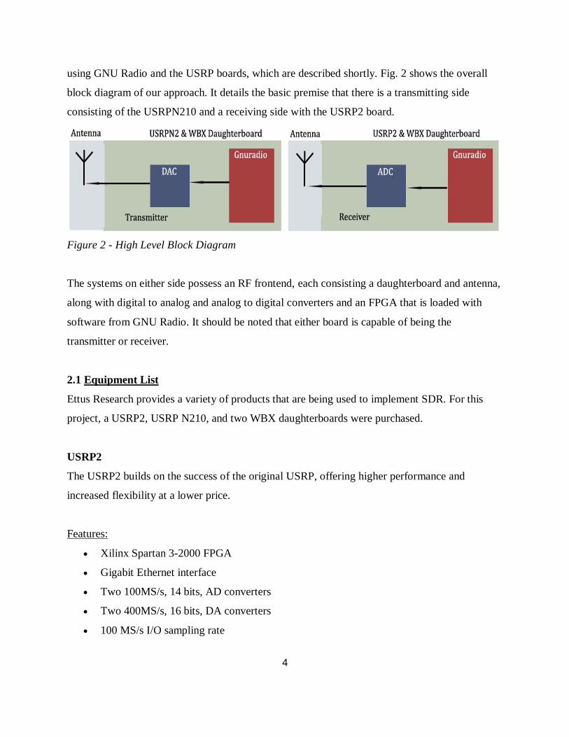
using GNU Radio and the USRP boards, which are described shortly. Fig. 2 shows the overall
block diagram of our approach. It details the basic premise that there is a transmitting side
consisting of the USRPN210 and a receiving side with the USRP2 board.
Figure 2 - High Level Block Diagram
The systems on either side possess an RF frontend, each consisting a daughterboard and antenna,
along with digital to analog and analog to digital converters and an FPGA that is loaded with
software from GNU Radio. It should be noted that either board is capable of being the
transmitter or receiver.
2.1 Equipment List
Ettus Research provides a variety of products that are being used to implement SDR. For this
project, a USRP2, USRP N210, and two WBX daughterboards were purchased.
USRP2
The USRP2 builds on the success of the original USRP, offering higher performance and
increased flexibility at a lower price.
Features:
Xilinx Spartan 3-2000 FPGA
Gigabit Ethernet interface
Two 100MS/s, 14 bits, AD converters
Two 400MS/s, 16 bits, DA converters
100 MS/s I/O sampling rate

5
USRP N210
The USRP N210 was released shortly after the purchase of the USRP2 and offers even higher
performance and flexibility.
Features:
Compatible with the USRP2
Xilinx Spartan 3A-DSP3400 FPGA
Dual 100MS/s, 14 bits, A/D converters
Dual 400MS/s, 16 bits, D/A converters
100 MS/s I/O sampling rate
WBX Daughterboards
Ettus research offers many daughter boards with differing features. The daughter boards are
easily installed and available for almost any project. For particular needs of this project and with
future projects in mind, the WBX daughterboard was selected to be installed on each USRP
board. Some of the key features are shown below.
Features:
Frequency Range: 50 MHz to 2.2 GHz
Transmit Power: 30 to 100 mW
Dual synthesizers for independent TX and RX frequencies
30 MHz transmit and receive bandwidth
2.2 GNU Radio
GNU Radio is an open-source software development toolkit used for implementing SDR. It has
been developed for use with the USRP family of boards and contains the signal processing
blocks used to create the code. It is widely used in academic and commercial environments to
support wireless communications research as well as to implement real-world radio systems.
GNU Radio Companion (GRC) is the GUI that provides an interface with GNU Radio and the
signal processing blocks, allowing a system to be quickly constructed. This GUI also enables the
user a wide range of flexibility. Fig. 3 showcases the ability to utilize the GRC provided by GNU

6
Radio to explore and understand a wide range of functionalities. For instance, Fig. 3
demonstrates how powerful this technology can be; each block is representative of a module that
can be chosen as desired to construct more complex blocks. This feature enables the addition of a
specialized features or mixing and match of functionalities to best suit the user’s design.
Figure 3 - Expanded system in GNU Radio Companion
Fig. 4 demonstrates how one could compress the many blocks in Fig. 3 with the same
functionality. GNU Radio allows the user the freedom to create both complex and simple
customized blocks that can be quickly added to any system.
Figure 4 - Compressed system in GNU Radio Companion
2.3 Simulation and implementation of SDR

7
A large amount of time was spent to overcome the steep learning curve that accompanied this
project. GNU Radio alone took a while to become familiar since any of the little documentation
that exists was scattered throughout the GNU Radio website and forums. Additionally, it was
critical to understand the USRP boards, Ubuntu, and digital communication theory quickly for
undertaking of the project. It can be overwhelming having to become familiar with so much at
one time and is the reason why we have created several tutorials to assist future projects in
shortening the steep learning curve. The tasks that were completed were the simulation of a
variety of systems, a test system, and the construction of an FM radio receiver and a complete
GMSK system. The problem encountered during the implementation is also discussed in this
report.
Simulation
Fig. 5 details the flowchart of a simulated DQPSK modulation scheme. Fig. 6 verifies the
success as the plots to the left detail the transmitted signal on top and the received signal on the
bottom – of which are identical. The constellation plot is to verify the DQPSK system. It should
be noted that this simulation was done without the introduction of noise; however, the system
was very resilient even when small values of noise were simulated and added to the system. The
receiver side still can decode the transmitted data correctly.

8
Figure 5 – SDR simulation: the DQPSK system
Figure 6 –Left: Transmitted signal and Received signal. Right: The constellation plot of
receiver
To further portray the usefulness of the USRP boards for SDR design, two communication
systems were implemented; the first being an FM radio receiver using a single USRP board, and
the second as a GMSK communication system using one USRP board as the transmitter and
another as the receiver.
FM Radio Receiver
Figure 7 shows the constructed system. The frequencies are read in from the USRP source, fed
to an FIR filter, demodulated with a phase-locked loop, and then resampled to a frequency
compatible with our sound card. The ability to “change stations” was done using a variable
slider that changed the center frequency of the UHD: USRP Source block. Fine tuning could also
be done using a slider bar to change the center frequency of the Frequency Xlating FIR Filter.
Figure 8 shows the FFT plot of the received signal. The FFT spectrum shows a square of
frequencies that are allowed in (stipulated by the FIR filter) and the slightly raised signal within
the square is in fact the radio station’s content. The Frequency Xlating FIR Filter taps were
contained in the variable ‘filter_taps’, and were created using the function

9
firdes.low_pass(1,samp_rate,200e3,1e3). This function creates taps based on a low pass filter
with sampling rate samp_rate, cutoff frequency 200k, and transition BW 1k. RF gains and audio
gains could also be adjusted using slider bars. The results of this FM receiver allowed us to listen
to multiple radio stations with acceptable to exceptional quality. The ability to add more radio
stations or add quality required meticulous manipulation of gains that we did not dedicate our
time to, but instead invested it to the completion of a modulated communication system.
Figure 7 - FM Radio Rx System

10
Figure 8 - Received Spectrum of FM Receiver
GMSK System
The original plan was to design DQPSK system, however, we ran into an issue while attempting
to transmit wirelessly between the two boards that occurred on the receiving side. Upon
troubleshooting, we determined that there was in fact data being presented to the packet decoder
block, but there was no output. This narrowed the problem area to either the packet decoder or a
transmission problem. With much debugging and no luck, we turn to a different type of
modulation scheme.
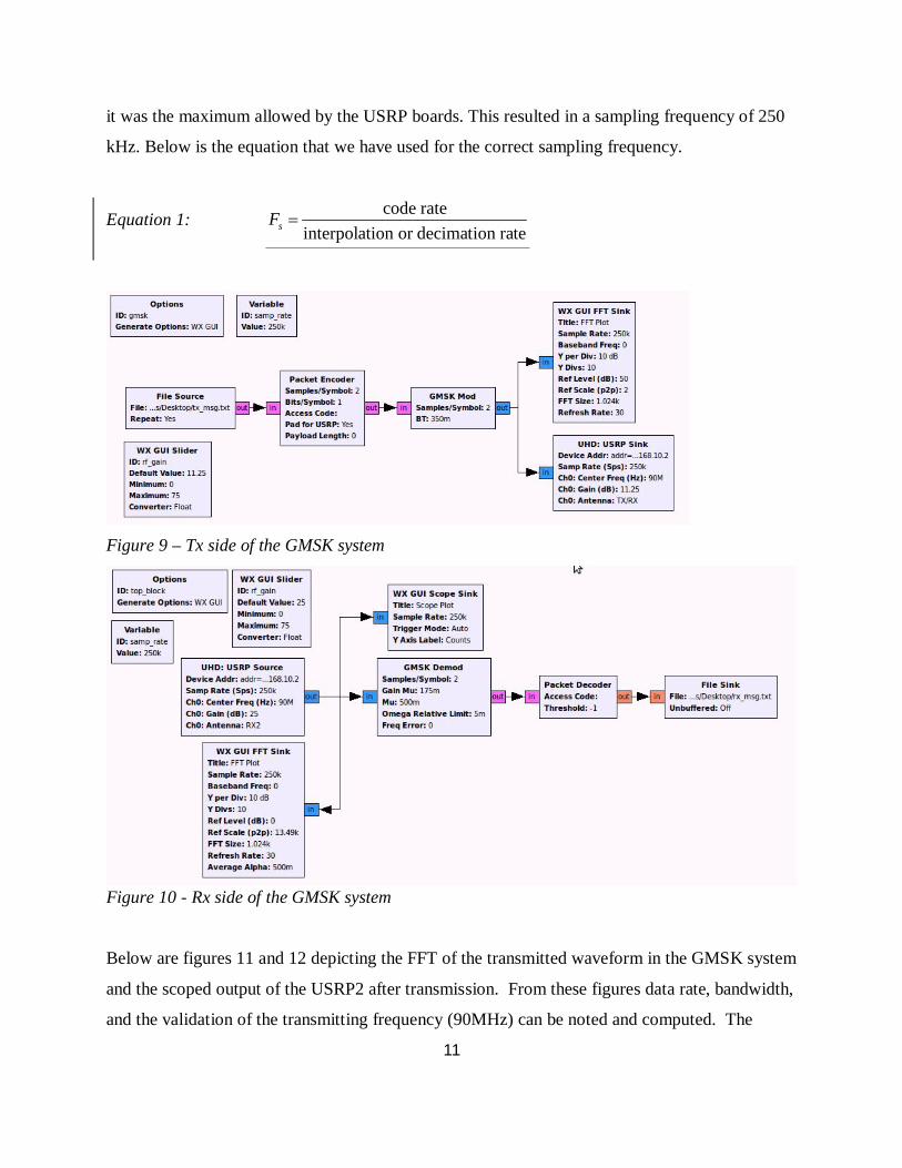
Figures 8 and 9 below are the transmitter and receiver sides of the GMSK communication
system respectively. We were able to perfectly demonstrate the sending of text files with very
few errors. The RF gains of the UHD: USRP Source and Sink blocks were determined by using
fine tuning with slider bars and observing the received spectrum. The completion of this system
raises hopes of addition of other communication system; however, will require research into
differences that exist internally within the blocks that allow the GMSK system to have success
while the others do not. Something important we observed was that the sampling frequency in
fact controls the interpolation/decimation rate taking place inside the USRP Systems when the
sampling frequency was varied. We selected the interpolation rate to be 400 for convenience, as
11
it was the maximum allowed by the USRP boards. This resulted in a sampling frequency of 250
kHz. Below is the equation that we have used for the correct sampling frequency.
Equation 1: code rateinterpolation or decimation ratesF
Figure 9 – Tx side of the GMSK system
Figure 10 - Rx side of the GMSK system
Below are figures 11 and 12 depicting the FFT of the transmitted waveform in the GMSK system
and the scoped output of the USRP2 after transmission. From these figures data rate, bandwidth,
and the validation of the transmitting frequency (90MHz) can be noted and computed. The

12
transmission bandwidth based on figure 11 is 180 kHz, and our calculated was 168750 Hz.
Below is the equation for bandwidth that we used.
Equation 2: 1 122
BWT T
Figure 11 – TX FFT of the GMSK system
Figure 12 – Spectrum of TX Signal on Oscilloscope

13
The success of this system added a valuable debugging experience as we attempted to
troubleshoot the issues of interfacing between demodulation blocks and the packet decoder. The
results show that the error did not lie within the packet decoder, but instead was something
within the DQPSK Demod block.
3. Discussion
The results of this project portray the flexibility and benefits of SDR by demonstrating that
completely different systems can be implemented on a single platform simply by changing code.
Additionally, it can be seen how much freedom is given when designing a system by allowing
the user to create a customized block if desired. Also, the fact that the signal processing is being
done in software provides the ability to make decisions not possible in hardware by including
case statements, or other programming operations.
With these results, a good deal of possible future work can be proposed.
1. Investigate differences in modulation schemes – why does the GMSK system work but
the DQPSK does not?
2. Write blocks for coding schemes currently unavailable (Ex. Turbo Code) and compare,
using SNR and BER measurements, with other forms currently provided by GNU Radio.
3. Complete the 16QAM block by creating the code for the demodulator portion.
4. Begin to add a more cognitive aspect by creating a system that can change modulation
schemes or some form of coding depending on the current SNR or BER being measured.
4. Conclusion
Software-defined radio has clear advantages over traditional hardware radio. Momentum has
been built up in academia and industry to adopt the SDR for implementing next generation
communication systems. As demonstrated by this project, the USRP in combination with the
GNU Radio software toolkit provides a strong base for this type of technology to be further
developed and applied for commercial applications. The possibilities are endless and it will be
interesting to see how far this technology will advance in the next 10 years.

14
5. References
Blossom, Eric, Johnathan Corgan, Matt Ettus, and Tom Rondeau. GNU Radio. 2006. Web. 27
Feb. 2011.
Brannon, Brad. Software Defined Radio. Analog Devices, Inc., 2008. Web. 24 Mar. 2011.
Liu, Dake, Anders Nilsson, Eric Tell, Di Wu, Johan Eilert. “Bridging Dream and Reality:
Programmable Baseband Processors for Software-Defined Radio.” IEEE Communications
Magazine 47.9 (2009): 134-140. IEEE. Web. 24 Mar. 2011.
McHale, John. “SDR: A Spectrum of Possibilities.” Military & Aerospace Technology 20.10
(2009): 32-39. Academic Search Premiere. Web. 27 Feb. 2011.
McHale, John. "SDR: Here, There, and Everywhere." Military & Aerospace Technology 19.10
(2008): 14-20. Academic Search Premiere. Web. 23 Mar. 2011.
Ulversøy, Tore. “Software Defined Radio: Challenges and Opportunities.” IEEE
Communications Surveys & Tutorials 12.4 (2010): 531-550. IEEE. Web. 24 Mar. 2011.

15
6. Appendix
6.1 Installing the UHD and GNU Radio
1. Install Ubuntu 10.04 Lucid
2. Open terminal
#Install the dependecies for GNU Radio on Ubuntu 10.04:
sudo apt-get -y install libfontconfig1-dev libxrender-dev libpulse-dev swig
g++ automake autoconf libtool python-dev libfftw3-dev \
libcppunit-dev libboost-all-dev libusb-dev fort77 sdcc sdcc-libraries \
libsdl1.2-dev python-wxgtk2.8 git-core guile-1.8-dev \
libqt4-dev python-numpy ccache python-opengl libgsl0-dev \
python-cheetah python-lxml doxygen qt4-dev-tools \
libqwt5-qt4-dev libqwtplot3d-qt4-dev pyqt4-dev-tools python-qwt5-qt4
3. #Install git and cmake:
sudo apt-get install git-core cmake
4. #Download and install UHD from git:
git clone git://code.ettus.com/ettus/uhd.git
cd uhd/host
mkdir build
cd build
cmake ../
make
make test
sudo make install
#Check where your path is with "find |grep libuhd"
export LD_LIBRARY_PATH=$LD_LIBRARY_PATH:/usr/local/lib
5. #Download and install GNU Radio from git:
git clone http://gnuradio.org/git/gnuradio.git
cd gnuradio
git branch --track next origin/next

16
git checkout next
git branch #Checks if you have correct path
export PKG_CONFIG_PATH=/usr/local/lib/pkgconfig:${PKG_CONFIG_PATH}
./bootstrap
./configure --enable-gr-uhd
make
make check
sudo make install
6. #If you cannot find the device, perform these commands.
Sudo ldconfig
Sudo ifconfig eth# 192.168.10.1
6.2 Deleting GNU Radio
1. cd uhd/host/build/gnuradio
2. sudo make uninstall
3. git clean -d -x –f
4. Delete UHD folder
5. Empty Trash Bin
6. Reinstall Gnuradio
7. Say a Prayer
6.3 Updating GNU Radio
1. cd uhd/host/build/gnuradio
2. get pull
6.4 FM Radio Receiver Tutorial
Introduction:
GNU Radio is an open source signal processing software package that is used to implement
software defined radio. This package is designed to be used in parallel with Universal Software
Radio Peripheral products created by Ettus Research. Not much documentation exists for

17
beginners looking to start exploring this technology. These instructions, which double as a
tutorial, give a step by step procedure to construct a functioning software-defined FM receiver
using GNU Radio Companion. They assume that the reader has a functioning computer running
on the Ubuntu 10.04 operating system that has the most current, UHD version of GNU Radio
properly installed.
Theory of operation:
Typical FM receivers are constructed entirely using hardware that must be fabricated in a plant.
This procedure will demonstrate the power of software defined radio and how easy it is to use. A
good background in Communication Theory would provide for better understanding of this
procedure, however, these instructions are written so that such is not required to complete the
task at hand.
List of equipment:
1. USRP2 or USRP N210 board with installed UHD firmware, image file, and daughterboard
that is in the FM frequency range (WBX for example)
2. Ethernet cable, antenna attachment, power cord
3. Speakers
Procedure:
1. Connect the USRP board to the computer using the Ethernet cable.
2. Attach the antenna to the receiver end of the daughterboard and power up the board by simply
plugging in the power cord.
3. Assign the location of the Ethernet cable to the address of the board by opening a command
window and entering:
sudo ldconfig
sudo ifconfig eth0 192.168.10.1
Note: You will have to use your administrative password when using the sudo command.
4. Check to see if the location is set properly by next entering into the command window:

18
sudo uhd_find_devices. This should return the location of the device. If it returns that no devices
were found, repeat step 3.
5. Open another command terminal and run GNU Radio Companion by entering the command:
sudo gnuradio-companion.
6. Add the necessary blocks from the libraries on the right side of the screen and arrange them as
shown in figure A1. (Most should be self explanatory as to which menu they are under).
7. Open the parameter window for the Audio sink by double clicking on the block.
8. Change the number of inputs to 2.
9. Match the data types for each block, corresponding with figure A2, making the selection in the
parameter window. A blue tab represents complex and orange represents float.
10. Make the connections shown by clicking on the tabs marked ‘in’ and ‘out’ on the appropriate
blocks.
11. Set up parameters as shown in figure A2 by opening each parameter window. Parameters that
cannot be directly determined from the figure are listed as follows.
a. Enter addr=192.168.10.2 for ‘Device Addr’ in the UHD: USRP Source.
b. Enter firdes.low_pass(1,samp_rate,100e3,1e3) for the Value in the Variable block with ID
filter_taps.
c. Enter rf_gain and usrp_freq in Ch0: Gain and Ch0: Center Freq parameters respectively in
the USRP Source block.
d. Enter xlate_freq in the Center Frequency parameter of the FIR Filter
e. Enter af_gain in Constant parameter for both Multiply Const blocks
12. Compile the program by clicking the icon. If there is an error, double check all connections,
parameters, and data types of the blocks.
13. Execute the flow graph buy clicking the icon. A graphic should appear similar to the one in
figure A3. If it is blank, click on the auto scale button to bring the FFT into view.
14. Tune into any of your local FM stations using the usrp_freq slider bar. Finer tuning can be
done using the xlate_tune slider bar. Volume can also be adjusted using the rf_gain and af_gain
slider bars.

19
Figure A1 – Blocks to be added in Step 6
Figure A2 - Complete flowgraph with appropriate connections, data types, and parameters as
mentioned in steps 9, 10, and 11

20
Figure A3 – Spectrum plot from the FFT sink showing the filtered frequency range being
received
Conclusion:
Having completed a functioning FM receiver, you should now be more comfortable working
with GNU Radio Companion and the USRP boards and hopefully are beginning to understand
the flexibility and potential of software defined radio technology.
Tutorial on how to load firmware and fpga image for usrpn210
6.5 Loading and Installing Firmware
Tutorial on how to load firmware and fpga image for usrpn210
Link for firmware:
http://www.ettus.com/downloads/uhd_images/UHD-images-most-recent/
sudo ldconfig
sudo ifconfig eth0 192.168.10.1
sudo apt-get install python python-tk idle python-pmw python-imaging
sudo /home/pellis/uhd/host/utils/usrp_n2xx_net_burner_gui.py

21
Tutorial on how to load firmware and fpga image for usrp2
sudo apt-get install python python-tk idle python-pmw python-imaging cd (where
card_burner.py is)
sudo ./usrp2_card_burner.py --dev=/dev/sdd –
fpga=/home/pellis/Desktop/firmware/images/usrp2_fpga.bin
sudo ./usrp2_card_burner.py --dev=/dev/sdd –
fw=/home/pellis/Desktop/firmware/images/usrp2_fw.bin
6.6 List of Outside Tutorials
For Python:
1.http://gnuradio.org/redmine/wiki/gnuradio/TutorialsWritePythonApplications
2. www.snowymtn.ca/GNURadio/GNURAdioDoc-5.pdf
For GNU Radio in General:
1. nms.csail.mit.edu/6.829-f06/projects/grace_slides.pdf
2. http://radioware.nd.edu/documentation/basic-gnuradio/before-diving-into-gnuradio
3. http://radioware.nd.edu/documentation/basic-gnuradio/entering-the-world-of-gnu-
softwareradio
4. http://radioware.nd.edu/documentation/basic-gnuradio/graph-blocks-connecting
Writing Your Own Block
1. http://radioware.nd.edu/documentation/advanced-gnuradio/writing-a-signal-processingblock-
for-gnu-radio-part-i
2. http://radioware.nd.edu/documentation/advanced-gnuradio/writing-a-signal-processingblock-
for-gnu-radio-part-ii