
IMPLEMENTATION OF SEQUENTIAL DECIMAL MULTIPLIER
72
IMPLEMENTATION OF SEQUENTIAL DECIMAL MULTIPLIER A Thesis Submitted in Fulfillment of the Requirement for the Award of the Degree of MASTER OF TECHNOLOGY in VLSI Design Submitted By SONAL GUPTA 601562024 Under Supervision of Ms. Sakshi Assistant Professor, ECED ELECTRONICS AND COMMUNICATION ENGINEERING DEPARTMENT THAPAR UNIVERSITY, PATIALA, PUNJAB JUNE, 2017
Transcript of IMPLEMENTATION OF SEQUENTIAL DECIMAL MULTIPLIER

IMPLEMENTATION OF SEQUENTIAL DECIMAL
MULTIPLIER
A Thesis Submitted in Fulfillment of the Requirement for the Award of the Degree of
MASTER OF TECHNOLOGY
in VLSI Design
Submitted By
SONAL GUPTA
601562024
Under Supervision of
Ms. Sakshi
Assistant Professor, ECED
ELECTRONICS AND COMMUNICATION ENGINEERING DEPARTMENT
THAPAR UNIVERSITY, PATIALA, PUNJAB
JUNE, 2017

Scanned by CamScanner

iv
ACKNOWLEDGEMENT
It is my proud privilege to acknowledge and extend my gratitude to several persons who
helped me directly or indirectly in completion of this report. I express my heart full
indebtedness and owe a deep sense of gratitude to my teacher and my faculty guide Ms.
Sakshi, Assistant Professor, ECED, for her sincere guidance and support with
encouragement to go ahead.
I am also thankful to Dr. Alpana Agarwal, Associate Professor and Head, ECED, for
providing me with the adequate infrastructure for carrying out the work. I am also thankful to
Dr. Hemdutt Joshi, Associate Professor and P.G. Coordinator, ECED, and Dr. Anil
Arora, Assistant Professor and Program Coordinator, ECED, for the motivation and
inspiration and that triggered me for the work.
The study has indeed helped me to explore knowledge and avenues related to my topic and I
am sure it will help me in my future.
Sonal Gupta
Roll No.- 601562024

v
ABSTRACT
Multiplication is the most important operation among all the four arithmetic operations
during the last decade in various fields which is in the top list of research. Decimal
multiplication is gaining very high popularity in recent years in the fields like analysis of
finance, banking, income tax department, insurance and many more such fields. The
hardware implementation of this has become a very important and interesting topic of
research. There are a number of multipliers such as serial multiplier, parallel decimal
multiplier, booth multiplier, Wallace tree multiplier, combinational decimal multiplier,
sequential decimal multiplier, array multiplier and sequential multiplier. Each multiplier has
its own advantages and disadvantages. Among all these multipliers, the implementation of
parallel decimal multiplier is considered to be the hardest because of its high cost of area. The
processor industries have implemented a new version of multipliers which is sequential
decimal multipliers so as to reduce this high implementation cost. The problem with this
sequential decimal multiplier is its high latency. In the reported work, the focus is to generate
a sequential decimal multiplier with lowest possible area, delay and power consumption. The
BCD-8421 coding mechanism is used to generate easy multiples and partial products.

vi
TABLE OF CONTENTS
Pre-Pages…………………………………………..………………………………………i-xiv
Declaration……………………………………..……………………………………………...ii
Certificate……………………………...……………………………………………………...iii
Acknowledgement………………………………………..…………………………………...iv
Abstract………………….………………………………………………………………….…v
Table of Contents…………………………………………………….…………………….…vi
List of Figures………………………………………………………………………………..xii
List of Tables……………...…………………………………………………………………xiv
List of Glossary………………………………..……………………………………………..xv
Chapter 1 Introduction…………………………………………………………………..…1-10
1.1 Motivation……………………………………………………………………......1
1.1.1 Higher Demand……………………………………………………………1
1.2 Multipliers………………………………………………………………………..2
1.3 Types of Multipliers…………………………………………………………...…2
1.3.1 Serial Multiplier……………………………………………………...……4

vii
1.3.2 Parallel Multiplier……………………………………………………...….4
1.3.3 Shift and Add Multiplier………………………………………………….5
1.3.4 Combinational Multiplier…………………………………………………5
1.3.5 Booth Multiplier……………………………………………………….….5
1.3.6 Modified Booth Multiplier……………………………………………..…5
1.3.7 Wallace Multiplier……………………………………………………..….6
1.3.8 Array Multiplier………………………………………………...…………6
1.3.9 Sequential Decimal Multiplier…………………………………………….6
1.4 Stages of Multiplication……………………………………………………….....7
1.4.1Partial Product Generation………………………………………………....7
1.4.2 Partial Product Accumulation…………………………………………......7
1.4.3 Carry-Propagate Addition………………………………………………....8
1.5 Importance of Multipliers……………………………………………………..…8
1.5.1 Public Investment………………………………………………………....8
1.5.2 Trade Cycle Analysis……………………………………………………...8

viii
1.5.3 Importance in Investments………………………………………………..9
1.5.4 Development of Economic Policies……………………………………….9
1.5.5 Equality between Saving and Investment………………………………....9
1.6 Organization of Thesis……………………………..…………………...………..9
Chapter 2 Literature Survey……………………………………………………………....11-17
2.1 Introduction to Decimal Multiplication……………………………….………..11
2.2 Decimal Parallel Multiplication………………………………………………...13
2.3 Sequential Decimal Multiplication..……………………………………………16
Chapter 3 Multipliers…………………………………………..…………………………18-35
3.1 Type of Multipliers……………………………………………………………..19
3.1.1 Serial Multiplier…………………………………………………….……19
3.1.2 Parallel Multiplier………………………………………………………..21
3.1.3 Shift and Add Multiplier…………………………………………………22
3.1.4 Array Multiplier……………………………………………………….....22
3.1.5 Booth Multiplier………………………………………………………....22

ix
3.1.6 Modified Booth Multiplier………………………………………………27
3.1.7 Combinational Multiplier……………………………………………..…30
3.1.8 Wallace Multiplier…………………………………………………….....31
3.1.9 Sequential Decimal Multiplier……………………………………..……32
3.2 Stages of Multiplication…………..………………………………………..…..33
3.2.1 Partial Product Generation…………………………………………..…..34
3.2.2 Partial Product Accumulation………………………………………..….34
3.2.3 Carry-Propagate Addition…………………………………………….…35
Chapter 4 Research Methodology and Structure………………………………………....36-44
4.1 The Proposed Sequential Decimal Multiplier…………………………………..36
4.2 Tool and Language Used………………………………………………….…....37
4.3 Algorithm and Flowchart of the Proposed Sequential Decimal Multiplier…….38
4.3.1 Algorithm of the Proposed Sequential Decimal Multiplier………….…..38
4.3.2 Flowchart of the Proposed Sequential Decimal Multiplier……………...40
Chapter 5 Simulation and Synthesis Results……………………………………………..42-46

x
5.1 32-Bit Sequential Decimal Multiplier……………………………………..……42
5.1.1 Simulation Results……………………………………………………….42
5.1.2 Synthesis Report………………………………………………….……...44
5.1.3 Power Consumption Report………………………………………..….…44
5.1.4 Timing Summary……………………………………………………..….45
5.1.5 Performance Report…………………………………………………..….45
Chapter 6 Conclusion and Future Scope…………………………………………………..…47
6.1 Concluding Remarks………………………………………...………………….47
6.2 Future Scope………………………………………………………...………….47
References…………………………………………………………………………...……48-51
Originality Report

xi
LIST OF FIGURES
Figure 1.1 Types of Multipliers……………………………………………………..………...4
Figure 3.1 4-Bit Serial Multiplier………………………………………………………..…..20
Figure 3.2 Parallel Multiplier……………………………………………………………..….21
Figure 3.3 Shift and Add Multiplier……………………………………………….……..….23
Figure 3.4 4*4 Bit Multiplication………………………………………………….…………23
Figure 3.5 32×32 Bit Array Multiplier…………………………………………….…………24
Figure 3.6 Architecture of Booth Multiplier…………………………………………………25
Figure 3.7 Table for Booth Algorithm……………………………………………………….27
Figure 3.8 3 Bit Pairing using Overlap Technique…………………………………………...28
Figure 3.9 32×32 Bit Modified Booth Multiplier……………………………...…………….30
Figure 3.10 Combinational Multiplier Algorithm……………………………………………31
Figure 3.11 32×32 Bit Wallace Tree Multiplier’s Block Diagram…………………………..32
Figure 3.12 Block Diagram of Sequential Multiplier……………………...…………………33
Figure 3.13 Generation of Easy Multiples………………………………………………..….34
Figure 3.14 3:2 Carry Save Adder Generic Scheme………………………………………....35
xii
Figure 4.1 Flowchart for the Proposed Sequential Decimal Multiplier……………………...41
Figure 5.1(a) Simulation Result……………………………………………………………...43
Figure 5.1(b) Simulation Result……………………………………………………………...43
Figure 5.2 Synthesis Report………………………………………………………………….44
Figure 5.3 Power Consumption Report………………………………………………………45
Figure 5.4 Timing Summary…………………………………………………………………45

xiii
LIST OF TABLES
Table 3.1 Recoding Table for Modified Booth Algorithm………………….………………29
Table 5.1 Performance Report Table………………………………………………………..46
xiv
LIST OF ABBREVIATIONS
BCD – Binary Coded Decimal
BFP- Binary Floating Point
CDM- Combinational Decimal Multiplier
CLA – Carry-Look-Ahead
CMOS- Complimentary Metal Oxide Semiconductor
DFP- Decimal Floating-Point
DSP - Digital Signal Processing
FPGA – Field Programmable Gate Array
ISE – Integrated Synthesis Environment
LUTs – Lookup Tables
MAC- Multiplier and Accumulator
MBA- Modified Booth’s Algorithm
PDAM- Parallel Decimal Array Multiplier
PPG- Partial Product Generation
PPR- Partial Product Reduction

xv
RTL - Register-Transfer Level
VHDL - VHSIC Hardware Description Language
VHSIC - Very High Speed Integrated Circuit

1
CHAPTER-1
INTRODUCTION
The hardware implementation of decimal multiplier is continuously increasing at a rapid rate
during the last decade. This continuous growth of the decimal multiplier is due to its ability to
alternate the human capabilities which binary multiplier could not possibly perform well. A
decimal multiplier requires larger number of multiplicand multiples than a binary multiplier
which makes its designing more complicated. Binary multiplication is much simpler than the
decimal multiplication. The challenges are due to the complexity involved in the decimal
number system which comes into issue during hardware implementation.
In today’s DSP applications and internet-based applications, the role of multipliers is
quite significant. As the technology in advancing, the researchers are trying to develop
multipliers in which they can achieve at least one of the following design targets- low area,
low delay and low power consumption.
1.1 MOTIVATION
1.1.1 Higher Demand
Nowadays the IC technology is going more difficult in terms of designing and its
performance analysis. A design which is fast having comparatively lower power
consumption and also smaller area is best fit to the modern electrical and electronic
designs. Continuous advancements and developments in the microelectronic design
technology make suitable use of energy, encrypt the data carefully, communicate
relevant information with more resolute determination, etc. In particular sense, in
order to attain the basic demands and necessities of various applications, generally
portable applications, many of these technological application demands for lowest
possible power consumption. In such application systems, a multiplier unit is the most
basic and fundamental arithmetic unit which is widely used in circuits and for which
the process of multiplication should best optimized. Multipliers generally have large
latency, large area and consume significant amount of power. Hence designing a
multiplier with low power has become a crucial part in VLSI system design. Now

2
with the increase in technology, everyday new methods and approaches are being
grown to design low-power multipliers at various levels such as technical, circuit,
physical and logic levels. Since the multiplier is generally considered as one of the
slowest unit in any system, the performance of a system is ultimately determined by
the multiplier’s performance. Moreover, multipliers consume the most of the area in
any design. Therefore, to attain optimization between a multiplier’s area and speed is
a major and important designing problem in today’s scenario. Also, area and speed
are highly conflicting parameters thus if we improve speed of any unit it results in
greater areas and vice-versa. Also the parameters such as area and power consumption
of any circuit are linearly related and dependent on one another. So as to reduce
power and area a compromise has to be done with speed of the circuit.
A large number of computer arithmetic algorithms may be used to implement
a digital multiplier. Most of the techniques generate a set of partial products, and then
add them together, once they undergo shifting. The multiplier’s speed can be
increased on significant decrement in the generated of partial products.
1.2 MULTIPLIERS
Multipliers are one of the most important elements of many systems with high performance
such as microprocessors, FIR filter, DSP, etc. Multiplier is considered as the slowest element
thus it determines the overall performance of the system. Above all, it consumes high area.
Hence, major design issue is to obtain optimization between the multiplier’s speed and area.
Larger area is an effect of improvement in the speed, therefore making area and speed a
conflicting constraints.
With the increasing level of complexities and device integration of microelectronic
circuits, power dissipation reduction has also come up as a primary design goal.
1.3 TYPES OF MULTIPLIERS
There are a multiple type of multipliers discussed in this section. The most general
multiplication method is based on the “add and shift” algorithm. The various types of
multipliers are mentioned in the following points-

3
Serial multiplier
Parallel multiplier
Shift and Add multiplier
Combinational multiplier
Wallace multiplier
Modified Wallace multiplier
Array multiplier
Booth multiplier
Modified Booth multiplier
Sequential Decimal multiplier

4
Fig.1.1: Types of Multipliers
1.3.1 Serial Multiplier
A serial multiplier is used in applications where the speed of the multiplication
operation is ignored and is not of prime concern. It is used where the main
concentration is on saving the area and power.
1.3.2 Parallel Multiplier
The parallel multiplier came up with the advantage of high speed. Most of the binary
multiplying units make use of parallel mechanism to build multiplier which thereafter
became popular for the decimal multiplication as well to scale performance. In a
parallel decimal multiplier the multiplier’s overall performance is determined by the

5
number of partial products which are about to get added. Various algorithms were
introduced to lower down the count of different partial products being added. The
biggest disadvantage of this type of multiplier is that it introduces complexity in the
hardware circuit, which thereafter increases the overall area cost.
1.3.3 Shift and Add Multiplier
A multiplicand value is added and then accumulated, depending upon the multiplier’s
LSB. After each clock the value of multiplier gets right shifted by one bit and the
generated bit is then tested. Asynchronous circuits use this type of multiplication.
1.3.4 Combinational Multiplier
A combinational multiplier is used to multiply two signed or unsigned binary
numbers. In this, the multiplicand (i.e. Y) is multiplied with each individual bit of the
multiplier (i.e. X), the product is associated with the bit position in the multiplier, and
to get the final result the obtained product terms are then added. Binary multiplication
has the advantage that it can be achieved easily. If the multiplier bit is 1, then the
result of the multiplication will simply be the shifted form of the multiplicand and if it
is 0, then the result will simply be 0. The main drawback of combinational multiplier
is that it takes large area and is slow.
1.3.5 Booth Multiplier
Multiplication of two binary numbers in the representation of signed-2’s complement
is given by a booth multiplier. Andrew Donald Booth did the invention of booth
multiplier algorithm in 1950 at Birkbeck College in London. It is highly used in the
study of computer architecture.
1.3.6 Modified Booth Multiplier
The drawbacks of the radix-2 booth multiplication operation were overcome by radix-
4 Booth’s algorithm, commonly known as modified booth algorithm, which scans
string of three. It was mainly used to overcome the problem of slow speed of the
previous multiplier on making the number of partial products into half. This can be

6
achieved by avoiding the continuous shift and add operations on each column of the
multiplier term and multiplying by 0 or 1, simply multiplying ±1, ±2, or 0 by taking
every second column to obtain the final result. Based on the multiplier bits, the radix-
4 booth encoder performs the encoding operation. An overlapping technique will be
involved for this encoding in which three bits are compared at a time.
1.3.7 Wallace multiplier
Partial product generator is used to obtain partial products by multiplying each
individual bit of the multiplier (i.e. X) with that of the multiplicand (i.e. Y). Both the
multiplier and the multiplicand is of 32-bit, thus generate a total of 32 partial
products. A Wallace tree structure is used to add these partial products of a number of
4:2 compressors which increases its speed of accumulation. A carry- propagate adder
normally known as carry-look-ahead adder is used at the final stage which has the
sum and carry.
1.3.8 Array Multiplier
An array multiplier is a multiplication process has a regular structure. it involves the
procedure of repeated addition and shifting operations. The partial products are
created by carrying multiplication of each single multiplier (i.e. X) digit with the
multiplicand (i.e. Y). Then according to their bit sequences, the partial products are
shifted and then summed up. A normal carry-propagation adder is used for the
addition operation. Array multiplier comes with the advantage of least complexity,
but its biggest disadvantage is that it consumes high power. More number of digital
gates is required by an array multiplier which thereby increases the area cost.
1.3.9 Sequential Decimal Multiplier
The operation of sequential multiplier will begin with the start pulse and operands
will be contained by the data bus in two consecutive clock pulses. The operands here
are A and B. As it receives data the multiplication operation is performed and the final
result i.e. the product is again send to the data bus. Sequential realization of the

7
multipliers was done to overcome the high area cost problem. The biggest limitation
with them is their high latency.
1.4 STAGES OF MULTIPLICATION
Multiplication consists of these basic three stages:
Partial Product Generation
Partial Product Accumulation
Carry-propagate addition.
Decimal multiplication is considered as the most complex operation. Its complexity level is
mainly higher than the binary multiplication because of the following two reasons: the
decimal digits have higher range, which increases the number of multiples in the
multiplicand, thereby decreases the efficiency of decimal values represented in BCD–8421
coding mechanism, because only 9 out of the 16 possible 4–bit combinations can be
represented in BCD-8421 coding technique. Due to these reasons, the generation (i.e.
creation) and reduction (i.e. accumulation) of partial products is complicated.
1.4.1 Partial Product Generation
The partial products are generated easily by making use of the generated easy
multiples i.e. 2X, 4X, 5X. Easy multiples are generated so as to ignore the operation
on negative numbers.
1.4.2 Partial Product Accumulation
The direct approach of implementing the PPA is to join two of the partial products at
the same time, add them using an adder and repeat the process until the final result is
attained. If a single adder is used to perform all these operations, then this reduction
of partial product will consume only N- cycles which mean a total consumption of N-
mechanical delays if the relay adder is used.

8
1.4.3 Carry Propagate Addition
The basic usage of a carry save adder is to accumulate the partial products resulting in
the final sum and carry. It improves the speed of accumulation of the partial product
as it saves the carry and passes it to the next level of carry select adder. Therefore, the
adders in the same layer become independent of each other and can be executed
simultaneously. Hence the time required for the addition operation is reduced. The
carry save adder tree uses a one’s compliment based radix-2 modified booth algorithm
for partial product generation and accumulation. Accumulation is combined with a
carry save adder tree to compress the partial products.
1.5 IMPORTANCE OF MULTIPLIERS
Multipliers have their importance in both practical as well as theoretical point of view. They
have many applications in various fields such as finance, business, digital signal processing,
VLSI applications and many more. Apart from these areas, multipliers are highly used in
business as well as economic sectors. The importance of multipliers is given below-
1.5.1 Public Investment
There is a great importance of multipliers in public investments. Public investments
are much beneficial in situations like depression and unemployment because their
main motive is not on the profit. By increasing the employment level, the multipliers
indicate the importance of public investments.
1.5.2 Trade Cycle Analysis
The importance of multipliers is also seen while analyzing the trade cycle. It becomes
very easier for the developer to analyze trade cycle based on multipliers. Multipliers
estimate the increment in income with the result of increment in investment. Thus,
multipliers are of high importance in developing and composing new rising and
progressive policies, so that it can bring positive changes in the growth of economy
with the right pace.
9
1.5.3 Importance in Investments
A very important factor of economy is investment which is highly considered by
theory of multipliers. The proportionate increment and decrement in the income level
and employment level is ultimately depends upon the multipliers. This clearly
indicates that the increment and decrement in the level of income and employment is
completely based on the increase and decrease of the level of investment.
1.5.4 Development of Economic Policies
Every economic policy is based on the agenda of creation of situations which are full
of employments in the economic level. Therefore multipliers are of great importance
and use for the policy makers to compose and formulate the economic policies of their
country. This increases the chances of creating the situation of full employment and
thereby leads to increment in the employment rate of the country which ultimately is
required for growth and development.
1.5.5 Equality between Saving and Investment
Multipliers are also important in maintaining equality between the saving and
investment. The increment or decrement in the investment directly affects the level of
income. Increase in the level of income will surely bring equality between the saving
and investment.
1.6 ORGANIZATION OF THESIS
The thesis is organized as follows:
Chapter 1 presents a brief overview of multipliers, their previous discoveries along with
their advantages and limitations.
Chapter 2 gives a brief description of the research that has been reported in literature in the
field of different types of multipliers and their related work.

10
Chapter 3 includes the basic concept of sequential decimal multiplier, its structure and basic
operation. It also describes its advantages over other multiplying units.
Chapter 4 presents the implementation of the sequential decimal multiplier along with its
simulated results.
Chapter 5 describes the proposed sequential decimal multiplier and the simulation results of
it have been presented. The results have been compared with the previous work available in
literature and compared on various aspects.
Chapter 6 concludes the report while also mentioning the future possibilities to carry
forward the research in this domain.

11
CHAPTER-2
LITERATURE SURVEY
Many authors have presented their views on the related topics of the decimal multiplication
operation. Some of them are as follows-
2.1 INTRODUCTION TO DECIMAL MULTIPLICATION
M. S. Schmookler, et.al., 1971[3], have described a decimal adder of 8-bits which requires
less number of logic circuits as compared to the adders. The adders need involvement of
decimal correction. Decimal correction includes delay of two extra logic levels. A 32-bit
binary adder, of the same width, when used for comparison purpose, for the same number of
logic levels the decimal adder needs almost 18% extra circuitry. Further they have added that
although a 32-bit binary adder has the same cost as that of the decimal adder, but it can be
designed with a delay of only 5 logic levels. They have finally concluded that there are a
variety of other decimal adders that can be designed based on the different principles.
Mark A. Erle, et.al., 2003[8], have presented two different architectures for decimal
multiplication with fixed-point numbers. These designs make use of carry-save addition so as
to decrease the delay of the critical path. The first design presents a multiplier which saves a
reduced number of multiples of the multiplicand. The first design makes use of carry-save
adder also in some segments of the design. In this paper they have presented a justified
hardware description for decimal arithmetic and have also motivated for decimal
multiplication. They have given an opening stage design for a decimal multiplier. This design
introduces the concepts of decimal multiplication. It also mentions the issues related to the
decimal multiplication. The design is used to establish a fundamental baseline for the purpose
of comparison. Then they have analyzed and considered the limitations and disadvantages of
the initial design and have provided the best possible alternative solutions. They have also
shown another design of the decimal multiplier which has a number of notable and required
improvements to have an operating frequency which is significantly higher and which
ultimately has a lowered amount of worst-case delay. The design is such that it has (n + 1)
cycle of initial interval, where n is the multiplier operand’s significant number of digits. At

12
last, in order to reduce the average latency, several data dependent optimizations were also
described.
Kenney, R. D., et.al., 2004[9], have provided a motivation to implement decimal arithmetic
in hardware. They have presented a repetitive decimal multiplier. This decimal multiplier
works at relatively higher frequencies of clock. This type of multiplier is suitable for the
designs if the size of the operands is large. This multiplier makes use of a freshly new
representation for the intermediate products. This decimal representation is allowed for a very
high speed 2-stage multiplier design. An overloaded decimal representation is used to store
the intermediate products. This representation allows the use of BCD digits which invalid.
Decimal multipliers are implemented in Verilog language for a number of different digit
operands. The result of synthesis shows that the circuits work with the approximate frequency
of clock as 2 GHz if it is designed by making use of a 0.11 micron CMOS standard cell
library.
T. Lang, et.al, 2006[13], have presented a combinational multiplication unit for decimal
numbers which takes advantage of the pipelining technique so as to obtain the required
throughput. The implementation of the given multiplication unit was done in the standard
cell. This approach ultimately lower downs the number of pre-computations of the partial
products and also counters are used which discard the requirement of decimal equivalent
number. The implementation results clearly mentions that a combinational decimal
multiplication unit obtains high amount of optimization between delay and area as compared
to any other multiplication unit. Only multiplicand’s two and five multiples are required for
generation and creation of the partial products. Counters and radix-10 CSA was used for
accumulation purpose. Upon synthesis, the result of the overall delay caused by the operation
is 2.65 ns which can be easily pipelined so as to obtain the needed efficiency and throughput.
If compared to the radix-10 decimal sequential multiplication unit, it has lesser delay. The
proposed design is also compared to the double-precision multiplication unit for binary
numbers. It offers a delay double to that of binary multiplication unit with 50% greater area.
Michael J. Schulte, et.al, 2007[14], have presented a new design for multiplication of
decimal floating point numbers. This research work has provided a method to apply the
multiplication process on the floating-point decimal numbers which was earlier designed only
13
for the fixed-point decimals. There are a number of improvements in the design which was
earlier used for multiplication of fixed-point numbers like generation of exponent, generation
of sticky bit, intermediate bit shifting, rounding-off techniques and to detect and handle
exception. The delay in the critical path is reduced using decimal CSA. In order to provide
the estimated delay and area Verilog RTL model was used.
Tsen, et.al., 2009[17], have presented a design which is a combination of both BID and BFP
multiplication units. The design of the multiplier is such that it either operates on 64*64
binary-encoded DFP or 64*64 BFP numbers. The hardware resources such as design bocks,
decoder, rounding method and the encoder can be reused. It allows the sharing of hardware. It
has a significant effect on the delay and area values. A common algorithm for BFP
multiplication and rounding-off is used in the main algorithm. The main objective of this
proposed work was to explore the sharing of hardware for IEEE 754-2008 multiplication for
floating-point numbers.
Bozdas, et.al., 2012[23], have proposed a technique to search for the boundary conditions on
each single column sum of the n-digit PDAM. This PDAM is a multiplication approach on
the basis of CDM. At first, the solutions for these boundaries were found. These solutions are
obtained using the genetic algorithm. These boundaries were further applied in the binary
adder. They are also used in the binary to BCD converters. The area requirements of this type
of multiplier are large because the design has the presence of digit multiplication units. The
performance in terms of delay is increased by 8%.
2.2 DECIMAL PARALLEL MULTIPLICATION
Mark A. Erle, et.al., 2005[11], have described a novel approachable method for decimal
multiplication for fixed-point decimal numbers. This approach utilizes limited and restricted
range of signed-digits in the entire process of the multiplication. The multiplication process
involves generation and accumulation i.e. reduction of the partial products in a systematic
and well organized manner. An extremely simple recoding method was adopted to achieve a
representation which is in signed-magnitude format for the operands so as to achieve the
restricted range. It was then later shown that how the generation of the partial product
involves the recoded digits usage. The range for these recoded digits is in the range of −510 to
+510. For input digits the products are obtained if a simple combinational logic is used. The
14
range for input digits is 210 to 510. They have also described the relevant steps required to take
care of the signs of the input operands. This paper also describes the steps needed to detect
and handle the different cases in which the input digit is either 0 or 1. It also describes the
coding of the results obtained from the generation i.e. creation of the partial products logic. A
signed-digit adder is used to add the final result to the accumulated previous partial products’
sum. All the original characteristics of this paper include: 1) the approach used for recoding
the digits to a format which is in signed-magnitude form; 2) the decimal partial product
generation design; and, 3) the recoding of the partial products prior to send them to the signed
digit adder.
Paolo Montuschi, et.al., 2007[15], have introduced various techniques for implementation of
parallel decimal multiplier. BCD-4221 encoding is used in the algorithm adopted for addition
i.e. PPR operation. The area and delay requirements are met using this approach. This
approach offers the combined multiplication to take place for both binary and decimal
numbers. Three different methods were presented to generate the partial products with high
speed and efficiency. The PPG method’s complexity is highly reduced. Moreover the
technique allows the further use of traditional parallel multiplier with radix-4. The results
show that the proposed multiplier has quite significant area-delay values.
Jaberipur, et.al., 2009[16], have examined the previous two solutions and the effect of PPR
method on the design of the parallel decimal multiplier and selected the best possible
approach. A complete new PPG approach was generated and CSA technique is used to lower
down the effect of PPR technique. The multiplicand’s 2, 5, 8 and 9 multiples are computed
directly using this proposed method which makes the computation quite fast. This PPR
approach is applied to both 16-bit as well as the 32-bit decimal multipliers. The delay
incurred due to this PPR approach is much low than compared to any other previous one. The
PPR result is represented in double-BCD format. This approach improves the speed by 16%
when compared to the previous design.
Vazquez, A., et.al, 2010[18], have presented various suitable techniques for the
implementation of the decimal parallel multiplier. They have proposed two separate encoding
techniques for the multiplier. These approachable techniques were introduced to make the
design fast that involves parallel and easy generation and creation of partial products. In order
15
to reduce the partial products, they have also developed and then introduced a decimal carry-
save algorithm. This algorithm is based on the different decimal encoding techniques such as
4221 and 5211 encoding techniques. The construction of decimal carry-save adder trees is
made possible with this approach. They have also proposed various architectures for decimal
radix-10 and radix-5 parallel multiplier. The area and latency values from a relative study
which includes traditional binary parallel multipliers show that our decimal radix-10
multiplier is an important and significant choice for high performance having average area.
To achieve high performance, the best option is the radix-5 design; in spite of both of the
designs have quite approximate values.
Young-Ho Seo, et.al., 2010[20], have composed a complete new architecture for large speed
arithmetic which are based on MAC unit. A MAC unit is efficiently used for a number of
DSP and multimedia information processing applications. The overall performance of the
multiplication unit is highly improved with the adoption of MAC structure. This new
technique is twice more efficient than the previous one as it involves the merging of separate
and slow accumulation process to that of the compression process i.e. CSA of the
multiplication. This elevates the performance of this multiplier. The CSA tree used in the
proposed design makes use of radix-2 MBA which is based on one’s complement approach.
This CSA tree also has a newly transformed array to extend the sign so as to improve the
operand’s density of bits. The ultimate adder will have decreased number of bits at the input.
The use of MAC unit improves the performance to a great extent by optimizing the pipeline
scheme. Four different types of processes based on the CMOS technology are used in this
reported data for the final synthesis and implementation. The results like pipelining scheme,
latency and number of hardware resources are analyzed on the basis of estimated theoretical
and practical values. Alpha power model of Sakurai was used to model the delay. Although
the delay was increased little when compared to the delay caused due to the earlier work,
overall performance was highly improved which allows it to be used in various applications
like DSP.
Amir Kaivani, et.al, 2011[21], have given a complete newly generated solution for parallel
decimal multiplication. They have also developed their own partial product generation (PPG)
method and used the carry propagating addition method. They have also proposed partial
product generation logic to directly compute multiples of the multiplicand such as 2, 5, 8 and

16
9. It produces unsigned partial products in double‐BCD format for all multiples which comes
out to be very fast. Accordingly, they have modified the previously developed PPR method
and applied it to 34-bit decimal multiplier and to the 16-bit decimal multiplier as well. They
have also improved the binary coded decimal-full adder which was developed earlier for high
speed and used it to reduce the proposed PPR tree cell. These modifications in the design lead
to comparatively lesser delay than all of those previous PPR approaches. To represent the
result of PPR they have made use of double‐ BCD encoding technique. The proposed
multiplier has to compromise with the area to achieve high speed. The Synopsis Design
Compiler is used to synthesize the proposed multiplier and it is based on the 0.13 μm
standard CMOS technology.
Tso-Bing Juang, et.al., 2012[25], have proposed digit-serial and parallel implementations of
decimal adders with three operands which are efficient in terms of area. The proposed
decimal adders can do calculations easily with three operands by making use of designed
analyzer circuits. The obtained results clearly mention the area-efficient behavior of the
proposed decimal adders. The results also show that the power requirements are less. Besides
its parallel implementation, they simply improve the throughput, efficiency and frequency of
operation. It offers easy computations for additions, multiplications and divisions with
multiple operands.
2.3 SEQUENTIAL DECIMAL MULTIPLIER
Amir Kaivani, et.al., 2012[24], have presented a high frequency sequential decimal
multiplication approach. The paper mentions multiplication process as the most difficult
process among all the four basic arithmetic operations in the processor. Due to this hardware
designing of multiplication unit is being in high demand by various designers. The paper
includes a sequential approach of designing a decimal multiplier unit as the hardware cost of
parallel decimal multipliers is quite high and also applied methods to reduce the high delay
incurred in the decimal multipliers. The cycle time of this multiplier is set by a decimal carry-
save adder.
Ko, Seok-Bum, et.al., 2014[30], have proposed that the large cost of parallel multiplication
units can be easily overcome by use of sequential architectures. They have also mentioned

17
that besides the low area cost of sequential multipliers, the delay incurred by them is quite
large. The prime concern of this reported data is to lower down the high amount of latency
incurred by the sequential multiplication units but to maintain the lowest possible area cost.
In this work the cycle time of the multiplication unit is maintained to be equal to the sum of
delay caused due to binary half-adder and the delay caused due to decimal multiply-by-2
function. This delay is lower than the delay caused due to decimal CSA. In this work,
encoding scheme of 4-2-2-1 is used for the generation and creation of the partial products.
The proposed design takes advantage of the parallel designing methods so as to lower down
the high latency incurred in the previous design. The results of synthesis clearly show that the
frequency of clock for the proposed architecture is higher than the previous one. This
ultimately results in overall reduction in the latency of this multiplier.
18
CHAPTER 3
MULTIPLIERS
Many of the systems which have high performance for example FIR filters, DSP,
microcontrollers and microprocessors, etc make use of multipliers as their key component.
The performance of the multiplier generally determines the performance of a system because
it is considered that a multiplier is generally considered as the slowest unit of the system. In
addition to this it is also observed that it is generally taken as the the most area consuming.
Therefore, the optimization of the area and speed of the multiplier is an important and major
concern during its designing. However, area and speed are generally the most conflicting
parameters that mean on improving the speed of the design results mostly in larger areas and
vice versa. As a result of this the complete spectrum of multipliers which has different speed-
area issues has been designed with a complete different and unique parallel designing
approach. The digit serial multipliers are also present in which single digits containing
multiple bits are operated upon. The performance of these multipliers was average in terms of
both the speed and the area. Thus, the recently designed digit serial multipliers have been
made difficult by the complicate switching systems and various imperfections in the design.
Radix 2n multipliers’ operation is done on the digits instead of bits in somehow parallel
manner. These multipliers take pipelining to the next level which thereby reduces most of the
above mentioned problems. In 1993, M. K. Ibrahim introduced them. The nature of these
structures is iterative and interchangeable. The benefit of pipelining carried out at the digit
level is that it has constant operational speed without considering the multiplier size. The
speed of the clock is determined only by the size of the digit which is already a constant prior
to the implementation of the design.
In today’s digital signal processing applications and internet-based applications, the
role of multipliers is quite significant. As the technology is advancing, the researchers are
trying to develop multipliers in which they can achieve at least one of the following design
targets- low area, low delay and low power consumption.

19
3.1 TYPES OF MULTIPLIERS
A multiplication algorithm is based on generation/ creation of the partial products first and
then their reduction i.e. accumulation. The most general multiplication method is based on
the “add and shift” algorithm. The various types of multipliers which are discussed in this
chapter are as follows-
Serial multiplier
Parallel multiplier
Shift and Add multiplier
Array multiplier
Wallace tree multiplier
Decimal multiplier
Sequential multiplier
Combinational multiplier
3.1.1 Serial Multiplier
A serial multiplier is used in applications where the speed of the multiplication
operation is ignored and is not of prime concern. It is used where the main
concentration is on saving the area and power. Here is an example of this type of
multiplier which is clearly elaborated in the figure 3.1.
The figure 3.1 shows a multiplier in which an adder is used to add m*n partial
products. This figure is used for the values of both m and n as equal to 4. In order to

20
get the correct results the arrangement of both multiplicand and multiplier inputs
should be in such a manner that they are completely in synchronization with the
behavior of the circuit. The length of the multiplicand and the multiplier will decide
the rate at which the inputs can be presented. This circuit uses two clocks. First clock
is for the reset and the second clock is used for the data input.
As shown in the figure 3.1 that each and every partial product is calculated
separately. First of all their addition is performed and then DFF is used to store the
intermediate values of their partial product addition. Afterwards the result is
circulated and then added to the next partial product. The process carries on like this
till all the partial products are added to achieve the final result.
Figure 3.1: 4- bit Serial Multiplier
Serial multiplication cannot be used for larger values of m and n due to its high
latency. This is due to the fact that it requires larger cycle time and the complete
operation requires larger number of iterations.

21
3.1.2 Parallel Multiplier
The parallel multiplier came up with the advantage of high speed. Most of the binary
multiplying units make use of parallel mechanism to build multiplier which thereafter
became popular for the decimal multiplication as well as to scale performance. In a
parallel decimal multiplier the overall multiplier’s performance is determined by the
number of partial products which are required to be added.
Figure 3.2: Parallel Multiplier
Various algorithms were introduced so that there could be some reduction in the
number of different partial products being added. The biggest disadvantage of this
type of multiplier is that it introduces complexity in the hardware circuit, which
thereafter increases the overall area cost. A general structure of a parallel multiplier is
shown in the figure 3.2.

22
3.1.3 Shift and Add Multiplier
The basic structure of a shift and add multiplier is shown in the following figure. It
shows multiplier for a 32-bit multiplication. A multiplicand value is added and then
accumulated, depending upon the least significant bit (LSB) of the multiplier. After
each clock the value of multiplier gets right shifted by one bit and the generated bit is
then tested. If that bit comes out to be 0 then the value undergoes shift operation only,
but if that bit comes out to be 1 then first of all addition of multiplicand with the
accumulator is performed and then again the value undergoes right shift operation by
one bit. When at last all the bits of multiplier are tested, the accumulator will have the
final result i.e. the product. The size of the accumulator is 2n(m+n) and at first the
LSBs contain the multiplier. The maximum delay incurred is of N cycles.
Asynchronous circuits use this type of multiplication. Figures 3.3 describe the general
structure of a 32-bit shift and add multiplier.
3.1.4 Array Multiplier
Array multiplier is such a multiplication process unit which has a regular structure. It
involves the procedure of repeated addition and shifting operations. The partial
products are created by multiplying every bit of the multiplier to the multiplicand at
the partial product generator’s output. Then according to their bit sequences, the
partial products are shifted and then added using a 3:2 compressor based array
structure. The final sequence of sum and carry obtained from 3:2 compressor is then
added using a ripple carry adder. It is a normal carry propagation adder used for the
addition operation. The block diagram of 32- bit array multiplication unit is shown in
the figure 3.5.
3.1.5 Booth Multiplier
Multiplication of two binary numbers in signed-2’s complement representation is
given by a booth multiplier. Andrew Donald Booth did the invention of booth
multiplier algorithm in 1950 at Birkbeck College in London. It is highly used in the
study of computer architecture.

23
Figure 3.3: Shift and Add Multiplier
Figure 3.4: 4*4 bit Multiplication

24
Figure 3.5: 32×32 Bit Array Multiplier
3.5.1.1 Booth Multiplication Algorithm for Radix-2
The procedure to multiply two binary numbers in signed-2’s complement form
is easily given by booth algorithm. The following steps illustrate the complete
procedure for multiplication of two binary integers using booth algorithm.
Example- (2)10 × (-4)10 i.e. (0010)2 × (1100)2

25
Figure 3.6 Architecture of Booth Multiplier
STEP-1: Making Booth Table
The multiplicand and multipliers are decided such that the multiplier should be
the integer among the two which has the least difference among the series of
all consecutive numbers i.e., 0010 has two changes from 0 to 1 and then from
1 to 0 while 1100 has only one change from 1 to 0, so (-4)10 = (1100)2 is taken
as the multiplier and (2)10 = (0010)2 is taken as the multiplicand.
Let X= 1100 (i.e. multiplier) and Y= 0010 (i.e. multiplicand). After
that the two’s complement of the multiplicand i.e. Y is taken and called
it as –Y i.e., -Y = 1110.
The value of X is loaded in the booth table.

26
The previous first least significant bit of the multiplier i.e., 0 is loaded
for X-1 value in the booth table.
The values for U and V are loaded as 0. At the end of the operation the
product of X and Y will be present in U and V.
The rows in the booth table are drawn depending upon the clock
cycles, which depend upon the number of bits in the multiplier and
multiplicand i.e., here it will be four.
STEP 2: Booth Algorithm
In this step the multiplier bits are examined and partial products are shifted.
Before performing shifting operation, the multiplicand is either added to the
partial product or subtracted from the partial product or it is left as it is in
previous case. This entire procedure depends on the following rule-
1. Pick the first LSB of the multiplier X and the previous LSB of the
multiplier “X-1”, if they are-
00 or 11 then shift operation will be performed
01 then add Y and U, and then shift
10 then add (–Y) and U, and then shift
2. By taking U and V together and shifting them arithmetically right
preserves the 2’s complement number’s sign bit. This ensures the
number is positive or negative.
Repeat the process for four clock cycles and the last row will have the final
product term i.e., (11111000)2 . The table 3.1 shows the complete process.

27
Figure 3.7: Booth Algorithm Table
There were two main drawbacks of radix-2 booth algorithm, which are illustrated in
the following points-
1. There are variable number of add and subtract operations which creates
problem while parallel designing.
2. If there is presence of isolated 1s then the algorithm is inefficient.
3.1.6 Modified Booth Multiplier
The drawbacks of the radix-2 booth multiplier were overcome by radix-4 Booth’s
algorithm, commonly known as modified booth algorithm, which scans string of
three. It was mainly used to overcome the problem of slow speed of the previous
multiplier by reduction in the number of partial products by half. This could definitely
be achieved by avoiding the continuous shift and add operations on each of the
multiplier term’s column and multiplying it by 0 or 1, simply multiplying ±1, ±2, or 0
by taking every second column to obtain the final result. Based on the bits of the
multiplier, the radix-4 booth encoder performs the encoding operation. An
overlapping technique will be involved for this encoding in which three bits are
28
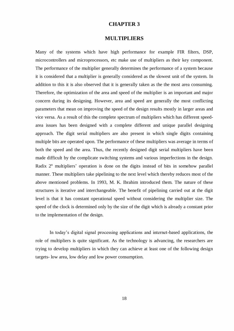
compared at a time. The figure 3.7 shows this comparison using overlapping
technique.
Figure 3.8: 3 Bit Pairing using Overlap Technique
Pairing of the bits starts from the LSB such that the very first block makes use of only
the multiplier’s 2 bits, assuming a 0 for the next bit which is the third bit as shown in
the figure 3.8.
Table 3.1 shows the functional operation of modified booth algorithm. There
are different types of states. The main states are of eight types and while these states
the outcomes can be obtained, which is the multiplication process is followed with the
multiplicand and 0,-1 and -2 consecutively.
Radix-4 Booth algorithm is given below:
1. The sign bit have to be extended by one bit position so as to ensure the even
nature of the number.
2. A 0 must be appended to the multiplier LSB’s right.
3. Each and every partial product will come out to be 0, +Y, –Y, +2Y or –2Y,
depending upon the value of each vector.
2’s complement of Y is taken to obtain negative value of Y and CLA fast adders are
used to perform addition. The multiplicand i.e. Y is then multiplied by shifting Y
towards left by one bit. Therefore, in any case, to design parallel multipliers with n-
bits, partial products of only n/2 need to be generated, where n is the number of the

29
Table 3.1: Recoding Table for Modified Booth Algorithm
Multiplier Bits Block Recorded 1-Bit Pair 2-Bit Booth
i+1 i i-1 i+1 i Multiplier
Value
Partial
Product
0 0 0 0 0 0 Mx0
0 0 1 0 1 1 Mx1
0 1 0 1 -1 1 Mx1
0 1 1 1 0 2 Mx2
1 0 0 -1 0 -2 Mx-2
1 0 1 -1 1 -1 Mx-1
1 1 0 0 -1 -1 Mx-1
1 1 1 0 0 0 Mx0
multiplier bits. The advantage of this described method is that it halves the partial
products’ number. This is an important aspect in circuit designing as it is related to the
circuit’s the propagation delay, and the complexity and power consumed in the
implementation of the design.
The block diagram of the modified booth multiplier is shown in figure 3.9. 16
partial products are obtained with inputs of 32 bits. A 3:2 compressors’ array is used

30
for the addition operation of these partial products. The complete series of sum and
carry results undergoes addition using a ripple carry adder
Figure 3.9: 32×32 Bit Modified Booth Multiplier
3.1.7 Combinational Multiplier
A combinational multiplier is used to multiply two signed or unsigned binary
numbers. In this, the multiplicand (i.e. Y) is multiplied with each single bit of the
multiplier (i.e. X), the product is associated with the bit position in the multiplier, and
to get the final result the obtained product terms are then added. Binary multiplication
has the advantage that it can be achieved easily. If the multiplier bit is 1, then the
result of the multiplication will simply be the shifted form of the multiplicand and if it

31
is 0, then the result will simply be 0. The main drawback of combinational multiplier
is that it takes large area and is slow.
Figure 3.10: Combinational Multiplier Implementation
3.1.8 Wallace Multiplier
Partial product generator is used to obtain partial products by multiplying each single
bit of the multiplier (i.e. X) with the multiplicand (i.e. Y). Both the multiplier and the
multiplicand is of 32-bit, thus generate a total of 32 partial products. A Wallace tree
structure is used to add these partial products of a number of 4:2 compressors which
increases its speed of accumulation. A carry- propagate adder called CLA is used at

32
the final stage which has the sum and carry. The block diagram of 32-bit Wallace tree
multiplier is shown in figure 3.11.
Figure 3.11: 32×32 bit Wallace Tree multiplier’s Block diagram
3.1.9 Sequential Decimal Multiplier
Sequential multiplier is clearly described in its block diagram in figure 3.12. Its
operation will begin with the start pulse and operands will be contained by the data
bus in two consecutive clock pulses. The operands here are A and B. As it receives
data, the multiplication operation is performed and the final result i.e. the product is
again send to the data bus. Sequential realization of the multipliers was done to
overcome the high area cost problem. The biggest limitation with them is their high
latency. Figure 3.12 describes the block diagram of a sequential decimal multiplier.

33
Figure 3.12: Block Diagram of Sequential Multiplier
3.2 STAGES OF MULTIPLICATION
A process of adding a number several times by itself is called multiplication. The
multiplicand (i.e. Y) is added to itself for a specified number of cycles or times which
depends upon the value of multiplier (i.e. X) to form the result. Multiplication operation
consists of these basic three stages:
1. Partial Products Generation
2. Partial Products Accumulation
3. Carry-propagate Addition
Decimal multiplication is considered as the most complex operation. Its complexity level is
mainly higher than the binary multiplication because of the following two reasons: the

34
decimal digits have higher range, which increases the number of multiples of the
multiplicand, thereby decreases the efficiency of decimal values which are represented in
BCD–8421 coding mechanism, because only 9 out of the 16 possible 4–bit combinations can
be represented in BCD-8421 coding technique. Due to these issues and reasons the creation
(i.e. generation) and accumulation (i.e. reduction) of partial products is complicated.
3.2.1 Partial Product Generation
The partial products are generated with the help of easy multiples of X, 2X, 4X, 5X.
In order to avoid the operation with negative numbers, easy multiples are generated
using the flow graph as shown in the figure 3.13. In this figure, the partial product
generation mostly consists of wired shifts and various encoders.
3.2.2 Partial Product Accumulation
Figure 3.13: Generation of easy Multiples
The straight and simply forward approach to implement the PPA is to adopt pairing of
the partial products two at the same time, summing them with the use of an adder and

35
repeat the complete process until just the final result is left. If a single adder is used to
perform all these operations, then this partial product reduction technique will take N-
cycles which mean a grand total of N mechanical delays when the relay adder is used.
3.2.3 Carry Propagate Addition
Figure 3.14: 3:2 Carry Save Adder Generic Scheme
A carry save adder is used to accumulate the partial products resulting in the final sum
and carry. It improves the speed of accumulation of the partial product as it saves the
carry and passes it to the next level of carry select adder. Therefore, the adders in the
same layer become independent of each other and can be executed simultaneously.
Hence the time required for the addition operation is reduced. The carry save adder
tree uses a one’s compliment based radix-2 modified booth algorithm for partial
product generation and accumulation. Accumulation is combined with a carry save
adder tree to compress the partial products.

36
CHAPTER 4
RESEARCH METHODOLOGY AND STRUCTURE
The sequential decimal multiplier proposed in this paper is designed using the algorithm
discussed in the section 4.3. The easy multiples are generated using equations (4.1) to (4.8).
A parallel approach is used to obtain the partial product terms. The complete approach used
in the designing of the proposed sequential decimal multiplier is discussed in this chapter.
4.1 THE PROPOSED SEQUENTIAL DECIMAL MULTIPLIER
Multiplication is the most basic and fundamental operating function in most digital signal
processing algorithms. These algorithms are used for the performance of various operations
and functions like convolution, filtering and many more. According to the static reports it is
clearly shown that approximately 70-75% of the instructions are based on the operations like
addition and multiplication. These are widely used in most of the algorithms which include
microprocessor and DSP algorithms as well. That clearly mentions that most of the execution
time is consumed by these operations. In a system comprising of multiplier, the system
performance usually determined by the performance of the multiplier as it considered as the
slowest unit among all. Hence, optimization of the multiplier’s speed is an important and
major design constraint.
Multiplication process is simply divided into three basic steps, which are generation
of the partial products, reduction of the partial products and the last comes out to be addition
so as to obtain the final result i.e. product. The multiplication operation’s speed can be easily
improved by reducing the number of partial products being generated or by increasing the
accumulating speed of these easily generated partial products.
The main objective of a useful and robust multiplier is to provide a closely and neatly
packed application which has high speed of operation with relatively low power consumption
element. So as to obtain this objective, this reported work deals with the sequential decimal
multiplier.

37
4.2 TOOL AND LANGUAGE USED
The proposed sequential decimal multiplier is designed on the ISE design suite tool and the
language used is VHDL.
Xilinx ISE is a system software tool which was actually produced by Xilinx for
synthesis and analysis of designs in HDL. This tool enables the developer and the user to
synthesize or compile their designs and perform analysis with timing constraints. It also
offers the developer to analyze and review the RTL diagrams and also simulate a reaction of
any design at various stimuli. It also allows the programmer to configure the device being
targeted.
Xilinx ISE is nothing but a design environment designed for the products in FPGA
from Xilinx, and is tightfisted to the defined architecture of such chips, and are not of use
with the FPGA products from other dealers or vendors. The Xilinx ISE is of prime concern in
the circuit synthesis and designing, while simulator used for system-level testing is ISIM or
the ModelSim logic simulator.
VHDL:
VHDL stands for VHSIC Hardware Description Language. The VHSIC stands for Very High
Speed Integrated Circuits. High throughput is a demand for many DSP applications. The
capability to handle/control and evaluate difficult algorithms is a major requirement by many
DSP designers, to hold the required concurrency level.
The VHDL language is used by these modeling needs at all the three levels i.e.
behavioral, implementation and structural. It gives a flexible and adaptable set of description
solutions for modeling the DSP circuits from the system to the gate level. VHDL includes
user-defined types. It also includes user-defined functions, procedures as well as packages.
VHDL is a very powerful, concurrent and high-level programming language from many
aspects. Hence it is used to design the proposed structure.

38
4.3 ALGORITHM AND FLOWCHART OF THE PROPOSED SEQUENTIAL
DECIMAL MULTIPLIER
The complete approach used in this designing of this sequential decimal multiplier is given in
this section. This section includes the algorithm and flowchart of the proposed sequential
decimal multiplier.
4.3.1 Algorithm of the Proposed Sequential Decimal Multiplier
1. The algorithm for the proposed structure is given below.
2. Take two n-digit decimal numbers. Let Xj and Yi be the two 8-digit decimal
numbers, where Xj is the multiplicand and Yi is the multiplier where both i
and j are 0 ≤. i < n and 0 ≤. j < n.
3. Represent each digit of both the multiplicand and the multiplier in BCD-
format i.e. in 8-4-2-1 binary-coded-decimal representation such that each digit
of Xj and Yi is represented as xj3xj
2xj1xj
0 and yi3yi
2yi1yi
0 respectively.
4. Generate easy multiples like 2Xj, 4Xj and 5Xj so as to make the complex
process of multiplication little easier. The following formulas are used for
generation of easy multiples.
:
(4.1)
(4.2)
(4.3)
(4.4)

39
:
:
(4.5)
(4.6)
(4.7)
(4.8)
5. After obtaining the easy multiples, a selector is used to determine (on the basis
of the multiplier digit Yi) the required easy multiples to generate partial
products. The partial products are represented in the double-BCD format i.e.
W[i] = U[i] + V[i], where U[i] and V[i] are BCD numbers.
6. The logical expressions which are used to generate the partial products are
described in the equations (4.9) and (4.10).
(4.9)
(4.10)

40
7. After obtaining the complete range of partial products, they are added to
obtain the final result. As both U and V are generated in a parallel manner,
the latency decreases to a great extend.
4.3.2 Flowchart of the Proposed Sequential Decimal Multiplier
The flowchart for the proposed sequential decimal multiplier is given below. The
flowchart clearly shows the diagrammatical representation of the algorithm used in
the proposed sequential decimal multiplier. It mentions all the necessary steps
involved to generate the result of the multiplication of the multiplier (i.e. X) and the
multiplicand (i.e. Y). The sequence starts from the generation of easy multiples using
the equation (4.1) to equation (4.8) given in the section 4.3.1. Then partial products
are generated in parallel form using the equation (4.9) and equation (4.10). The final
result is obtained from the addition of generated partial products.

41
Fig. 4.1: Flowchart for the Proposed Sequential Decimal Multiplier

42
CHAPTER 5
SIMULATION AND SYNTHESIS RESULTS
A 32*32 bit multiplier has been implemented in VHDL language by using Xilinx ISE tool.
Simulation and synthesis results for this multiplier are derived with the help of Xilinx ISE
tool. The complete details about the hardware used for the proposed multiplier
implementation is given by the synthesis report. The detailed synthesis report is given in
terms of number of LUTs and slices. Number of slices and LUTs are used in FPGA. FPGA
stands for field programmable gate array. The term “field programmable” is used because
FPGA is an integrated circuit which is designed and planned by the user or designer or
customer after manufacturing. The configuration of FPGA is normally described by the
hardware description language (HDL).
In Xilinx FPGAs, there are programmable logic blocks which are known as slices. A
slice is composed of LUTs and flip flops. In the digital logic, a lookup table of an n-bit can be
implemented by making use of a multiplexer in which the select lines of the multiplexer are
used as the input to the LUTs and whose input is maintained a fixed value. Any Boolean
logic function with n-input can be encoded by an n-bit LUT by representing these functions
in the form of truth tables. It results in a very efficient and reliable method to encode Boolean
functions and LUTs. Following are the synthesized and simulated results of the proposed
sequential decimal multiplier-
5.1 32- BIT SEQUENTIAL DECIMAL MULTIPLIER
In this a 32*32 multiplier is implemented. The various simulated and synthesis reports are
mentioned in this section.
5.1.1 Simulation Results
Simulation results are shown in fig.5.1. In this X and Y are taken as inputs with
values as 99999999 and 99999999 respectively.

43
Figure 5.1 (a): Simulation Results
Figure 5.1 (b): Simulation Results
44
The product term obtained by applying the described algorithm in chapter 4 and is
saved in f which is 9999999800000001.
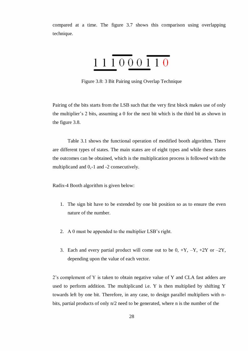
5.1.2 Synthesis Report
Synthesis report is shown in figure 5.2. It can be seen from the figure that the number
of LUTs and flip flops consume 18% and 5% respectively of the total available
numbers, whereas the number of slices occupied from the total available number is
20% and the number of bonded input-output were consumed 198 out of available 232
bonds.
Fig.5.2: Synthesis Report
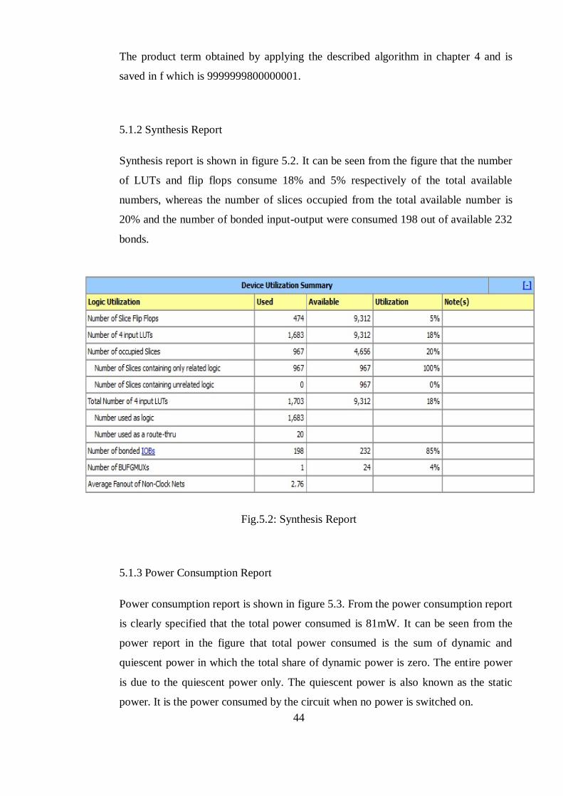
5.1.3 Power Consumption Report
Power consumption report is shown in figure 5.3. From the power consumption report
is clearly specified that the total power consumed is 81mW. It can be seen from the
power report in the figure that total power consumed is the sum of dynamic and
quiescent power in which the total share of dynamic power is zero. The entire power
is due to the quiescent power only. The quiescent power is also known as the static
power. It is the power consumed by the circuit when no power is switched on.
45
Figure 5.3: Power Consumption Report
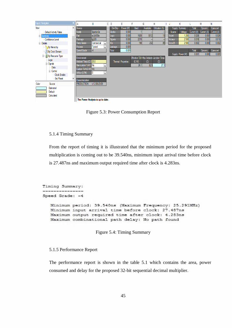
5.1.4 Timing Summary
From the report of timing it is illustrated that the minimum period for the proposed
multiplication is coming out to be 39.540ns, minimum input arrival time before clock
is 27.487ns and maximum output required time after clock is 4.283ns.
Figure 5.4: Timing Summary
5.1.5 Performance Report
The performance report is shown in the table 5.1 which contains the area, power
consumed and delay for the proposed 32-bit sequential decimal multiplier.

46
Table 5.1: Performance Report Table
Number of slices 967
Number of LUTs 1703
Power Consumed (in mW) 81
Delay (in ns) 39.54

47
CHAPTER 6
CONCLUSION AND FUTURE SCOPE
6.1 CONCLUDING REMARKS
The proposed sequential decimal multiplier is implemented in VHDL using Xilinx ISE tool.
The performance report table clearly shows the net area, delay and power consumed by the
multiplier. This multiplier consumes least possible power. The proposed multiplier is
applicable for unsigned decimal numbers only. This multiplier uses 8-4-2-1 BCCD coding
technique. The delay incurred in the proposed work is 39.54 ns with a power consumption of
81 mW. The total power is due to the quiescent power and its dynamic share is zero.
6.2 FUTURE SCOPE
As mentioned in the conclusion that the proposed decimal multiplier is applicable for only
unsigned numbers, it brings the chance to design a multiplier in future that can be applicable
for signed numbers as well. In this section coding technique used is 8-4-2-1 BCD. Besides
this work, it is still possible to make use of some other coding techniques such as decimal 4-
2-2-1 coding mechanism.

48
REFERENCES
[1] Richards R. K., “Arithmetic Operations in Digital Computers,” Van Nostrand, NewYork,
1955.
[2] Dadda L., “Some schemes for parallel multipliers”, Alta Frequenza, Vol. 19, pp. 349–356,
Mar, 1965.
[3] Schmookler M. S. and Weinberger A. W., “High Speed Decimal Addition”, IEEE Trans.
Computers, Vol. C-20, pp. 862-867, 1971.
[4] Larson R. H., “High Speed Multiply Using Four Input Carry Save Adder”, IBM Technical
Disclosure Bulletin, 1973.
[5] Bhasker Jayaram, “A VHDL Primer”, PTR Prentice Hall Englewood Cliffs, New Jersey,
1992.
[6] Roth Charles H., Jr, “Digital System Design Using VHDL”, The University Of Texas at
Austin, 1998.
[7] Al-Khalili D., “Comparison of 32-bit multipliers for various performance measures”, ICM
2000 Proceedings of the 12th International Conference on Microelectronics (IEEE Cat No
00EX453) ICM-00, 2000.
[8] Erle M.A., and Schulte M.J., “Decimal multiplication via carry-save addition”.,Proc. IEEE
Int. Conf. Application-Specific Systems, Architectures, and Processors, The Netherlands, pp.
348–358, June 2003.
[9] Kenney R. D., Schulte M. J., and Erle M. A., “A high-frequency decimal multiplier,” IEEE
International Conference on computer Design: VLSI in Computers and Processors (ICCD),
pp. 26-29, October 2004.
[10] Erle, M.A., Schwartz E.M., and Schulte M.J., “Decimal Multiplication with Efficient Partial
Product Generation”, 17th IEEE Symposium on Computer Arithmetic, pp. 21-28, June 2005.

49
[11] Vazquez A., and Antelo E., “Conditional speculative decimal addition”, Proc. 7th Conf. Real
Numbers and Computers (RNC7), France, pp. 47–57, July 2006.
[12] Lang T. and Nannarelli A., “A Radix-10 Combinational Multiplier”, Proceedings of 40th
Asilomar Conference on Signals, Systems and Computers, 2006.
[13] Schulte M. J. and Hickmann B. J., “Decimal Floating-Point Multiplication via Carry-Save
Addition”, 18th IEEE Symposium on Computer Arithmetic (ARITH 07), 06/2007.
[14] Montuschi P., Vazquez A., Antelo E., “A New Family of High Performance Parallel Decimal
Multipliers”, 18th IEEE Symposium on Computer Arithmetic (ARITH 07), 06/2007.
[15] Jaberipur G., and Kaivani A., “Improving the Speed of Parallel Decimal Multiplication”,
IEEE Transactions on Computers, 2009.
[16] Tsen C., Compton K., Hickmann B.J., Schulte M.J., Gonzalez-Navarro S., “A Combined
Decimal and Binary Floating-Point Multiplier”, 20th IEEE International Conference, 2009.
[17] Vazquez A., Antelo E., and Montuschi P., “Improved Design of High- Performance Parallel
Decimal Multipliers”, IEEE Transactions on Computers, pp. 679–693 2010.
[18] Deshpande A., “Squaring units and a comparison with multipliers”, 2010 53rd IEEE
International Midwest Symposium on Circuits and Systems, 08/2010.
[19] Seo Young-Ho, and Kim Dong-Wook, “A New VLSI Architecture of Parallel Multiplier–
Accumulator Based on Radix-2 Modified Booth Algorithm”, IEEE Transactions on Very
Large Scale Integration (VLSI) Systems, 2010.
[20] Kaivani A., Hosseiny A. and Jaberipur G., “Improving the Speed of Decimal Division,” IET
Computer and Digital Techniques, Vol. 5, 2011.
[21] Aparna P.R. and Thomas N., “Design and implementation of a high performance multiplier
using HDL”, 2012 International Conference on Computing Communication and Applications,
02/2012.

50
[22] Bozdas K., Alkar A.Z., “Analysis on the column sum boundaries of decimal array
multipliers”, Circuits and Systems (MWSCAS), IEEE 55th International Midwest
Symposium, 2012.
[23] Kaivani A., Chen Li, and Ko Seok-Bum, “High-frequency sequential decimal multipliers”,
IEEE International Symposium on Circuits and Systems, 2012.
[24] Juang Tso-Bing, Kuo Han-Lung, Peng Hsin-Hao, “Parallel and digit-serial implementations
of area-efficient 3-Operand Decimal Adders”, SoC Design Conference (ISOCC)
International, 2012.
[25] Rajput S., Shukla R., Praveen P., and Anand A., “Implementation of High Speed and Low
Power Hybrid Adder Based Novel Radix 4 Booth Multiplier”, 2013 International Conference
on Communication Systems and Network Technologies, 2013.
[26] Gandhi D.R., and Shah N.N., “Comparative analysis for hardware circuit architecture of
Wallace tree multiplier”, 2013 International Conference on Intelligent Systems and Signal
Processing (ISSP), 2013.
[27] Sinha A., Sarkar M., Acharyya S., and Chakraborty S., “A novel reconfigurable architecture
of a DSP processor for efficient mapping of DSP functions using field programmable DSP
arrays”, ACM SIGARCH Computer Architecture News, 2013.
[28] Rahman S.A., and Khanna G., “Performance metrics analysis of 4-bit array multiplier circuit
using 2 PASCL logic”, 2014 International Conference on Green Computing Communication
and Electrical Engineering (ICGCCEE), 2014.
[29] Ko Seok-Bum, Han Liu, and Kaivani A., "Improved design of high-frequency sequential
decimal multipliers", Electronics Letters, 2014.
[30] Singh K.N. and Huirem T.K., “A review on various multipliers designs in VLSI”, 2015
Annual IEEE India Conference (INDICON), 2015

51
[31] Kam Hei, and Chen Fred, “Micro-relay Circuits for VLSI Applications”, Microsystems and
Nanosystems, Vol.1, 2015.

Sonal_05-09-2017by Sonal Gupta
Submission date: 05-Sep-2017 02:34PM (UTC+0530)Submission ID: 843056771File name: Sonal_Gupta_601562024.doc (1.23M)Word count: 9427Character count: 49556

9%SIMILARITY INDEX
5%INTERNET SOURCES
3%PUBLICATIONS
4%STUDENT PAPERS
1 2%
2 1%
3 1%
4 1%
5 <1%
6 <1%
Sonal_05-09-2017ORIGINALITY REPORT
PRIMARY SOURCES
ijareeie.comInternet Source
Submitted to ABV-Indian Institute ofInformation Technology and ManagementGwaliorStudent Paper
Submitted to Thapar University, PatialaStudent Paper
Kaivani, Amir, Li Chen, and Seokbum Ko."High-frequency sequential decimalmultipliers", 2012 IEEE InternationalSymposium on Circuits and Systems, 2012.Publicat ion
M.J. Schulte. "Decimal Multiplication withEfficient Partial Product Generation", 17thIEEE Symposium on Computer Arithmetic(ARITH 05), 2005Publicat ion
ethesis.nitrkl.ac.inInternet Source
7 <1%
8 <1%
9 <1%
10 <1%
11 <1%
12 <1%
13 <1%
14 <1%
15
www.ijettjournal.orgInternet Source
Submitted to Rivier UniversityStudent Paper
www.coursehero.comInternet Source
Submitted to The University of the SouthPacif icStudent Paper
ijartet.comInternet Source
Submitted to K L UniversityStudent Paper
D. Al-Khalili. "Comparison of 32-bit multipliersfor various performance measures", ICM 2000Proceedings of the 12th InternationalConference on Microelectronics (IEEE Cat No00EX453) ICM-00, 2000Publicat ion
Jaberipur, Ghassem, and Amir Kaivani."Improving the Speed of Parallel DecimalMultiplication", IEEE Transactions onComputers, 2009.Publicat ion
ecommons.usask.ca

<1%
16 <1%
17 <1%
18 <1%
19 <1%
20 <1%
21 <1%
22 <1%
Internet Source
Aditya Deshpande. "Squaring units and acomparison with multipliers", 2010 53rd IEEEInternational Midwest Symposium on Circuitsand Systems, 08/2010Publicat ion
www.ijetae.comInternet Source
www.ece.virginia.eduInternet Source
Submitted to Malaviya National Institute ofTechnologyStudent Paper
Ko, Seok-Bum, Liu Han, and A. Kaivani."Improved design of high-frequency sequentialdecimal multipliers", Electronics Letters, 2014.Publicat ion
Seo, Young-Ho, and Dong-Wook Kim. "A NewVLSI Architecture of Parallel Multiplier–Accumulator Based on Radix-2 Modif ied BoothAlgorithm", IEEE Transactions on Very LargeScale Integration (VLSI) Systems, 2010.Publicat ion
Sridhar, Laavanya, and V. Lakshmi Prabha."RFID based access control protection scheme

23 <1%
24 <1%
25 <1%
26 <1%
27 <1%
28 <1%
for SRAM FPGA IP cores", Microprocessors andMicrosystems, 2013.Publicat ion
Moore, Ciara, Neil Hanley, John McAllister,Máire O’Neill, Elizabeth O’Sullivan, and XiaolinCao. "Targeting FPGA DSP Slices for a LargeInteger Multiplier for Integer Based FHE",Lecture Notes in Computer Science, 2013.Publicat ion
www.i-scholar.inInternet Source
documents.mxInternet Source
Submitted to Dr. Pillai Global AcademyStudent Paper
Submitted to National Institute of Technology,RourkelaStudent Paper
Teymourzadeh, . "On-Chip Implementation ofHigh Resolution High Speed Floating PointAdder/Subtractor with Reducing Mean Latencyfor OFDM", American Journal of Engineeringand Applied Sciences, 2010.Publicat ion

Exclude quotes On
Exclude bibliography On
Exclude matches < 10 words