IMPLEMENTATION OF SELF EXCITED INDUCTION GENERATOR … · synchronous generator (alternator), is...
6
IJRET: International Journal of Research in Engineering and Technology eISSN: 2319-1163 | pISSN: 2321-7308 __________________________________________________________________________________________ Volume: 02 Issue: 08 | Aug-2013, Available @ http://www.ijret.org 188 IMPLEMENTATION OF SELF EXCITED INDUCTION GENERATOR (SEIG) WITH IGBT BASED ELECTRONIC LOAD CONTROLLER (ELC) IN WIND ENERGY SYSTEMS Amit Kumar 1 , V. K. Sharma 2 1 & 2 Department of Electrical & Electronics Engineering, Bhagwant Institute of Technology, Muzaffarnagar, U.P. India, [email protected] Abstract In this paper, a mathematical model of the Self-Excited Induction Generator (SEIG) is developed to analyze the operation of it in wind energy systems. In such type of wind scheme often whole generating system is isolated from the grid and supply electricity to the remote communities. A wind energy system usually a low/medium speed projects driven by controlled/uncontrolled micro wind turbines. The single point operation of these generators is realized; in such a manner that speeds, voltage, currents of generators remain constant under various operating loads conditions. The Electronic Load Controller (ELC) is modeled here for the controlled operation of WES against various load condition. Here the proposed electrical system are modeled and simulated in MATLAB using Simulink and Sim Power System (SPS) set toolboxes and different aspects of the proposed system are studied. On the basis this model different characteristics of SEIG with ELC are analyzed which shows its suitability in wind energy systems. Index Terms: SEIG, ELC, Wind Energy, and Induction generator etc ---------------------------------------------------------------------***------------------------------------------------------------------------- 1. INTRODUCTION Small scale power generation near consumer’s premises has received greater attention in recent years for use in remote and rural communities due to the cost and complexity involved in the grid extension. Thus, suitable stand-alone systems using locally available energy sources have become a preferred option. Alternatively, wind energy system projects may be built in isolated areas that would be uneconomic to serve from a network, or in areas where there is no national electrical distribution network. Since wind energy system projects usually have minimal reservoirs and civil construction work, they are seen as having a relatively low environmental impact compared to large hydro [1]. The development of low/medium speed and innovative synchronous generators specially with Induction Generators (IG) have received attention from numerous individuals around the world. IGs offer several advantages to hydro and wind power plants compare to other generators available in the market. Its construction, self-start quality, low maintenance and low cost draw greater attention from the last decades of WESs developers. 2. SELF-EXCITED INDUCTION GENERATOR Induction machine (IM) is quite popular with isolated micro- hydro power plants. It is a singly-excited ac machine. Stator winding of a 3-phase IM is connected to a 3-phase ac source and rotor winding receives its energy from stator by means of electro-magnetic induction. Based on the slip value, an IM works in motor and generator mode as [1, 2, 3, 4, 5, and 6]: i. In motoring mode (0 < slip < 1), rotor rotates in the direction of rotating field produced by the stator currents. The slip varies from ‘1’ at stand still to ‘0’ at synchronous speed. ii. In generating mode (-1 < slip < 0), stator terminals are connected to a constant frequency voltage source and rotor is driven at above synchronous speed by a prime mover. SEIG employs cage rotor construction with shunt capacitors connected at its terminals for excitation. The shunt capacitors may be either constant or variable. The IG has very similar construction as induction motor with some possible improvements in efficiency. As the speed during induction generator operation is not synchronous, it is also called an asynchronous generator. There are numerous advantages of a permanent magnet synchronous generator which are enlisted below [1, 3, 4, 6 & 7-10] i. Brushless and rugged construction ii. Low cost iii. Maintenance and operational simplicity iv. Self-protection against faults v. Good dynamic response vi. Capability to generate power at varying speed
Transcript of IMPLEMENTATION OF SELF EXCITED INDUCTION GENERATOR … · synchronous generator (alternator), is...

IJRET: International Journal of Research in Engineering and Technology eISSN: 2319-1163 | pISSN: 2321-7308
__________________________________________________________________________________________
Volume: 02 Issue: 08 | Aug-2013, Available @ http://www.ijret.org 188
IMPLEMENTATION OF SELF EXCITED INDUCTION GENERATOR
(SEIG) WITH IGBT BASED ELECTRONIC LOAD CONTROLLER (ELC)
IN WIND ENERGY SYSTEMS
Amit Kumar 1, V. K. Sharma2 1 & 2 Department of Electrical & Electronics Engineering, Bhagwant Institute of Technology,
Muzaffarnagar, U.P. India, [email protected]
Abstract In this paper, a mathematical model of the Self-Excited Induction Generator (SEIG) is developed to analyze the operation of it in wind energy systems. In such type of wind scheme often whole generating system is isolated from the grid and supply electricity to the remote communities. A wind energy system usually a low/medium speed projects driven by controlled/uncontrolled micro wind turbines. The single point operation of these generators is realized; in such a manner that speeds, voltage, currents of generators remain constant under various operating loads conditions. The Electronic Load Controller (ELC) is modeled here for the controlled operation of WES against various load condition. Here the proposed electrical system are modeled and simulated in MATLAB using Simulink and Sim Power System (SPS) set toolboxes and different aspects of the proposed system are studied. On the basis this model different characteristics of SEIG with ELC are analyzed which shows its suitability in wind energy systems. Index Terms: SEIG, ELC, Wind Energy, and Induction generator etc
---------------------------------------------------------------------***-------------------------------------------------------------------------
1. INTRODUCTION
Small scale power generation near consumer’s premises has received greater attention in recent years for use in remote and rural communities due to the cost and complexity involved in the grid extension. Thus, suitable stand-alone systems using locally available energy sources have become a preferred option. Alternatively, wind energy system projects may be built in isolated areas that would be uneconomic to serve from a network, or in areas where there is no national electrical distribution network. Since wind energy system projects usually have minimal reservoirs and civil construction work, they are seen as having a relatively low environmental impact compared to large hydro [1]. The development of low/medium speed and innovative synchronous generators specially with Induction Generators (IG) have received attention from numerous individuals around the world. IGs offer several advantages to hydro and wind power plants compare to other generators available in the market. Its construction, self-start quality, low maintenance and low cost draw greater attention from the last decades of WESs developers. 2. SELF-EXCITED INDUCTION GENERATOR
Induction machine (IM) is quite popular with isolated micro-hydro power plants. It is a singly-excited ac machine. Stator winding of a 3-phase IM is connected to a 3-phase ac source
and rotor winding receives its energy from stator by means of electro-magnetic induction. Based on the slip value, an IM works in motor and generator mode as [1, 2, 3, 4, 5, and 6]:
i. In motoring mode (0 < slip < 1), rotor rotates in the direction of rotating field produced by the stator currents. The slip varies from ‘1’ at stand still to ‘0’ at synchronous speed.
ii. In generating mode (-1 < slip < 0), stator terminals are connected to a constant frequency voltage source and rotor is driven at above synchronous speed by a prime mover.
SEIG employs cage rotor construction with shunt capacitors connected at its terminals for excitation. The shunt capacitors may be either constant or variable. The IG has very similar construction as induction motor with some possible improvements in efficiency. As the speed during induction generator operation is not synchronous, it is also called an asynchronous generator. There are numerous advantages of a permanent magnet synchronous generator which are enlisted below [1, 3, 4, 6 & 7-10]
i. Brushless and rugged construction ii. Low cost
iii. Maintenance and operational simplicity iv. Self-protection against faults v. Good dynamic response
vi. Capability to generate power at varying speed

IJRET: International Journal of Research in Engineering and Technology eISSN: 2319-1163 | pISSN: 2321-7308
__________________________________________________________________________________________
Volume: 02 Issue: 08 | Aug-2013, Available @ http://www.ijret.org 189
3. SEIG WITH OTHER GENERATORS
Generators
Based on the requirement conventionally in WESs synchronous generator (alternator), is commonly used and in future the researchers focusing on Permanent Magnet Synchronous Generator (PMSG), Doubly Fed Induction Generator (DFIG). These generators used to convert the mechanical energy of flowing water into the electrical energy.
As compared to the synchronous generator in a SEIG; brushless and rugged construction and capability to generate power at varying speed and which mean substantial increase in the efficiency. Table 1 shows the comparison of SEIG with other generators used in WESs on the basis various parameters [2-11]. Table 1 clearly describe SEIG that it could be the better option for low/medium speed applications in future and specially in WESs by considering all the parameters.
Table 1: Comparison of SEIG with different generators used in WESs
4. MATHEMATICAL MODELING OF SEIG
The considered SEIG-ELC system consists of an induction generator capacitor bank, consumer loads (static as well as dynamic loads) and ELC with control circuit and is shown in Figure 1. The dynamic models of symmetrical three-phase induction machine are derived considering the following assumptions [10]:
i. The change in resistance due to the change in frequency and temperature is neglected.
ii. The MMF space and time harmonics are neglected. iii. The core loss is neglected.
The dynamic model of the three-phase squirrel-cage induction generator is developed by using a stationary d-q axes reference frame [5, 6, 8, 10 & 11] and the relevant equations are for mechanical and electrical systems given below.
S.No. Parameters SEIG Wound Rotor Induction Generator
Synchronous Generator with coiled field
PMSG
1. Construction Simple and Robust
Complex Structure Complex Structure Simple and Robust
2. Operation with Slip ring
Reliable Slipping rings for DFIG Slipping Rings Reliable
3. Large Scale Inverter Appl.
Small capacitor bank
Inverters for 25% to 50% of nominal power
Large Scale Inverter Large Scale Inverter
4. Inverter Control Requirement
Simple inverter Control
Complex inverter Control Simple inverter Control
Simple inverter control
5. No. of Controlling Inverter required
One controlling inverter
Two controlling inverter
One controlling inverter
One controlling inverter
6. No. of Rectifier+ Inverter
1 Rectifier+ 1inverter
-- 1field controller + 1inverter
1 Rectifier + 1 inverter
7. Slip ring Requirement
-- No Slipping Rings for BDFG
Regular Maintenance
No Slipping Rings
8. Maintenance Low Maintenance High Maintenance High Maintenance Low Maintenance 9. Torque Behaviour Flat Torque Wavy Torque Wide range Torque Flat Torque 10. Cost Low Cost High Cost High Cost Low Cost* 11. Weight Small Large Large Small and Light
weight 12. Efficiency Medium
efficiency High efficiency with DFIG High efficiency in a
wide range of load Better Efficiency At low speed
13. Power Coefficient Low power coefficient
Low power coefficient
Low power coefficient
High power coefficient
Capacitor Needs Needs Capacitors Needs Capacitors Ease of Voltage Control
No need of Capacitors

IJRET: International Journal of Research in Engineering and Technology eISSN: 2319-1163 | pISSN: 2321-7308
__________________________________________________________________________________________
Volume: 02 Issue: 08 | Aug-2013, Available @ http://www.ijret.org 190
Te = (3P/4) Lm (iqs idr – ids iqr) (1)
Fig.-1: Schematic diagram of three-phase SEIG with ELC and
Load Tshaft = Te + J (2/P) pwg (2) (2) The d and q axes voltages in the stationary reference frame are as follows:
vds = (2/3) (va – (vb/2) – (vc/2) (3)
vqs = (2/3) (√3vb/2) – (√3vc/2) (4) The derivative of the rotor speed from (4) is
p.wg= (P/2). (Tshaft-Te)/J (5) Where, (all quantities in the rotor reference frame):
Te = developed electromagnetic torque of the SEIG Tshaft = electromechanical torque of the SEIG P = the number of poles Lm = the magnetizing inductance iqs = q-axis component of stator current idr = d-axis component of rotor current ids = d-axis component of stator current iqr = q-axis component of rotor current J = moment of inertia wg = rotor speed of SEIG p = [d/dt] vds = direct axis component of stator voltage vqs = quadrature axis component of stator voltage va vb vb = voltages at induction generator terminals
4.1 Modelling of ELC The aim of an ELC is to reduce the cost of a wind energy system installation by replacing the mechanical governor with an electronic circuit. The basic principle of an ELC is that the electrical load on the generator must be constant even though the consumer load may vary in an unpredictable manner from zero to full rated load of the system. In the event of change of consumer load, a ballast load is adjusted so that the totals load on the generator remains constant as [10]:
Pout = Pc + Pd (6) Where, Pout is the generated power of the generator (which should be constant), Pc is the consumer power and Pd is the dump load power. This dump power (Pd) may be used for space heating, water heating, battery charging, cooking, baking etc. Figure 2 shows the diagram of ELC with control circuit [9-11]. 4.2 Simulink /MATLAB Model of SEIG
A simulation model is developed in MATLAB using Simulink and SPS block set. The simulation is carried out on MATLAB version 10 with ode23t solver. The electrical system is simulated with different loads and modeled using resistive and inductive elements. The unbalanced load is modeled using breakers in individual phases as depicted in Figure 3. The parameters of the various components of the system are given in APPENDIX-A.
Fig.-2: Schematic diagram of ELC with Control circuit
vmax = 2Rf id + 2Lf pid +vd (7)
pvd = (id – iL) / C (8)
iL = (vd/ RdL1) + S (vd/RdL2) (9)
IJRET: International Journal of Research in Engineering and Technology eISSN: 2319-1163 | pISSN: 2321-7308
__________________________________________________________________________________________
Volume: 02 Issue: 08 | Aug-2013, Available @ http://www.ijret.org 191
vab (V)2
-K-
rpm3
1
rpm2
3.5
rpm1
-K-
rpm
pulse
Discrete,Ts = 5e-005 s.
powerguiir,is (A)
Fo=75Hz
f4
Fo=75Hz
f3
f2
Fo=75Hz
f1
Fo=75Hz
f
v+-
Vga3
Vga, Iga1
A
B
C
+
-
Universal Bridge
A
B
C
a
b
c
Three-Phase Breaker2
A
B
C
a
b
c
Three-Phase Breaker1
Vabc
IabcA
B
C
a
b
c
Three-PhaseV-I Measurement
A
B
C
Three-PhaseSeries RLC Load
In1
In2
In3
Out1
SubsystemlightBlue
Saturation
m
A
B
C
Tm
SEIG
N (rpm)1
N (rpm)
g
12
Ideal Switch
i+-
Ica2i+ -
Ica1
i+-
Ica
IDa
[A]
Goto
[A]
From
Ve PWM
Electronic load controller
Uref Pulses
DiscretePWM Generator
i+ -
Current Measurement2
i+ -
Current Measurement1
484
Constant1
1000
Constant
Conn1Conn2Conn3
Capacitor bank
<Rotor current ir_a (A)>
<Stator current is_a (A)>
<Rotor speed (wm)>
<Electromagnetic torque Te (N*m)>
Where Lf source inductance, Rf source resistance and C filtering capacitor and S is the switching function indicating the switching status of the IGBT switch [APPENDIX-B].
Fig.-3: Simulink/MATLAB Model of SEIG
5 SIMULATION RESULTS AND DISCUSSION
The performance of the SEIG is studied with various operating condition like in wind energy power plants. The performance of PMSG is analyzed with the Resistive Load and RLC Load. The simulated waveforms of SEIG electromagnetic torque (Te), rotor speed (ωr), 3-Ф Stator Voltage (Vabc), and 3-Ф current (Iabc) are shown in Figures 4-9 for different operating conditions. Following cases are taken for study: 5.1 Self-excitation and Voltage Build up
In this case, SEIG is started at no load with excitation capacitors of 200 µF per phase. Figures 4-5 show voltage build up for all three lines at SEIG terminals, capacitor currents, Electromagnetic torque and rotor speed respectively.
Fig.-4: Three line voltages & currents build up at SEIG terminals
Fig.-5: Torque and rotor speed and Frequency of generated
voltage of SEIG 5.2 Resistive Loading of SEIG
Initially SEIG is running under no load, at t=1 sec, resistive load of 1.5 kW (Appendix-B) is switched on. Load draws a heavy current at starting but after 1.2 sec., it settles to a steady state value. After that at t=1.2 sec. SEIG again switches to no load as shown in Figures 6-7. 5.3 Three Phase Fault at SEIG
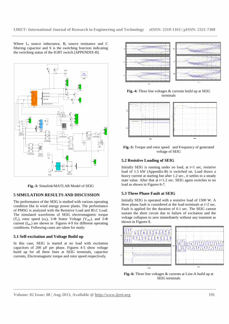
Initially SEIG is operated with a resistive load of 1500 W. A three phase fault is considered at the load terminals at t=2 sec. Fault is applied for the duration of 0.1 sec. The SEIG cannot sustain the short circuit due to failure of excitation and the voltage collapses to zero immediately without any transient as shown in Figures 8.
Fig.-6: Three line voltages & currents at Line-A build up at
SEIG terminals

IJRET: International Journal of Research in Engineering and Technology eISSN: 2319-1163 | pISSN: 2321-7308
__________________________________________________________________________________________
Volume: 02 Issue: 08 | Aug-2013, Available @ http://www.ijret.org 192
Fig.-7: Torque and rotor speed of SEIG
Fig.-8: Three line voltages, currents and Torque speed of
SEIG terminals
5.4 Line-Line Fault at SEIG
A line to line short circuit is applied between two lines A and B at the load terminals for the duration of 0.1 sec from t = 2 sec. to t = 2.1 sec. The SEIG cannot sustain the short circuit and the voltage collapses to zero immediately without any transient as shown in the Figures 9. CONCLUSIONS
This paper presented the performance analysis of a SEIG supplying static constant torque. Steady state and transient operations of the SEIG are studied under these loads. The study has provided more detailed information on the performance of the SEIG, such as steady-state and transient waveforms, variation of basic parameters such voltage, current, speed and torque with loads.
Fig.-9: Three line voltages, currents, torque and speed at SEIG
terminals
The dynamic behaviour of the SEIG has been demonstrated and it reveals that SEIG can be used satisfactorily in micro-hydro with uncontrolled turbine. It reveals from the study that system is more efficient and reliable with Electronic Load Controller. This study has practical significance due availability of enormous wind energy system potential in remote locations in several countries. Due to lower initial costs, replacement of synchronous and other generators seems quite logical. REFERENCES
[1] MNRE official website: http://mnre.gov.in (also exist http://mnes.nic.in), Feb. 2012.
[2] http://en.wikipedia.org/wiki/Induction_generator, accessed on Feb. 2012.
[3] R. C. Bansal, “Three-Phase Self-Excited Induction Generators: An Overview”, IEEE Transactions on Energy Conversion, Vol. 20, No. 2, pp.292-299, Jun. 2005.
[4] G.K. Singh, “Self-Excited Induction Generator Research-a survey”, Electric Power Systems Research, Vol. 69, No. 1, pp. 107-114, Aug. 2003.
[5] G. K. Singh, “Modeling and Experimental Analysis of a Self-excited Six-phase Induction Generator for Stand-alone Renewable Energy Generation”, Renewable Energy, Vol. 33, No. 7, pp. 1605-1621, Jul. 2008.
[6] S. N. Mahato, M. P. Sharma, and S. P. Singh, “Transient Analysis of a Single-Phase self-regulated self-Excited Induction Generator using a Three-Phase Machine”, Electric Power Systems Research, Vol. 77, No. 7, pp. 839-850, May 2007.
[7] S. K. Jain, J. D. Sharma and S. P. Singh, “Transient Performance of Three-phase Self-Excited Induction Generator During Balanced and Unbalanced Faults”, IEE Proc. Inst. Elect. Eng., Gener., Transm. Distrib., Vol. 149, No. 1, pp. 50-57, Jan. 2002.
[8] Bhim Singh, S. S. Murthy and Sushma Gupta, “Analysis and Design of Electronic Load Controller for Self-Excited Induction Generators”, IEEE Transactions on Energy Conversion, Vol. 21, No. 1, pp. 285-293, March 2006
[9] B. Singh, S. S. Murthy, Madhusudan, M. Goel, and A. K. Tandon, “A Steady State Analysis on Voltage and Frequency Control of Self-Excited Induction Generator in Micro-Hydro System”, IEEE Transactions on Industrial Applications, Vol. 1, No. 1, pp. 1-6, Dec. 2006.
[10] Bhim Singh, S. S. Murthy and Sushma Gupta, “Transient Analysis of Self-Excited Induction Generator with Electronic Load Controller (ELC) Supplying Static and Dynamic Loads”, IEEE Transactions on Industrial Applications, Vol. 41, No. 5, pp. 1194-1204, Sep. 2005.
[11] B. Singh, S.S. Murthy and S. Gupta,“Analysis and Implementation of an Electronic Load Controller for a Self-Excited Induction Generator”, IEE Proc.-Gener. Transm. Distrib., Vol. 151, No. 1, pp. 51-60, Jan. 2004.

IJRET: International Journal of Research in Engineering and Technology eISSN: 2319-1163 | pISSN: 2321-7308
__________________________________________________________________________________________
Volume: 02 Issue: 08 | Aug-2013, Available @ http://www.ijret.org 193
APPENDICES
A. Parameters of SEIG: 3.73 kW, 415 V, 50 Hz, Y-connected, 24 pole, RS = 0.6837 Ω, Rr=0.45, Lis= 0.004152H, Lir= 0.008152H, Lm=0.011846 H, Inertia (J) = 0.1 kg-m2, Friction Fcator= 0.008141, F (N.m.s) B. ELC Rating: Power Rating=3.7kW (selected), Voltage Rating of rectifier and chopper switch = 900 V, Current Rating of rectifier and chopper switch = 15 A, Rating of Dump load = 15 Ω, Rating of DC filtering capacitor = 380 µF C. Resistive Load: 1.5kW BIOGRAPHIES
Amit Kumar received B.Tech degree in Electronics & Instrumentation Engineering from Bhagwant Institute of Technology in 2010. He is currently pursuing Masters of Technology in Power Electronics from Bhagwant Institute of Technology,
Muzaffarnagar, India. His area of interest is Induction Generator, Power Electronics.
V. K. Sharma (1961) received his bachelor degree from KREC Surathkal in 1984, M. Tech. in Power Electronics from IIT Delhi in 1993, and PhD from IIT Delhi in 2000. He is recipient of various scholarships, Railway Board Medal and has completed a few AICTE sponsored projects. He has worked with College of Engineering, at
Pravaranagar, and Jamia Millia Islamia University in New Delhi. Currently, he is a full Professor in the Department of Electronics & Telecommunication Engineering at Maharashtra Academy of Engineering, Alandi, under Pune University, India. He has visited USA, Germany Malayasia, and Hong Kong to present his research findings in IEEE conferences. He has worked as post doc fellow during 2001-2002 at Ecole de technologies superieure, Montreal, Canada. He is a regular reviewer for several IEEE conferences and national/international journals. He is a member of Institution of Engineers (India) and Fellow of IETE, India. His research interests include power electronics, and application of computer communication in hybrid electric vehicle