Implementation of Multicast Routing on IPv4 and IPv6 Networks · In jperf terminology, the client...
13
International Journal on Recent and Innovation Trends in Computing and Communication ISSN: 2321-8169 Volume: 5 Issue: 6 1455 – 1467 _______________________________________________________________________________________________ 1455 IJRITCC | June 2017, Available @ http://www.ijritcc.org _______________________________________________________________________________________ Implementation of Multicast Routing on IPv4 and IPv6 Networks Dr.Sridevi, Assistant Professor, Dept of Computer Science, Karnatak University, Dharwad. Abstract: Fast developing world of technology, multimedia applications are quickly growing their performance into the Internet and shared networks. Multicast routing protocols sprint over unicast routing protocols to endow with well-organized routing of such applications. This research paper intended to considerate how the transition from Internet Protocol version 4 to Internet Protocol version 6 would influence multicast routing. The multicast routing protocol was used over both Internet Protocol version 4 and Internet Protocol version 6 and a mixed Internet Protocol version 4 - Internet Protocol version 6. Netwok parameters such as overhead, throughput and jitter network are evaluated. Keywords: Multicast, unicast, anycast, IPv4, IPv6, jperf __________________________________________________*****_________________________________________________ 1. Introduction The Internet has grown tremendously over the last few years. Large numbers of users subscribe to online multimedia services such as video streaming. Messenger services such as Skype and Gtalk are replacing traditional phones for long distance calls across urban areas in many countries. Information exchange can broadly be classified as unicast (one-to-one), broadcast (one-to-all) and multicast (one-to-many). A typical example of multicasting is Yahoo Messenger where multiple hosts subscribe to the service and the server communicates only with those hosts that have subscribed to it. One of the biggest advantages of multicasting is the conservation of bandwidth. The multicast server sends out only one packet and the router then generates multiple packets to reach each of the receivers. In this manner the network resources are used efficiently. Also, multicasting ensures timely reception of the data by the receivers [1]. In unicast routing, the server sends out a packet to each of the receivers. A more recent variation of multicast is anycast. It is a one-to-“one-of-many” distribution. There may be multiple recipients of an anycast message, but the sender sends the message only to the node that is logically or topologically the closest to it. The figure below is a comparison of unicast, broadcast, multicast and anycast. The survey was aimed at gathering which multicast routing protocols were used widely. The results of the survey indicated enterprises used multicast applications. Protocol Independent Multicast (PIM) was the multicast routing protocol preferred by most enterprise network administrators, since it is independent of the underlying unicast routing protocol in the network. Unlike Distance Vector Multicast Routing Protocol (DVMRP) that can be used only in networks that use a distance-vector unicast routing protocol, PIM can be used whether the unicast routing protocol is a distance-vector or link-state protocol. For this reason, PIM was chosen for this study. This research paper is a quantitative one involving gathering results from laboratory experiments. The laboratory experimental setup consisted of four Cisco 2811 routers connected back to back using Cisco serial WAN Interface Cards (WICs). The first and the last routers in the chain were connected to hubs. Each hub had two PCs connected to it. One of the PCs was the source for the multicast traffic and the other three were receivers. The underlying unicast routing protocol chosen was Open Shortest Path First (OSPF), a popularly used routing protocol in enterprise networks. This network was maintained across all four scenarios, which were IPv4 network, IPv6 network, IPv4-IPv6 network using dual- stack, IPv4-IPv6 network using Generic Routing Encapsulation (GRE) tunneling 2. IPv4 multicast and IGMP In IPv4, host membership to multicast group(s) is governed by the Internet Group Management Protocol (IGMP) [4]. The switches that the hosts connect to should have IGMP enabled. The multicast querying router is a chosen router on the network that periodically sends out group membership queries to all hosts connected to its local network. Any host that is interested in joining a multicast group sends a join request or membership report to that group. Any traffic destined to that multicast group address is then sent to the host. IP multicast is very dynamic and any host can join or leave a group at any time. A querying router need not be aware of all the hosts that belong to a particular multicast group. The router only needs to know that there is at least one member in each of the groups attached to its local network, so that it ensures that the multicast traffic destined for that group reaches the group. IGMPv3 [5] is the latest version of IGMP. The significant difference between IGMPv1 and IGMPv2 is that in
Transcript of Implementation of Multicast Routing on IPv4 and IPv6 Networks · In jperf terminology, the client...
International Journal on Recent and Innovation Trends in Computing and Communication ISSN: 2321-8169
Volume: 5 Issue: 6 1455 – 1467
_______________________________________________________________________________________________
1455 IJRITCC | June 2017, Available @ http://www.ijritcc.org _______________________________________________________________________________________
Implementation of Multicast Routing on IPv4 and IPv6 Networks
Dr.Sridevi,
Assistant Professor,
Dept of Computer Science,
Karnatak University, Dharwad.
Abstract: Fast developing world of technology, multimedia applications are quickly growing their performance into the Internet and shared
networks. Multicast routing protocols sprint over unicast routing protocols to endow with well-organized routing of such applications. This
research paper intended to considerate how the transition from Internet Protocol version 4 to Internet Protocol version 6 would influence
multicast routing. The multicast routing protocol was used over both Internet Protocol version 4 and Internet Protocol version 6 and a mixed
Internet Protocol version 4 - Internet Protocol version 6. Netwok parameters such as overhead, throughput and jitter network are evaluated.
Keywords: Multicast, unicast, anycast, IPv4, IPv6, jperf
__________________________________________________*****_________________________________________________
1. Introduction
The Internet has grown tremendously over the last few years. Large numbers of users subscribe to online multimedia services such
as video streaming. Messenger services such as Skype and Gtalk are replacing traditional phones for long distance calls across
urban areas in many countries. Information exchange can broadly be classified as unicast (one-to-one), broadcast (one-to-all) and
multicast (one-to-many). A typical example of multicasting is Yahoo Messenger where multiple hosts subscribe to the service and
the server communicates only with those hosts that have subscribed to it. One of the biggest advantages of multicasting is the
conservation of bandwidth. The multicast server sends out only one packet and the router then generates multiple packets to reach
each of the receivers. In this manner the network resources are used efficiently. Also, multicasting ensures timely reception of the
data by the receivers [1]. In unicast routing, the server sends out a packet to each of the receivers. A more recent variation of
multicast is anycast. It is a one-to-“one-of-many” distribution. There may be multiple recipients of an anycast message, but the
sender sends the message only to the node that is logically or topologically the closest to it. The figure below is a comparison of
unicast, broadcast, multicast and anycast.
The survey was aimed at gathering which multicast routing protocols were used widely. The results of the survey indicated
enterprises used multicast applications. Protocol Independent Multicast (PIM) was the multicast routing protocol preferred by
most enterprise network administrators, since it is independent of the underlying unicast routing protocol in the network. Unlike
Distance Vector Multicast Routing Protocol (DVMRP) that can be used only in networks that use a distance-vector unicast routing
protocol, PIM can be used whether the unicast routing protocol is a distance-vector or link-state protocol. For this reason, PIM
was chosen for this study. This research paper is a quantitative one involving gathering results from laboratory experiments. The
laboratory experimental setup consisted of four Cisco 2811 routers connected back to back using
Cisco serial WAN Interface Cards (WICs). The first and the last routers in the chain were connected to hubs. Each hub had two
PCs connected to it. One of the PCs was the source for the multicast traffic and the other three were receivers. The underlying
unicast routing protocol chosen was Open Shortest Path First (OSPF), a popularly used routing protocol in enterprise networks.
This network was maintained across all four scenarios, which were IPv4 network, IPv6 network, IPv4-IPv6 network using dual-
stack, IPv4-IPv6 network using Generic Routing Encapsulation (GRE) tunneling
2. IPv4 multicast and IGMP
In IPv4, host membership to multicast group(s) is governed by the Internet Group Management Protocol (IGMP) [4]. The
switches that the hosts connect to should have IGMP enabled. The multicast querying router is a chosen router on the network that
periodically sends out group membership queries to all hosts connected to its local network. Any host that is interested in joining a
multicast group sends a join request or membership report to that group. Any traffic destined to that multicast group address is
then sent to the host. IP multicast is very dynamic and any host can join or leave a group at any time. A querying router need not
be aware of all the hosts that belong to a particular multicast group. The router only needs to know that there is at least one
member in each of the groups attached to its local network, so that it ensures that the multicast traffic destined for that group
reaches the group. IGMPv3 [5] is the latest version of IGMP. The significant difference between IGMPv1 and IGMPv2 is that in

International Journal on Recent and Innovation Trends in Computing and Communication ISSN: 2321-8169
Volume: 5 Issue: 6 1455 – 1467
_______________________________________________________________________________________________
1456 IJRITCC | June 2017, Available @ http://www.ijritcc.org _______________________________________________________________________________________
IGMPv2, a host that wishes to leave a multicast group has to explicitly send a Leave message to the querying router. This can
significantly reduce bandwidth usage in bandwidth intensive applications. The major improvement of IGMPv3 over IGMPv2 is
that in IGMPv3, source-specific multicast is supported. So a host can specify the host or hosts from which it wants to receive
multicast traffic from. A sample of a receiver sending a report to the multicast querying router can be seen from the Wireshark
capture in figure 1.
Figure 1: Wireshark capture showing IGMPv2 Membership Report
From the circled portions, it can be seen that the host 10.10.10.20 sends a membership report to the multicast group
239.255.255.250.
3. IPv6 multicast and MLD
Multicast Listener Discovery [6] is the IGMP equivalent used in IPv6. MLD however uses Internet Control Message Protocol for
IPv6 (ICMPv6). There are three types of MLD messages:
Multicast Listener Query: This is similar to the IGMP query sent by the router periodically for group memberships.
Multicast Listener Report: This is sent by the multicast host group in response to a router query or for the host to indicate that it
wants to join a group.
Multicast Listener Done: This message is sent by the multicast host when it leaves a multicast group. The Done message is sent by
the last group member so that the router is aware that there are no more hosts for the multicast traffic on that segment. This is
similar to the IGMPv2 Leave Group message used in IPv4. The Wireshark capture below figure 2 shows an ICMPv6 Multicast
Listener Report sent from a multicast receiver to a multicast group.
Figure 2: Wireshark capture showing Multicast Listener Report
The source address seen in the capture is the Link Local address of the host’s Ethernet interface. The multicast group to which it
sends the Multicast Listener Report is ff06::6.
International Journal on Recent and Innovation Trends in Computing and Communication ISSN: 2321-8169
Volume: 5 Issue: 6 1455 – 1467
_______________________________________________________________________________________________
1457 IJRITCC | June 2017, Available @ http://www.ijritcc.org _______________________________________________________________________________________
4. Problem Statement
Ever since the convergence of data and voice networking, applications such as video conferencing and Voice over IP (VoIP) have
found their way into enterprise networks. Since such applications are bandwidth intensive, a multicast solution can be adopted
when there are multiple recipients for the same data. The IPv4 address space is expected to eventually deplete, since the Internet is
growing every day. The migration to the 128-bit IPv6 address has already begun and would replace IPv4. While this transition is
in its nascent stages, this paper provides an opportunity to acquire working knowledge of IPv6, which is the future of the Internet.
In essence, this paper is aimed at evaluating multicast performance in the IPv4 era, the future IPv6 era and the transitional phase in
which IPv6 forms the core or backbone and the edge devices are IPv4 compliant. It is hypothesized in that the multicast routing
overhead in an IPv6 network would be higher than in an IPv4 network due to the significantly larger address format of IPv6. It
then becomes of experimental interest to verify the hypothesis.
5. Experimental Setup
The hardware used for the lab experiments is as in the table below
Device Quantity
Cisco 2811 routers 4 (IOS 12.4 – Advanced IP Services)
NetGear 10/100 Mbps Hubs 2
Windows XP machines 4
The lab setup consisted of connecting four Cisco 2811 routers back-to-back using serial connections. NetGear hubs were
connected to the fast Ethernet interface on Routers 1 and 4. Router 1 had 2 PCs connected to it via the hub. One of the PCs was
the source of the multicast traffic. Two PCs were connected to Router 4 via another hub. The multicast group had three receivers.
The routers were configured to run OSPF as the unicast routing protocol. PIM-SM was configured on all the interfaces on all four
routers. Jperf was used as the multicast traffic generator. The throughput and jitter were obtained using jperf, the Java based
graphical front-end of iperf.
For each scenario, jperf was run for ten 10-minute periods and two 1-hour periods. For each test, jperf was transmitting 122
Kbytes per second at 1000 kbps. The results were collected from two receivers – one on the same subnet as the source and the
other on a different subnet. This was done in order to understand the impact of routing on the multicast traffic.
In jperf terminology, the client is the source of the multicast traffic and the servers are receivers of the multicast traffic. Also, it
should be noted that the receivers have to join the multicast group before the source starts sending traffic, so that each of the
receivers receives all the multicast traffic that was sent by the source and there is no packet loss. Wireshark was used to capture
packets at the network interface cards of the two receivers to gather additional information such as learning IGMP/MLD workings
and the packets generated by PIM-SM.
6. Experimental Scenarios
This research was conducted in four different scenarios:
1. The present IPv4 only networks, which is the case in most enterprise networks.
2. The anticipated future IPv6 only networks.
3. The interim transitional phase where IPv4 and IPv6 co-exist. This dual network was set up using
two different configurations: Dual Stack and GRE tunnelling
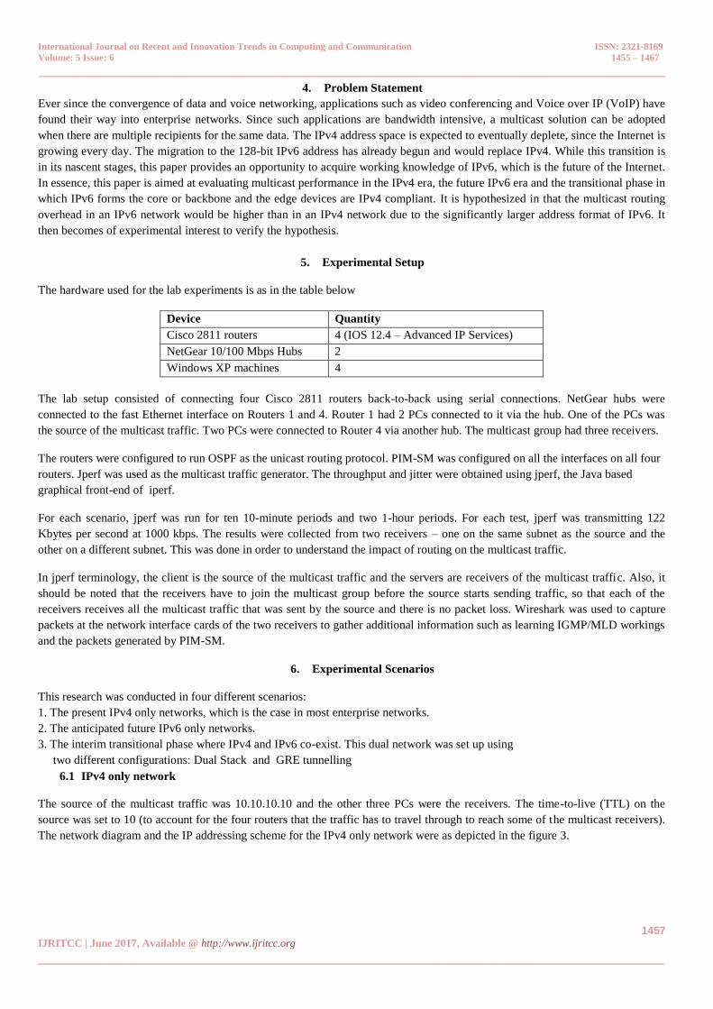
6.1 IPv4 only network
The source of the multicast traffic was 10.10.10.10 and the other three PCs were the receivers. The time-to-live (TTL) on the
source was set to 10 (to account for the four routers that the traffic has to travel through to reach some of the multicast receivers).
The network diagram and the IP addressing scheme for the IPv4 only network were as depicted in the figure 3.

International Journal on Recent and Innovation Trends in Computing and Communication ISSN: 2321-8169
Volume: 5 Issue: 6 1455 – 1467
_______________________________________________________________________________________________
1458 IJRITCC | June 2017, Available @ http://www.ijritcc.org _______________________________________________________________________________________
Figure 3: IPv4 only network diagram and addressing scheme
6.2 IPv6 only network
The IPv6 network connectivity and addressing scheme are shown in the figure 4.
Figure 4: IPv6 only network diagram and addressing scheme
The source of the multicast traffic was 2001:175::10 and the other three PCs were the receivers. The time-to-live (TTL) on the
source was set to 10 (to account for the four routers that the traffic has to travel through to reach some of the multicast receivers).
6.3 IPv4-IPv6 network – Dual-stack
In this scenario, the hosts and routers were configured with both IPv4 and IPv6 addresses. The multicast source generated two
separate multicast streams – one for IPv4 and one for IPv6. Router R4 had an IPv4 receiver and an IPv6 receiver. The network
diagram and IPv4/v6 addressing scheme were shown in figure 5.
International Journal on Recent and Innovation Trends in Computing and Communication ISSN: 2321-8169
Volume: 5 Issue: 6 1455 – 1467
_______________________________________________________________________________________________
1459 IJRITCC | June 2017, Available @ http://www.ijritcc.org _______________________________________________________________________________________
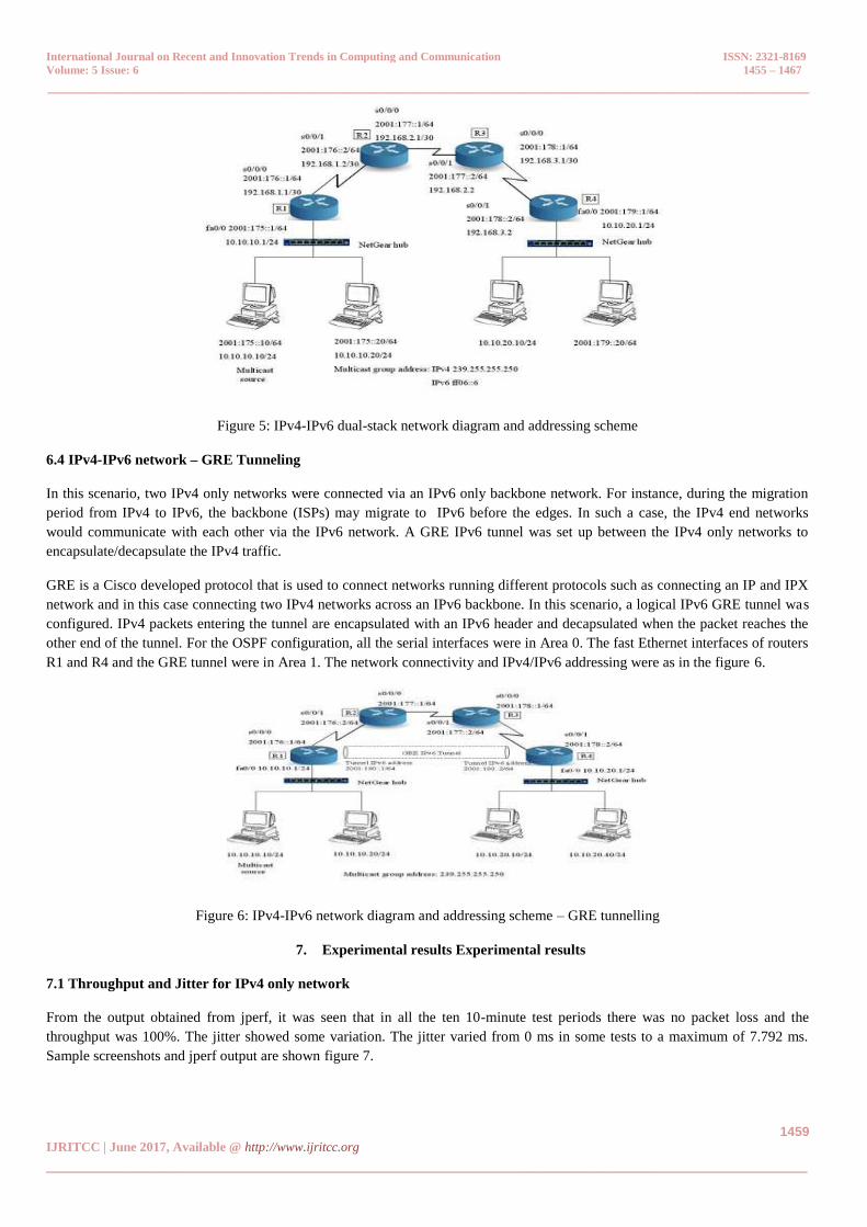
Figure 5: IPv4-IPv6 dual-stack network diagram and addressing scheme
6.4 IPv4-IPv6 network – GRE Tunneling
In this scenario, two IPv4 only networks were connected via an IPv6 only backbone network. For instance, during the migration
period from IPv4 to IPv6, the backbone (ISPs) may migrate to IPv6 before the edges. In such a case, the IPv4 end networks
would communicate with each other via the IPv6 network. A GRE IPv6 tunnel was set up between the IPv4 only networks to
encapsulate/decapsulate the IPv4 traffic.
GRE is a Cisco developed protocol that is used to connect networks running different protocols such as connecting an IP and IPX
network and in this case connecting two IPv4 networks across an IPv6 backbone. In this scenario, a logical IPv6 GRE tunnel was
configured. IPv4 packets entering the tunnel are encapsulated with an IPv6 header and decapsulated when the packet reaches the
other end of the tunnel. For the OSPF configuration, all the serial interfaces were in Area 0. The fast Ethernet interfaces of routers
R1 and R4 and the GRE tunnel were in Area 1. The network connectivity and IPv4/IPv6 addressing were as in the figure 6.
Figure 6: IPv4-IPv6 network diagram and addressing scheme – GRE tunnelling
7. Experimental results Experimental results
7.1 Throughput and Jitter for IPv4 only network
From the output obtained from jperf, it was seen that in all the ten 10-minute test periods there was no packet loss and the
throughput was 100%. The jitter showed some variation. The jitter varied from 0 ms in some tests to a maximum of 7.792 ms.
Sample screenshots and jperf output are shown figure 7.

International Journal on Recent and Innovation Trends in Computing and Communication ISSN: 2321-8169
Volume: 5 Issue: 6 1455 – 1467
_______________________________________________________________________________________________
1460 IJRITCC | June 2017, Available @ http://www.ijritcc.org _______________________________________________________________________________________
Figure 7: IPv4 Multicast Source
The graphical output from jperf was captured at different points during the 10-minute period. It provides a real-time graph of the
bandwidth and jitter. A sample of the screenshot is provided below figure 8.
Figure 8: Sample jperf screenshot from IPv4 multicast receiver
It can be observed from the output above, that over the 10-minute period, 73.244 MB of data was transferred at 1 Mbps. The jitter
was 7.792 ms. The packet loss is 0% which implies a 100% throughput. Two 1-hour test samples were also obtained from the
multicast receiver. This was to simulate a real multicast application such as a 1-hour webinar. The jitter was 0 ms and 7.817 ms
and the throughput was 100% in both the test cases.
7.2 Protocol Overheads
PIM-SM was used as the multicast routing protocol. The protocol did not produce much of an overhead (deduced from the
Wireshark captures). The PIMv2 Hello packets were sent out at 30- second intervals, as seen from time-stamps in the captured in
figure 9. Apart from these Hello packets, the protocol was not very chatty in the IPv4 network

International Journal on Recent and Innovation Trends in Computing and Communication ISSN: 2321-8169
Volume: 5 Issue: 6 1455 – 1467
_______________________________________________________________________________________________
1461 IJRITCC | June 2017, Available @ http://www.ijritcc.org _______________________________________________________________________________________
Figure 9: PIM Hello packets for IPv4 multicast
7.3 Throughput and Jitter for IPv6 only network
As in the case of the IPv4 only network, results were obtained from a multicast receiver for ten 10-minute tests and two 1-hour
tests. It can be inferred from the results that IPv6 multicast does not introduce any significantly higher jitter or packet loss than in
the case of an IPv4 only network. During the ten 10-minute tests, the jitter ranged from 0 ms to 9.487 ms. The throughput was
100% in all the ten tests. From these tests it can be concluded that the hypothesis of this research does not hold good. For the two
1-hour tests, the jitter was 0 ms in one test and 7.299 in the second test with 100% throughput in both the tests. From the output, it
can be seen that over the 10-minute period, 73.244 MB of data was transferred at 1 Mbps with 0% packet loss. The jitter was
7.305 ms. A screenshot of the live output from jperf is displayed in figure 10.
Figure 10: Sample jperf screenshot from IPv6 multicast receiver
7.4 Protocol Overheads
When compared to IPv4, there was no difference in the protocol overhead that PIM adds when running over IPv6. Similar to IPv4,
PIM sends out hello packets at 30-second intervals as can be seen from the Wireshark captured in figure 11.

International Journal on Recent and Innovation Trends in Computing and Communication ISSN: 2321-8169
Volume: 5 Issue: 6 1455 – 1467
_______________________________________________________________________________________________
1462 IJRITCC | June 2017, Available @ http://www.ijritcc.org _______________________________________________________________________________________
Figure 11: PIM Hello packets for IPv6 multicast
7.5 Throughput and Jitter for IPv4-IPv6 network – Dual-stack
For this scenario, an end-to-end dual-stack network was configured. Test outputs were obtained from an IPv4 only multicast
receiver and an IPv6 only multicast receiver. In this scenario, there was some jitter and packet loss in almost every test that was
conducted. Sample screenshots and outputs from jperf are shown figure 12.
Figure 12: Sample jperf screenshot from IPv4 multicast receiver in dual-stack network
International Journal on Recent and Innovation Trends in Computing and Communication ISSN: 2321-8169
Volume: 5 Issue: 6 1455 – 1467
_______________________________________________________________________________________________
1463 IJRITCC | June 2017, Available @ http://www.ijritcc.org _______________________________________________________________________________________
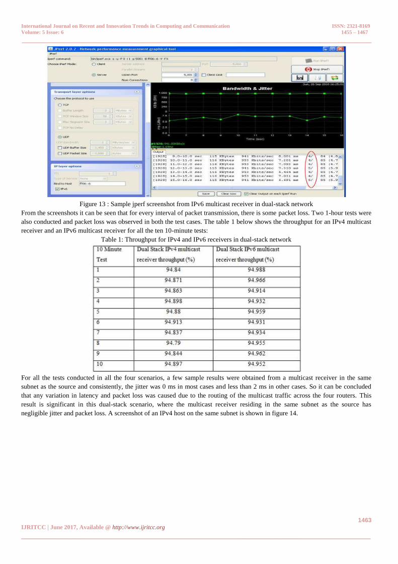
Figure 13 : Sample jperf screenshot from IPv6 multicast receiver in dual-stack network
From the screenshots it can be seen that for every interval of packet transmission, there is some packet loss. Two 1-hour tests were
also conducted and packet loss was observed in both the test cases. The table 1 below shows the throughput for an IPv4 multicast
receiver and an IPv6 multicast receiver for all the ten 10-minute tests:
Table 1: Throughput for IPv4 and IPv6 receivers in dual-stack network
For all the tests conducted in all the four scenarios, a few sample results were obtained from a multicast receiver in the same
subnet as the source and consistently, the jitter was 0 ms in most cases and less than 2 ms in other cases. So it can be concluded
that any variation in latency and packet loss was caused due to the routing of the multicast traffic across the four routers. This
result is significant in this dual-stack scenario, where the multicast receiver residing in the same subnet as the source has
negligible jitter and packet loss. A screenshot of an IPv4 host on the same subnet is shown in figure 14.

International Journal on Recent and Innovation Trends in Computing and Communication ISSN: 2321-8169
Volume: 5 Issue: 6 1455 – 1467
_______________________________________________________________________________________________
1464 IJRITCC | June 2017, Available @ http://www.ijritcc.org _______________________________________________________________________________________
Figure 14: IPv4 multicast receiver in the same subnet as the source in dual-stack network
7.6 Protocol Overheads
As in the case of the previous scenarios, the routing protocol PIM does not contribute to any significant router traffic as can be
seen from the capture below. Every 30 seconds, hello packets are exchanged and it can be seen from this Wireshark capture for
both IPv4 and IPv6 multicast.
Figure 15: PIM hello packets for IPv4-IPv6 dual-stack multicast
7.7 IPv4-IPv6 network – GRE Tunneling
This scenario is one that is most likely to occur during the interim period when the transition from an IPv4 only network to an
IPv6 only network takes place. While ISPs may start the migration, end users may not make the transition at the same pace. The
GRE tunnel was configured to route the IPv4 multicast traffic across an IPv6 backbone. Refer to Appendix for sample router
configuration.
Throughput and Jitter
Similar to an IPv4 or IPv6 only network, this network also did not have much jitter and had no packet loss during all the tests,
which can be seen from the jperf screenshot and outputs below:

International Journal on Recent and Innovation Trends in Computing and Communication ISSN: 2321-8169
Volume: 5 Issue: 6 1455 – 1467
_______________________________________________________________________________________________
1465 IJRITCC | June 2017, Available @ http://www.ijritcc.org _______________________________________________________________________________________
Figure 16: Sample jperf screenshot from IPv4 multicast receiver across GRE tunnel
7.8 Protocol Overhead
As in the case of all the scenarios, the only traffic that PIM generated was the hello packets at 30 second intervals. This can be
seen from the Wireshark capture below, where only the PIM traffic has been filtered out.
Figure 17: PIM hello packets for IPv4-IPv6 GRE tunneled network multicast
8. Graphical representation of results
The 10-minute and 1-hour test results collected from the different scenarios were plotted in graph charts.

International Journal on Recent and Innovation Trends in Computing and Communication ISSN: 2321-8169
Volume: 5 Issue: 6 1455 – 1467
_______________________________________________________________________________________________
1466 IJRITCC | June 2017, Available @ http://www.ijritcc.org _______________________________________________________________________________________
Figure 18: 10-minute multicast tests for IPv4, IPv6 and GRE tunneled networks
Figure 19: 10-minute multicast tests for dual-stack network
Figure 20: 1-hr multicast tests for IPv4, IPv6 and GRE tunneled networks

International Journal on Recent and Innovation Trends in Computing and Communication ISSN: 2321-8169
Volume: 5 Issue: 6 1455 – 1467
_______________________________________________________________________________________________
1467 IJRITCC | June 2017, Available @ http://www.ijritcc.org _______________________________________________________________________________________
Figure 21: 1-hr multicast tests for dual-stack network
9. Conclusions
The same set of outputs was gathered from an all IPv4 and an all IPv6 network. While the difference in the results is not
significantly different, the results disprove the hypothesis of this paper that the protocol overhead, jitter and throughput in an IPv6
network would be significantly larger than an IPv4 network, due to its larger address space. The protocol overheads in both the
networks remained the same. In the experiments conducted in this paper, the payload in the case of IPv4 and IPv6 was kept
constant. The interface Maximum Transfer Units (MTUs) were kept at their default values - PC
Network Interface Cards (NICs) had the default MTU of 1500 and the Cisco routers were also
left at the default value of 1500. In the case of IPv4, there was no fragmentation, whereas in IPv6 fragmentation was handled by
the host. Even with the additional task of fragmentation, there was no deterioration in the performance of the IPv6 network, which
proves that IPv6 handled the fragmentation efficiently. A future study could be conducted with varying MTUs/packet sizes across
the network and see how it affects the performance. Moreover, since IPv6 was designed as a replacement for IPv4, it was designed
to be better than IPv4. The IPv6 header is simpler than an IPv4 header. For instance, the options field, which is included in the
IPv4 header, is an extension in the IPv6 header. So without any options, the IPv6 header is not as complex as an IPv4 header.
Checksum, for error detection in IPv4, is eliminated in IPv6 (other layers take care of error detection).
Reference
[1] Lloret, J., Garcia, M., Canovas, A., and Turro, C. 2011. A stereoscopic video transmission algorithm for an IPTV network based on
empirical data. International Journal of Communication Systems, 24(10), pp: 1298-1329.
[2] Multicasting White Paper. 2009. Retrieved from Allied Telesis, available at
https://www.alliedtelesis.com/sites/default/files/multicasting_wp_0.pdf
[3] S.E. Deering, Multicast routing in internetworks and extended LANs. Stanford, CA: ACM, 1988, pp. 55-64
[4] Yuji IMAI, Hiro KISHIM0TO, Myung-Ki SHIN and Young-Han KIM, “XCAST6: eXplicit Multicast on IPv6,” in Proceedings of the
2003 Symposium On Applications and the Internet Workshops, 2003, pp. 238
[5] Narayan, S., Kolahi, S.S., Sunarto, Y., Nguyen, D. and Mani, P, “Performance comparison of IPv4 and IPv6 on various Windows
Operating Systems,” in Computer and Information Technology, 11th International Conference, 2008, pp. 663-668
[6] RFC 4601 Protocol Independent Multicast - Sparse Mode (PIM – SM): Protocol Specification, August 2006


![[Attack]tive Directory - Triangle InfoSeCon€¦ · Network -> DNS ClientEnable Turn Off Multicast Name Resolution ⬡NBT-NS: Network Connection Properties -> TCP/IPv4 -> Advanced,](https://static.fdocuments.in/doc/165x107/5fcd3f035c0dfe081447abce/attacktive-directory-triangle-infosecon-network-dns-clientenable-turn.jpg)