IMPLEMENTATION OF MRAC, SVMPC AND PID CONTROL...
28
IMPLEMENTATION OF MRAC, SVMPC AND PID CONTROL BASED ON DIRECT DIGITAL CONTROL APPLICATION FOR DC SERVOMOTOR SALEHA BTE MOHAMAD SALEH A project report submitted in partial fulfillment of the requirement for the award of the degree of Master of Engineering (Electrical - Mechatronics & Automatic Control) Faculty of Electrical Engineering Universiti Teknologi Malaysia NOVEMBER, 2005
-
Upload
truongngoc -
Category
Documents
-
view
214 -
download
0
Transcript of IMPLEMENTATION OF MRAC, SVMPC AND PID CONTROL...
IMPLEMENTATION OF MRAC, SVMPC AND PID CONTROL BASED ON
DIRECT DIGITAL CONTROL APPLICATION FOR DC SERVOMOTOR
SALEHA BTE MOHAMAD SALEH
A project report submitted in partial fulfillment
of the requirement for the award of the degree of
Master of Engineering
(Electrical - Mechatronics & Automatic Control)
Faculty of Electrical Engineering
Universiti Teknologi Malaysia
NOVEMBER, 2005

iii
To my husband, Zairulazha.
Thanks for your tremendous love and support.
I owe a lot to you.
iv
ACKNOWLEDGEMENT
Alhamdulillah, a lot of praise and ‘syukur’ to ALLAH. I wish to express my sincere
gratitude and appreciation to my supervisor, Associate Professor Dr. Mohd. Fua’ad
bin Haji Rahmat for giving me a chance to handle this project. Without his never-
ending guidance, patience and encouragement throughout this project, I would never
finish the thesis as it is. Thank you very much! Not forget to the laboratory assistant,
Mr. Fazli, who spends time to help my researches in the lab.
I would like to thank the Kolej Universiti Teknikal Kebangsaan Malaysia
(KUTKM) for sponsoring my study in the form of a scholarship. I also would like to
thank Mr. Mohd. Ariff Mat Hanafiah and Mr. Syed Najib Syed Salim, to whom I
owe thanks for helping me, secure the scholarship.
A very special thanks to my beloved parents, Mariah Abdullah and Mohamad
Saleh Ahmad, for their enduring patience, understanding and for all the pray.
Without both of you, I do not think that I can get through this. Last but not least, I
would like to use this opportunity to say thank you to my beloved brother and his
wife, Mohamad Nor, for taking care of our mum and dad. Finally, I would like to
express my appreciation to all my friends, especially to Zuraida and Herdawati,
thanks for your love and constant moral support.
Thank you to all of you
Assalamualaikum.
v
ABSTRACT
The project focused on speed control of DC servomotor under load variation
using Direct Digital Control technique. The main objective is to design and develop
GUI software for speed control experiment, where Single Variable Model Predictive
Control (SVMPC), Model Reference Adaptive Control (MRAC) and PID
controllers’ design approaches has been applied. The main purpose of using the
SVMPC is to achieve perfect control using an Internal Model Control (IMC) strategy.
The desired behavior of the adaptive controller is expressed by utilizing reference
model, and the algorithms have been realized using the Lyapunov method and MIT
rules.
The Direct Digital Control approach is selected to replace the conventional
method regarding on controlling the speed of DC motor because of its advantages in
terms of cost reduction, simplicity, flexibility and give better performance than
previous one. The original speed control experiment is conducted and data is
recorded. Based on the information that been gathered, the controllers have been
designed and the system is simulated using MATLAB to analyze their initial
performance. The computer is connected to MS150 Modular Servo System via
AX5412 data acquisition card and Microsoft Visual Basic 6.0 is used to conduct the
experiment. Field-testing is implemented to compare the results between the original
and modified system within three types of controller. Finally, the performance of the
system is analyzed and validation is done in terms of time response, robustness and
percentage of error.
vi
ABSTRAK
Projek ini memfokuskan kepada sistem kawalan halaju bagi motor servo arus terus
yang dikenakan pelbagai beban dengan menggunakan teknik kawalan digital secara
langsung. Objektif utama projek ini adalah untuk merekabentuk dan membangunkan
perisian interaktif komputer untuk ujikaji sistem kawalan halaju, di mana teknik
Kawalan Model Ramalan bagi satu pembolehubah, Kawalan Adaptasi Model
Rujukan dan Kawalan PID diaplikasikan bagi rekabentuk sistem kawalan untuk
motor tersebut. Matlamat utama menggunakan Kawalan Model Ramalan bagi satu
pembolehubah adalah untuk mendapatkan kawalan sempurna dengan menggunakan
strategi Kawalan Model Dalaman (IMC). Manakala sifat kawalan yang dikehendaki
diterjemahkan dalam bentuk model rujukan dengan menggunakan kaedah Lyapunov
dan aturan MIT.
Teknik kawalan digital secara langsung dipilih untuk menggantikan kaedah
lama dalam pengawalan halaju bagi motor arus terus kerana kelebihan-kelebihannya
iaitu dari aspek pengurangan kos, fleksible, mudah dan memberikan prestasi yang
lebih baik dari kaedah terdahulu. Eksperimen asal bagi kawalan halaju telah
dijalankan dan data-datanya telah direkodkan. Berdasarkan daripada maklumat yang
didapati, sistem kawalan telah direkabentuk dan simulasi bagi sistem dilakukan
untuk menilai prestasi asal dengan menggunakan perisian MATLAB. Komputer
telah disambungkan kepada sistem servo MS150 menerusi kad DAQ dan perisian
Microsoft Visual Basic 6.0 telah digunakan untuk menjalankan eksperimen. Ujian
terhadap sistem dijalankan untuk tujuan perbandingan di antara sistem asal dengan
sistem yang telah diubahsuai. Prestasi sistem dianalisa dan pengesahan telah dibuat
dari aspek tindakbalas masa, ketegapannya dan peratus sisihan dengan nilai yang
dikehendaki.
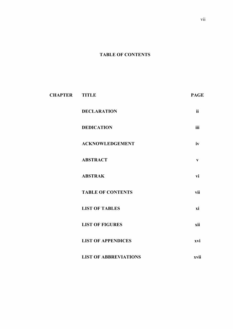
vii
TABLE OF CONTENTS
CHAPTER TITLE PAGE
DECLARATION ii
DEDICATION iii
ACKNOWLEDGEMENT iv
ABSTRACT v
ABSTRAK vi
TABLE OF CONTENTS vii
LIST OF TABLES xi
LIST OF FIGURES xii
LIST OF APPENDICES xvi
LIST OF ABBREVIATIONS xvii
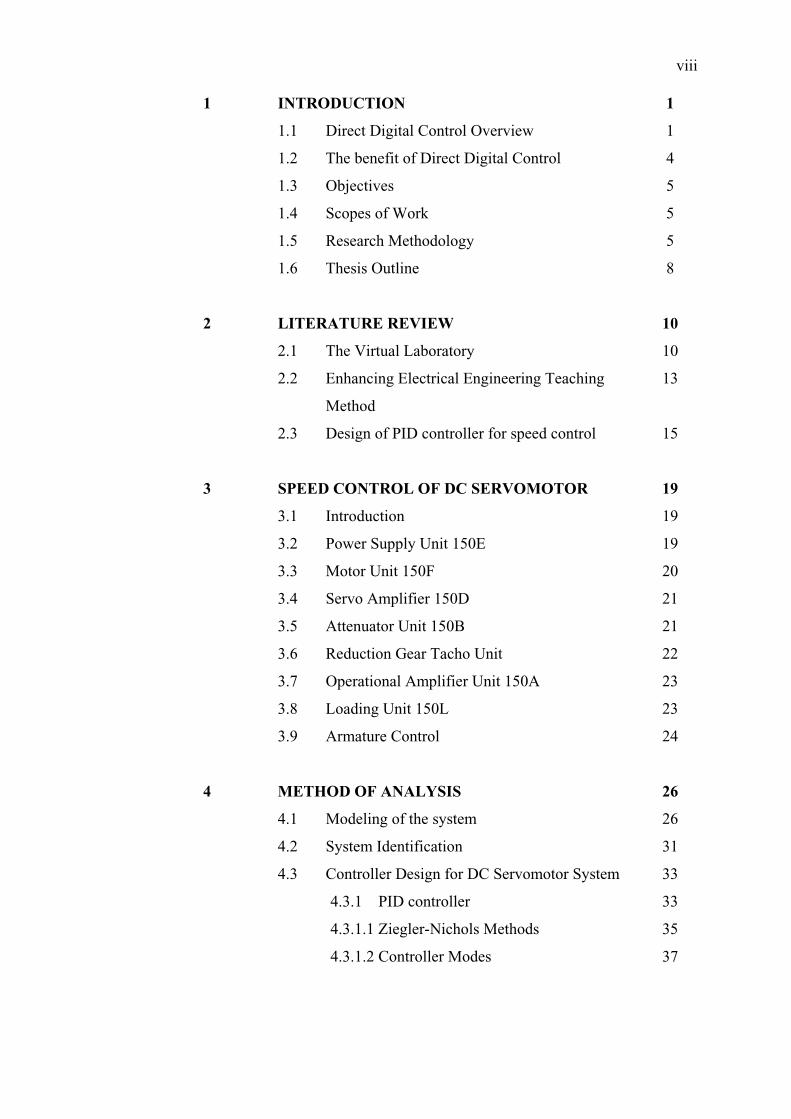
viii
1 INTRODUCTION 1
1.1 Direct Digital Control Overview
1.2 The benefit of Direct Digital Control
1.3 Objectives
1.4 Scopes of Work
1.5 Research Methodology
1.6 Thesis Outline
1
4
5
5
5
8
2 LITERATURE REVIEW 10
2.1 The Virtual Laboratory
2.2 Enhancing Electrical Engineering Teaching
Method
2.3 Design of PID controller for speed control
10
13
15
3 SPEED CONTROL OF DC SERVOMOTOR 19
3.1 Introduction
3.2 Power Supply Unit 150E
3.3 Motor Unit 150F
3.4 Servo Amplifier 150D
3.5 Attenuator Unit 150B
3.6 Reduction Gear Tacho Unit
3.7 Operational Amplifier Unit 150A
3.8 Loading Unit 150L
3.9 Armature Control
19
19
20
21
21
22
23
23
24
4 METHOD OF ANALYSIS 26
4.1 Modeling of the system
4.2 System Identification
4.3 Controller Design for DC Servomotor System
4.3.1 PID controller
4.3.1.1 Ziegler-Nichols Methods
4.3.1.2 Controller Modes
26
31
33
33
35
37
ix
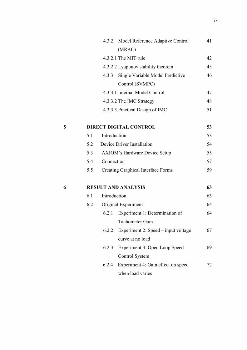
4.3.2 Model Reference Adaptive Control
(MRAC)
4.3.2.1 The MIT rule
4.3.2.2 Lyapunov stability theorem
4.3.3 Single Variable Model Predictive
Control (SVMPC)
4.3.3.1 Internal Model Control
4.3.3.2 The IMC Strategy
4.3.3.3 Practical Design of IMC
41
42
45
46
47
48
51
5 DIRECT DIGITAL CONTROL 53
5.1 Introduction
5.2 Device Driver Installation
5.3 AXIOM’s Hardware Device Setup
5.4 Connection
5.5 Creating Graphical Interface Forms
53
54
55
57
59
6 RESULT AND ANALYSIS 63
6.1 Introduction
6.2 Original Experiment
6.2.1 Experiment 1: Determination of
Tachometer Gain
6.2.2 Experiment 2: Speed – input voltage
curve at no load
6.2.3 Experiment 3: Open Loop Speed
Control System
6.2.4 6.2.4 Experiment 4: Gain effect on speed
when load varies
63
64
64
67
69
72
x
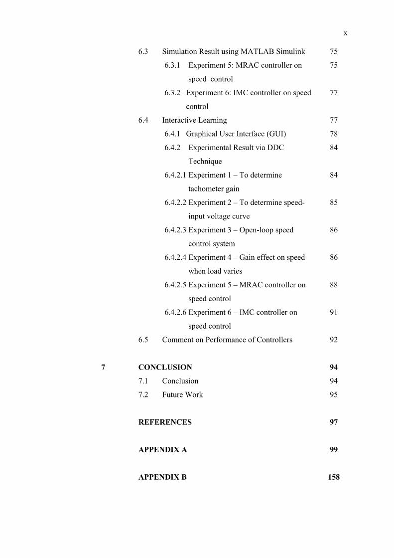
6.3 Simulation Result using MATLAB Simulink
6.3.1 Experiment 5: MRAC controller on
speed control
6.3.2 Experiment 6: IMC controller on speed
control
6.4 Interactive Learning
6.4.1 Graphical User Interface (GUI)
6.4.2 Experimental Result via DDC
Technique
6.4.2.1 Experiment 1 – To determine
tachometer gain
6.4.2.2 Experiment 2 – To determine speed-
input voltage curve
6.4.2.3 Experiment 3 – Open-loop speed
control system
6.4.2.4 Experiment 4 – Gain effect on speed
when load varies
6.4.2.5 Experiment 5 – MRAC controller on
speed control
6.4.2.6 Experiment 6 – IMC controller on
speed control
6.5 Comment on Performance of Controllers
75
75
77
77
78
84
84
85
86
86
88
91
92
7 CONCLUSION 94
7.1 Conclusion
7.2 Future Work
94
95
REFERENCES 97
APPENDIX A 99
APPENDIX B 158

xi
LIST OF TABLES
TABLE DESCRIPTION PAGE
2.1 Advantages of a Virtual Laboratory 11
4.1 Ziegler Nichols Rules 36
5.1 Action between modules 62
6.1 Result for Experiment 1 66
6.2 Result for Experiment 2 68
6.3 Result for Experiment 3 (Attenuator at position ‘10’;
Vin = 14.41V)
70
6.4 Result for Experiment 3 (Attenuator at position ‘1’;
Vin = 0.8V)
70
6.5 Result for Experiment 4 (Gain = 1 (Attenuator at
position 10))
73
6.6 Table for Experiment 4 (Gain = 5 (Attenuator at position
1))
73
6.7 Comparison regarding on the performances among P,
PD, PI and PID controllers
87
6.8 Comparison regarding on the controller’s performance 92

xii
LIST OF FIGURES
FIGURE DESCRIPTION PAGE
1.1 Equipment Setup 2
1.2 Block Diagram Comparison (a) The Original Closed
Loop Speed Control System (b) The Modified Closed
Loop Speed Control System
3
1.3 Components that been eliminated (a) attenuator (b)
operational amplifier (c) oscilloscope
4
1.4 Design flow 7
2.1 Hardware structure of the virtual laboratory 12
2.2 PID controller 16
2.3 Control system block diagram 18
3.1 Power Supply Unit 20
3.2 DC Motor Unit 20
3.3 Servo Amplifier Unit 21
3.4 Attenuator Unit 22
3.5 Tachogenerator Unit 22
3.6 Operational Amplifier Unit 23
3.7 Loading Unit 24
3.8 Equipments of speed control of dc servomotor 24
3.9 Armature Control 25
3.10 Speed vs. Voltage 25
3.11 Speed vs. Torque 25

xiii
4.1 Armature-controlled dc motor with load 26
4.2 Block diagram of a dc motor (armature-controlled)
system
28
4.3 Block diagram of the system (a) Open loop system
(b) Closed loop system
30
4.4 Input output form 31
4.5 Identification of the system 32
4.6 S-shape response curve 36
4.7 P-controller algorithm (with sampling period is about
50 ms)
37
4.8 PI-controller algorithm (with sampling period is
about 50 ms, Ti = 50 ms and KI = KP * Ts/Ti)
38
4.9 PD-controller algorithm (with sampling period is
about 50 ms, Td = 50 ms and KD = KP * Td/Ts)
39
4.10 PID-controller algorithm (with sampling period is
about 50 ms, Td = 50 ms, Td = 50 ms, KI = KP *
Ts/Ti and KD = KP * Td/Ts)
40
4.11 Block diagram of an adaptive system 41
4.12 Block diagram of a model reference adaptive control 42
4.13 MRAC using the MIT rule’s algorithm 44
4.14 MRAC using the Lyapunov’s stability theory 46
4.15 Open loop control strategy 47
4.16 Schematic of the IMC scheme 48
4.17 Internal Model Control (IMC) algorithm 52
5.1 AX5412 Data Acquisition Card 54
5.2 Device Manager Window 55
5.3 Device setting 56
5.4 Base Address Switch Setting 54
5.5 AX5412 (CN1) Pin Assignment 58
5.6 Hardware connection 59
5.7 Communication between modules 61
6.1 Overall Project 64
6.2 Connection for Experiment 1 65
xiv
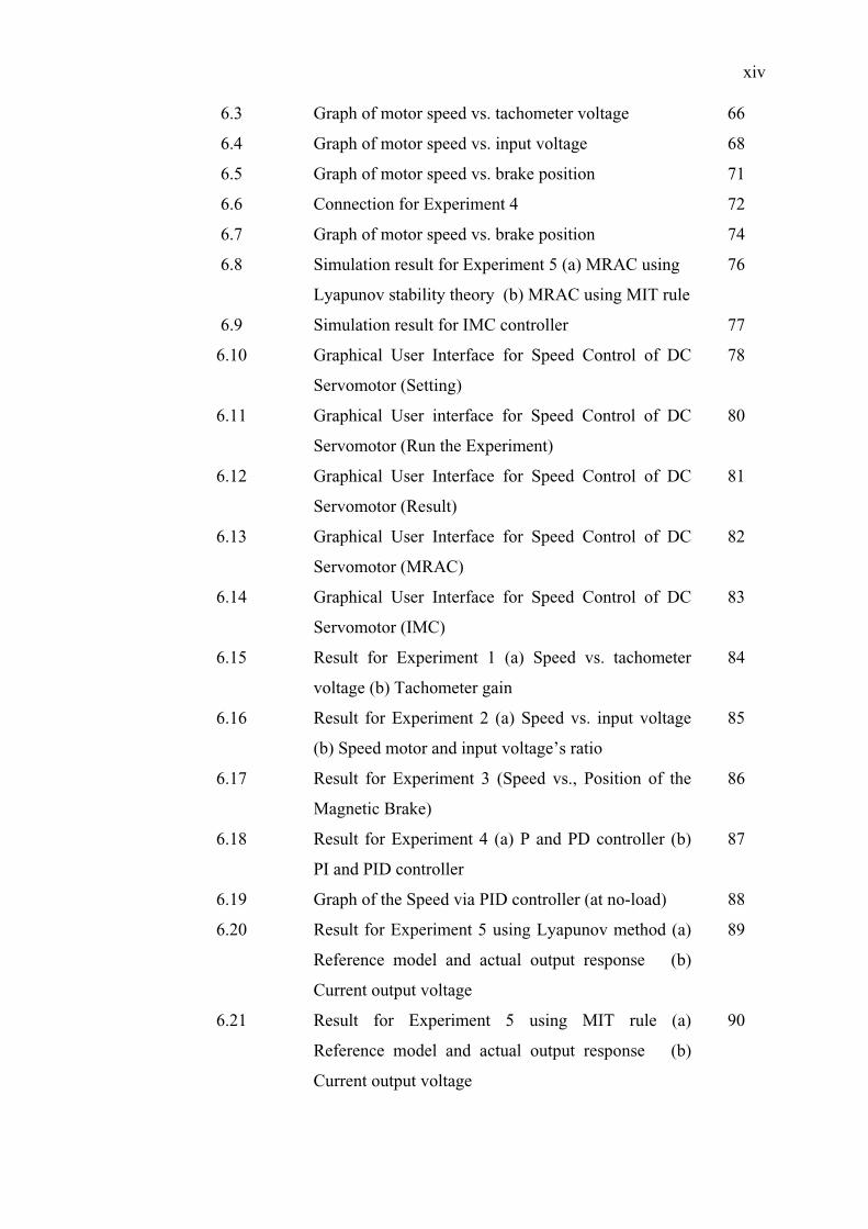
6.3 Graph of motor speed vs. tachometer voltage 66
6.4 Graph of motor speed vs. input voltage 68
6.5 Graph of motor speed vs. brake position 71
6.6 Connection for Experiment 4 72
6.7 Graph of motor speed vs. brake position 74
6.8 Simulation result for Experiment 5 (a) MRAC using
Lyapunov stability theory (b) MRAC using MIT rule
76
6.9 Simulation result for IMC controller 77
6.10 Graphical User Interface for Speed Control of DC
Servomotor (Setting)
78
6.11 Graphical User interface for Speed Control of DC
Servomotor (Run the Experiment)
80
6.12 Graphical User Interface for Speed Control of DC
Servomotor (Result)
81
6.13 Graphical User Interface for Speed Control of DC
Servomotor (MRAC)
82
6.14 Graphical User Interface for Speed Control of DC
Servomotor (IMC)
83
6.15 Result for Experiment 1 (a) Speed vs. tachometer
voltage (b) Tachometer gain
84
6.16 Result for Experiment 2 (a) Speed vs. input voltage
(b) Speed motor and input voltage’s ratio
85
6.17 Result for Experiment 3 (Speed vs., Position of the
Magnetic Brake)
86
6.18 Result for Experiment 4 (a) P and PD controller (b)
PI and PID controller
87
6.19 Graph of the Speed via PID controller (at no-load) 88
6.20 Result for Experiment 5 using Lyapunov method (a)
Reference model and actual output response (b)
Current output voltage
89
6.21 Result for Experiment 5 using MIT rule (a)
Reference model and actual output response (b)
Current output voltage
90

xv
6.22 Result for Experiment 6 (a) Reference model and
actual output response (b) Desired output (c)
Current output
91
xvi
LIST OF APPENDICES
APPENDIX DESCRIPTION PAGE
Appendix A Software Source Code 99
Appendix B Formula Derivation 158
xvii
LIST OF ABBREVIATIONS
ADC - Analog-Digital Converter
API - Application Program Interface
DAC - Digital-Analog Converter
CD - Compact Disc
CN - Connector
CV - Control Variable
DAS - Data Acquisition System
DAQ - Data Acquisition
DC - Direct Current
DDC - Direct Digital Control
Err - Error
GPIB - General Purpose Interface Bus
GUI - Graphical User Interface
IMC - Internal Model Control
I/O - Input / Output
J - Loss function
LSLNR - Linear System Learner
MIMO - Multi Input Multi Output
MIT - Massachusetts Institute of Technology
MPC - Model Predictive Control
MRAC - Model Reference Adaptive Control
OS - Overshoot; operating system
PC - Personal Computer
PCI - Peripheral Component Interface
PI - Proportional-Integral
PID - Proportional-Integral-Derivative
xviii
PLC - Programmable Logic Control
PV - Process Variable
OOP - Object-Oriented Programming
O/P - Output
ISA - Integrated System Architecture
SP - Set point
SVMPC - Single Variable Model Predictive Control
tp - Peak Time
ts - Settling Time
VB - Visual Basic
Ve - Error Voltage
Vg - Tachometer voltage
Vin - Input voltage
rpm - rotation per minute
CHAPTER I
INTRODUCTION
1.2 Direct Digital Control Overview
The major change occurring at the present is the increasing number of user
friendly software that make it possible for student to experience new and fast ways of
learning. In minutes, simulation, controller and real world interfacing can be created.
The software package is developed to help students to learn and explore the
experiment with an interesting way. A picture worth a thousand words.
In DDC, the control laws are implemented in a digital computer as a
computer programs. In realizing a real time computer controlled system in which a
digital computer, specifically a microcomputer or PC is one of the major component
that acts as a controller in the control loop [1]. The computer must be connected
somehow to the external event and the program instructions are necessary to direct
the interaction between the computer and the external activity.
2
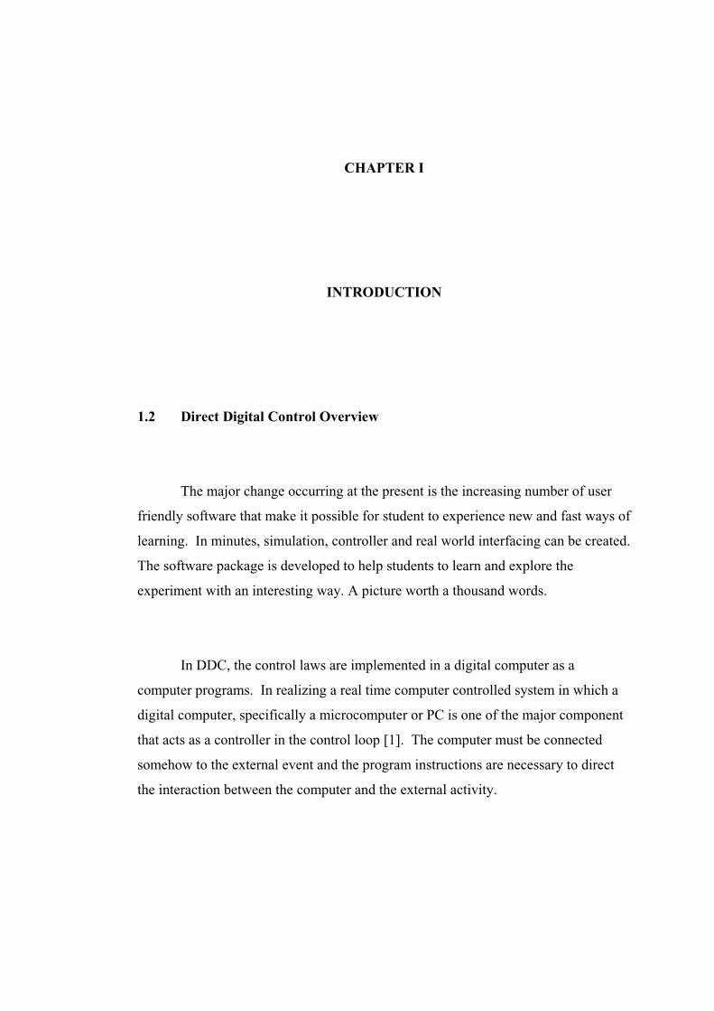
There are two major parts:
Hardware Interfacing – connecting the computer to external equipment.
Figure 1.1 shows the equipment setup for this project
Software Design – programming the computer to carry out its control
calculation (control laws) while interacting with external components. Visual
Basic will be used to program the DAS board since this program is easy to
learn it’s code programming and user friendly
Figure 1.1: Equipment Setup
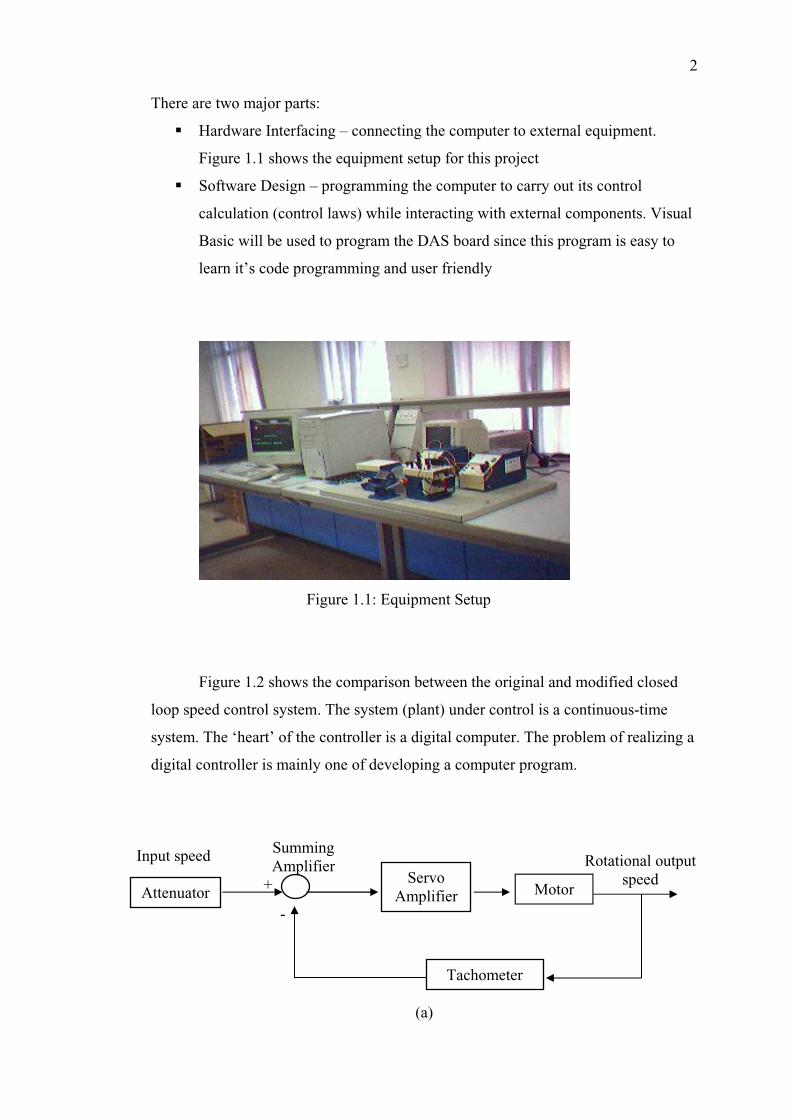
ure 1.2 sh ws the comparis the original and modified closed
loop speed control system. The system (pl a continuous-time
system. The ‘heart’ of the controller is a di ital computer. The problem of realizing a
digital controller is mainly one of developing a com .
(a)
Fig o on between
ant) under control is
g
puter program
Input speed
AttenuatorServomplifierA Motor
Tachometer
Summingfier
-
Ampli+
Rotatiospeed
nal output
3
res.
g controllers, any change in the characteristics of the controller is
sually laborious and expensive, since it requires changes in the structure and the
lements of the controller. In digital controller, the designer has the flexibility to use
e same hardware equipment to realize and test different control algorithms. This
an be done because only the program that realizes the control algorithm has to be
hanged for every controller realization. However, the performance of the digital
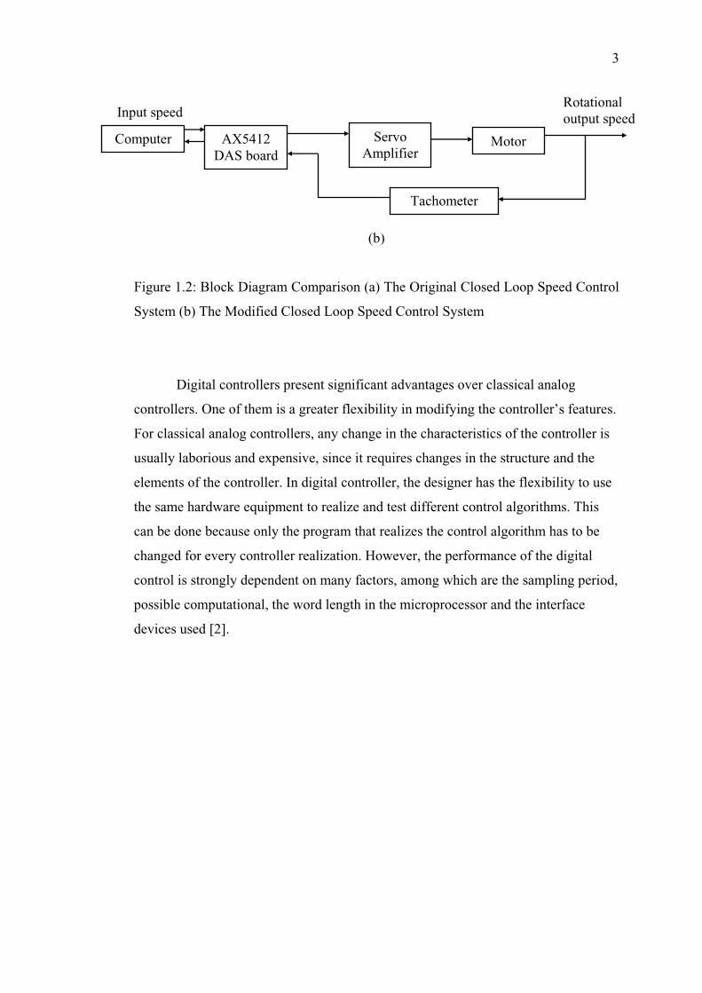
control is strongly dependent on many fact rs, among which are the sampling period,
possible computational, the word length in the microprocessor and the interface
devices used [2].
ut speed
(b)
Figure 1.2: Block Diagram Comparison (a) The Original Closed Loop Speed Control
System (b) The Modified Closed Loop Speed Control System
Digital controllers present significant advantages over classical analog
controllers. One of them is a greater flexibility in modifying the controller’s featu
For classical analo
u
e
th
c
c
o
Inp
Computer ServoAmplifier
Motor
Tachometer
AX5412DAS board
Rotationaloutput speed

4
1.2
enefit of using DDC are listed below:
Performance
t is
will not be exactly the nominal values. Meanwhile, by
using DDC technique the controller gain is exactly the value set by user
ii.
iii.
he number of hardware will be redu e contro
lace in software. Figure 1.3 shows the components that will be eliminated in
losed-loop speed control system and replace by software. It permits fast and
ce the
associated control law can simply be programmed.
(c)
Figure 1.3: Co ts that been eliminated (a) attenuator (b) operational amplifier
(c) oscilloscope
The benefit of Direct Digital Control
B
i. Improve Accuracy and
The gain provided by connecting operational amplifier and attenuator uni
different with the gain calculated because the tolerance of the gain defining
resistor values, which
Improve Effectiveness
By using DDC method, it is more flexible in changing set points and the
overall control logic. Students are able to see system response through the
virtual oscilloscope
Reduce Cost
T ced since th ller function takes
p
c
low cost implementation of even more sophisticated control system sin
(a) (b)
mponen

5
1.3 Object
The ob
i. To apply Direct Digital Control technique on the speed control of DC
motor.
ii. To improve the system performance through designing and tuning of
the controllers.
aphical user interface (GUI) for speed control
experiment and analyze the system response.
1.4 Scopes
i. trol method towards controlling speed
of DC motor.
ii. Implementing the proposed controller: MRAC, SVMPC and PID.
iii. Designing the programming structure for controller via Microsoft
Visual Basic 6.0.
cquisition Board to interface between the
computer and DC Servomotor.
1.5 Research Methodology
. Also
e theory of conventional controllers.
ives
jectives of this project are as follows:
iii. To design a gr
of Work
Applying the Direct Digital Con
iv. Using AX5412 Data A
Literature review to understand the concept and identify the
techniques, problems and current works.
ii. Define the modeling and the method will be used for the system
understand th
6
iii. n and MATLAB simulation of the system.
v. s.
vi. Design and writing program to modify the system using DDC
application.
through DAS card.
viii. Field-testing is conducted to compare the results between the original
and modified system. Analyze the system’s performance.
esign steps of work methodology can be simplified as shown in Figure 1.4.
System identificatio
iv. Conducting the procedures of the original system and get the results.
Learn up VB programming and the Axiom driver function
vii. Interface with hardware between computer and DC servomotor
D

7
Figure 1.4: Design flow
ConclusionC& Analysisomparison
Objective
OriginalExperiment
Writing VB program
Visual Basic Software
Study / Review
Integration with Hardware
Hardware Connection & DAQ Card Installation
Simulation using MATLAB
Previous Works from others
Theory
Identify the system
FulfillSpec?
Yes
No

8
hapter 1: Introduction
introduction to the project report, objectives, scope of
works a ftware
hapter 2: Literature Review
w on the Virtual Laboratory,
Enh
hapter 3: Speed Control of DC Servomotor
explained through this chapter. The DC servomotor
prin
hapter 4: Method of Analysis
l be introduced in this chapter. Starting with
modeli s
hapter 5: Direct Digital Control
This chapter will explain how the Direct Digital Control application will be
luding the installation and connection of the devices.
1.6 Thesis Outline
C
This chapter gives the
nd methodology taken. It also described briefly the hardware and so
used in completing this project.
C
This chapter covers the literature revie
ancing Electrical Engineering Teaching Method and Design of PID controller for
speed control, how it works and its components.
C
DC Servomotor devices are
ciple of operation is discussed. Device characteristics and functions are also
included.
C
There are several concepts wil
ng of the system, discretize the analog controller and parameter tuning proces
of PID. MRAC and IMC controller design implementation.
C
implemented in this project. Inc

9
he results are determined through the original experiments of the speed
control, simulation and through the experiment where the used apparatus has been
been an
Chapter 7: Conclusion
his last chapter presented the overall conclusion for the project. For the
future work, some suggestions have been included in order to improve the work that
has been conducted.
Chapter 6: Result & Analysis
T
modified. Analysis regarding on the performance of the controller design also has
alyzed and validated.
T
98
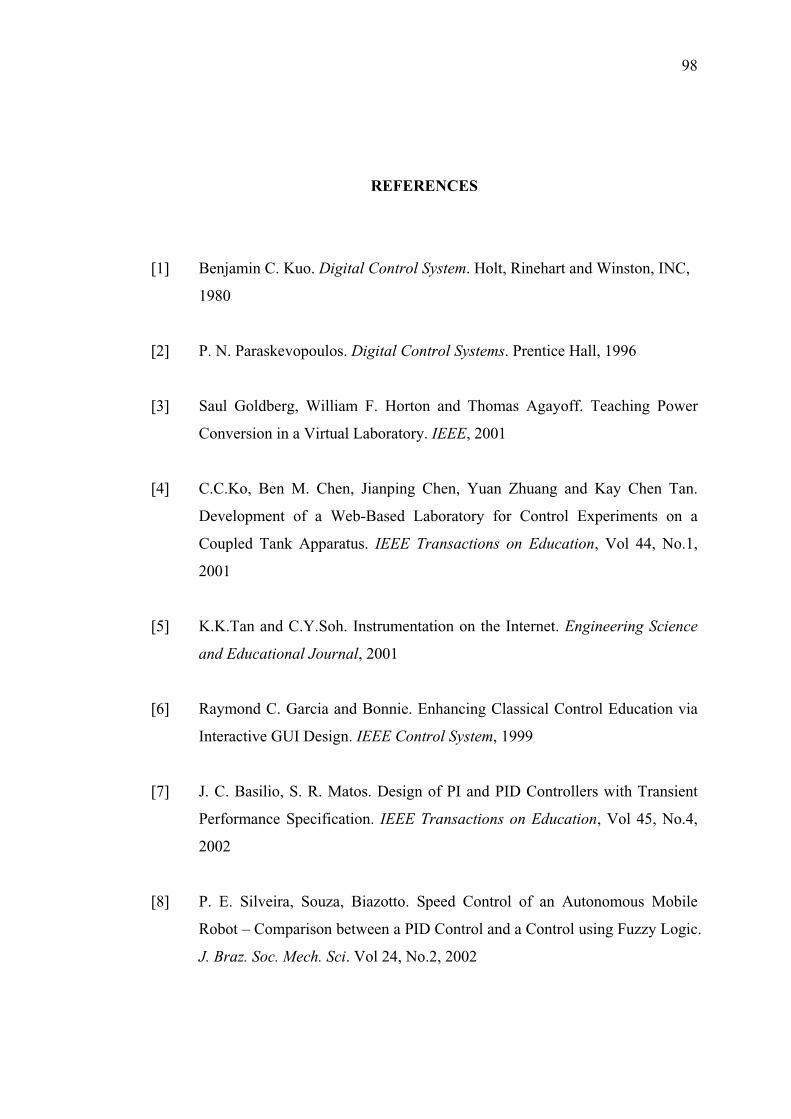
REFERENCES
[1] Control System. Holt, Rinehart and Winston, INC,
[2] Digital Control Systems. Prentice Hall, 1996
[3] Horton and Thomas Agayoff. Teaching Power
boratory. IEEE, 2001
[4] n, Jianping Chen, Yuan Zhuang and Kay Chen Tan.
evelopment of a Web-Based Laboratory for Control Experiments on a
d Tank Apparatus. IEEE Transactions on Education, Vol 44, No.1,
[5] ntation on the Internet. Engineering Science
[6] onnie. Enhancing Classical Control Education via
EE Control System, 1999
[7] asilio, S. R. Matos. Design of PI and PID Controllers with Transient
ion, Vol 45, No.4,
[8] zotto. Speed Control of an Autonomous Mobile
obot – Comparison between a PID Control and a Control using Fuzzy Logic.
z. Soc. Mech. Sci. Vol 24, No.2, 2002
Benjamin C. Kuo. Digital
1980
P. N. Paraskevopoulos.
Saul Goldberg, William F.
Conversion in a Virtual La
C.C.Ko, Ben M. Che
D
Couple
2001
K.K.Tan and C.Y.Soh. Instrume
and Educational Journal, 2001
Raymond C. Garcia and B
Interactive GUI Design. IE
J. C. B
Performance Specification. IEEE Transactions on Educat
2002
P. E. Silveira, Souza, Bia
R
J. Bra

99
[9] Modular Servo System MS150Mk2 DC, Synchro, &
[10] M. pal. Control Systems – Principle and Design. McGraw Hill, Second
002
[11] ystems Engineering. John Wiley & Sons, 2000
[12] Katsuhiko Ogata. Discrete-Time Control System. Prentice Hall, 1995
[13] D. Johnson. Process Control Instrumentation Technology. Prentice
all, 2000
[14] arl Johan Astrom and Bjorn Wittenmark. Adaptive Control. Addison-
Second Edition, 1995
[15] . Bordons. Model Predictive Control. Springer, Second
dition, 2004
[16] ntrol – Designing Processes and Control
ic Performance. Second Edition, 2000
[17] o., Ltd. AX 5412 High Speed Data Acquisition Board
nual
[18] – How to program. Prentice Hall, 1999
[19] Robert H. Bishop. Modern Control Systems. Prentice
5
Feedback Instrument Ltd.
AC Basic Experiments. Book 1
Go
Edition, 2
Norman S. Nise. Control S
Curtis
H
K
Wesley Publishing Company, Inc,
E. F. Camacho and C
E
Thomas E. Marlin. Process Co
Systems for Dynam
Axiom Technology C
User’s Ma
Deitel, T. R. Nieto. Visual Basic 6
Richard C. Dorf and
Hall, Tenth Edition, 200