Implementation of Linux GPIO Device Driver on · PDF fileImplementation of Linux GPIO Device...
70
Vu Nguyen Implementation of Linux GPIO Device Driver on Raspberry Pi Platform Helsinki Metropolia University of Applied Sciences Bachelor of Engineering Information Technology Bachelor’s Thesis 10 May 2014
Transcript of Implementation of Linux GPIO Device Driver on · PDF fileImplementation of Linux GPIO Device...

Vu Nguyen
Implementation of Linux GPIO Device Driver on Raspberry Pi Platform
Helsinki Metropolia University of Applied Sciences
Bachelor of Engineering
Information Technology
Bachelor’s Thesis
10 May 2014

Abstract
Author(s) Title Number of Pages Date
Vu Nguyen Implementation of Linux GPIO Device Driver on Raspberry Pi Platform 48 pages + 3 appendices 10 May 2014
Degree Bachelor of Engineering
Degree Programme Information Technology
Specialisation option Embedded Engineering
Instructor(s)
Markku Nuutinen, Project supervisor
The project was aimed at implementing a General Purpose Input/Output (GPIO) device driver for the Raspberry Pi model B rev 2.0 platform. Specific attention was given to im-plement the device driver based on the Linux character device driver. Each of the GPIO pins on Raspberry Pi is exposed to userspace for use by a device file in the /dev directory. While a dynamically assigned major number was used to identify the device driver associated with the GPIO device, a minor number was used by the kernel to differentiate between GPIO pins that the device driver controls. Four entry points were implemented to handle low-level hardware GPIO resources on behalf of system calls re-quested by a userspace application. Besides, interrupt handling was implemented as an experimental feature to see how a device driver supports interrupt in an embedded Linux system. The GPIO device driver could be used on the Raspberry Pi platform by loading it either as a kernel module or as an integral component of the Linux kernel. One or more userspace processes could open a device file for reading the logic level of a GPIO pin, controlling the direction of a GPIO pin, and setting its logic level to high state or low state. Besides, inter-rupt handling feature was tested; the result showed that more than one process could share an interrupt resource on a GPIO pin and could disable interrupt on that GPIO pin. There still remain, however, some limitations to the features offered by the driver. Interrupt handling is still an experimental feature. More work needs to be done to make the feature useful for use. Furthermore, the GPIO character device driver is deprecated with a newer version of the Linux kernel by the gpio-sysfs driver.
Keywords Linux GPIO driver, Raspberry Pi, Linux character driver, GPIO kernel module

Contents
1 Introduction 1
2 Theoretical Background on the Embedded Linux System of the Project 2
2.1 Raspberry Pi Model B Rev 2.0 Platform 2
2.2 Overview of Raspberry Pi GPIO Pins 3
2.3 Raspbian Linux Distribution 5
2.4 Linux Character Device Driver 8
3 Design of the GPIO Device Driver 11
3.1 Project Setup 11
3.2 Design of Per-device Structure and Initialization and Exit Routines 16
3.3 Design of the Entry Points for the GPIO Device Driver 17
3.4 Design of Interrupt Handling Functions 22
4 Implementation of the GPIO Device Driver 23
4.1 Linux Kernel Compilation and Installation 23
4.2 Implementation of Per-device Structure and Initialization and Exit Routines 26
4.3 Implementation of the Entry Points for the GPIO Device Driver 30
4.4 Implementation of Interrupt Handling Functions 35
5 Testing of the GPIO Device Driver 37
5.1 Testing Preparation 37
5.2 Testing of Output Functionality 37
5.3 Testing of Input Functionality 39
5.4 Testing of Interrupt Functionality 42
6 Results and Discussion 45
7 Conclusion 47
References 48
Appendices
Appendix 1. Source code for GPIO Linux device driver
Appendix 2. Source code for output testing of GPIO device driver
Appendix 3. Source code for input testing of GPIO device driver

List of Abbreviations
API Application programming interface
DHCP Dynamic host configuration protocol
DMM Digital multimeter
DNS Domain name system
FAT File allocation table
GCC GNU compiler collection
GND Ground
GPIO General-purpose input/output
GPU Graphics processing unit
I2C Inter-integrated circuit
IC Integrated circuit
IDE Integrated development environment
IO Input/ouput
IP Internet protocol
IPC Inter-process communication
LAN Local area network
LED Light-emitting diode
LTS Long term support
MAC Media access control
PC Personal computer
PLD Programmable logic device
PWM Pulse-width modulation
SD Secure digital
SoC System on chip
SPI Serial peripheral interface
SSH Secure shell
UART Universal asynchronous receiver/transmitter
USB Universal serial bus
UTP Unshielded twisted pair
VFS Virtual filesystem

1
1 Introduction
Nowadays Linux is an operating system of choice for many computing systems ranging
from personal computers (PC), servers, mainframe computers and supercomputers to
electronic devices known as embedded systems. An embedded system is a computing
system which is specifically designed to carry out a set of dedicated tasks, and it typi-
cally uses a custom microcontroller as its main processing unit. Linux is a highly porta-
ble operating system; it can run on a variety of hardware architectures such as x86,
PowerPC, MIPS, H8, SPARC, or ARM, to name just a few.
This portability also comes with limitations, however. It is no doubt that while the modu-
lar architecture of Linux makes it easy when porting to different types of architectures,
a great deal of effort is required to build new kernel components in order to support a
target platform. The real hard work of these efforts is to develop device drivers for a
particular target platform. A device driver (kernel module) is a piece of software that
consists of a set of low-level interfaces, and is designed to control a hardware device.
The Raspberry Pi platform is an example of a target device that Linux can be ported to
run on it. GPIO device driver is one of the kernel components that can be developed to
support the Raspberry Pi platform. The goal of this project was to implement a GPIO
device driver for Raspberry Pi.
Specifically, attention was given to the implementation of the GPIO device driver based
on Linux character device drivers. The intended result of this work was to give a deeper
understanding on the Raspberry Pi platform, to learn what a Linux device driver does
and how it works, and finally to implement a GPIO character device driver for the
Raspberry Pi platform from scratch.
2
2 Theoretical Background on the Embedded Linux System of the Project
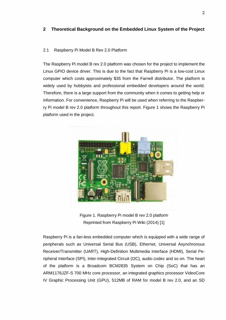
2.1 Raspberry Pi Model B Rev 2.0 Platform
The Raspberry Pi model B rev 2.0 platform was chosen for the project to implement the
Linux GPIO device driver. This is due to the fact that Raspberry Pi is a low-cost Linux
computer which costs approximately $35 from the Farnell distributor. The platform is
widely used by hobbyists and professional embedded developers around the world.
Therefore, there is a large support from the community when it comes to getting help or
information. For convenience, Raspberry Pi will be used when referring to the Raspber-
ry Pi model B rev 2.0 platform throughout this report. Figure 1 shows the Raspberry Pi
platform used in the project.
Figure 1. Raspberry Pi model B rev 2.0 platform
Reprinted from Raspberry Pi Wiki (2014) [1]
Raspberry Pi is a fan-less embedded computer which is equipped with a wide range of
peripherals such as Universal Serial Bus (USB), Ethernet, Universal Asynchronous
Receiver/Transmitter (UART), High-Definition Multimedia Interface (HDMI), Serial Pe-
ripheral Interface (SPI), Inter-Integrated Circuit (I2C), audio codec and so on. The heart
of the platform is a Broadcom BCM2835 System on Chip (SoC) that has an
ARM1176JZF-S 700 MHz core processor, an integrated graphics processor VideoCore
IV Graphic Processing Unit (GPU), 512MB of RAM for model B rev 2.0, and an SD

3
card in place of a hard disk drive [2]. The platform is powered from an external power
supply via a USB micro connector. It is recommended from the official Raspberry Pi
website that the board be powered from a good-quality power supply that gives at least
700mA at 5V [3]. This is because if the board is powered by a USB micro connector,
there will not be enough current and, as a result, the board my reboot sometimes when
it draws too much power.
2.2 Overview of Raspberry Pi GPIO Pins
Raspberry Pi comes with a 26-pin connector called P1 and an 8-pin connector called
P5. The pins on these connectors expose to users a set of buses such as I2C, SPI,
Pulse Width Modulation (PWM), and signals. There are eight GPIO pins on P1 con-
nector and four GPIO pins on P5 connector. In addition, the P1 connector has an I2C
interface which consists of two pins, a 5-wire SPI interface, and a serial interface with
two pins. These pins can be configured to be GPIO pins, thus making the total number
of GPIO pins on Raspberry Pi to be 21 pins. A point worth mentioning here is that four
GPIO pins on the P5 connector are available only on the Raspberry Pi model B rev 2.0
platform.
Figure 2. Mapping between BCM2835 GPIO pins and Raspberry Pi P5 connector
Modified from Henderson (2013) [4]
Figure 2 shows the mapping between Broadcom BCM2835 SoC's GPIO pins and the
Raspberry Pi P5 connector. The P5 connector which consists of eight pins as seen in

4
figure 2 is viewed from the bottom side of the board. Since Raspberry Pi was originally
shipped without any header on P5 connector, a double sided 2.54mm header has to be
soldered either on top or at the bottom of the board for use.
Figure 3. Mapping between BCM2835 GPIO pins and Raspberry Pi P1 connectors
Modified from Henderson (2013) [4]
As can be seen from figure 3, the pins on the P1 connector, on the other hand, are
viewed looking at the platform from above with the USB micro connector at the top-left
to the Raspberry Pi and P1 connector to the top-right of the platform.
5
As the name implies, GPIO is a general-purpose pin on a chip which, whether config-
ured as input or output, can be controlled on the fly by means of software. By default, a
GPIO pin has no defined special purpose, and is not used. GPIO pins may be used in
situations where there is a need to have multiple digital control lines so that no addi-
tional circuitry is required [5]. A GPIO pin is capable of performing the following:
Can be configured as an input pin or an output pin
Can be set low or high for output GPIO pin
Can be set as input for reading digital logic level
Can be set to enable interrupt. [5.]
Due to the flexibility of GPIO pins, they are often used in a wide range of integrated
circuits (IC), SoC, embedded platforms such as Arduino, BeagleBoard, Stellaris
Launchpad, and Raspberry Pi, multiple function chips, for example audio codes and
video cards, or Programmable Logic Devices (PLD) [5]. It should be noted that GPIO
pins 2 and 3 on Raspberry Pi are initially configured as I2C interfaces with 1.8KΩ pull-
up resistors, and pin 15 being configured as a serial UART receive pin. When Raspber-
ry Pi is booting, these pins must be left unused. Otherwise, the board will not be able to
boot successfully.
2.3 Raspbian Linux Distribution
The Raspberry Pi platform includes hardware resources such as CPU, memory, In-
put/Output (I/O) peripherals, networking, and many other resources. In order to man-
age those hardware resources, a Linux kernel was utilized in the project. The Linux
kernel is one of the components of an embedded Linux system which was created by a
Finnish student named Linus Torvalds in 1991 as a hobby project. The announcement
was made by Linus in 1991 on the newsgroups comp.os.minix. Since then Linux has
made its way into a robust, reliable, and high-end operating system that can be consid-
ered to be a strong rival of closed-source operating systems. Nowadays, over 50% of
Internet services on the Internet are being run on Linux servers. [6,65.] The Linux ker-
nel is the heart of an embedded Linux system just like a processor is the heart of an
embedded system. In particular, the Linux kernel is responsible for the following tasks:

6
To manage and control a system's hardware resources (e.g. I/O, CPU,
memory)
To offer set Application Programming Interfaces (API) so that application
programs and libraries can use hardware devices
To handle concurrent accesses and usage of hardware devices from
application programs. [6,5.]
All of the above mentioned tasks mean that having the Linux kernel to manage system
resources abstracts away all of the low-level hardware details that are hard to use from
a userspace application's point of view. An application must make a request to the ker-
nel via system calls when it needs to use a certain hardware resource. The kernel in
turn evaluates the request and manages the hardware resource on behalf of the us-
erspace application. By doing so, it is easier and safer for userspace applications to
make use of a system's hardware resources as opposed to bare-metal programming
when an application has total rights to access hardware resources.
Figure 4. Main tasks of the Linux kernel
Data gathered from Cooperstein (2009) [7,68]
Figure 4 illustrates the main tasks that a Linux kernel performs. Typically, the Linux
kernel components consist of process management, memory management,
filesystems, device management, and networking. The process management

7
component takes care of creating and terminating processes, providing input and
output to processes, offering inter-process communication (IPC), signals and pipes so
that processes are able to communicate with each other, and scheduling to share
processor time slice between multiple processes. The second component is the
memory management which is responsible for managing process address spaces,
allocating and freeing memory spaces. The next component called filesystems builds
structured filesystems, for instance FAT filesystem, on top of a unstructured hardware
resource. An example is a flash memory secure digital (SD) card that the Linux kernel
can make it a structured FAT filesystem. It also helps processes to interact with
filesystems. Following the filesystems component is the networking component. All of
the networking operations must be managed by the kernel since certain network
operations are not process-specific, such as processing an incoming packet. Since the
arrival of packets to an Ethernet port is not known by a process in advance, they have
to be gathered, identified and forwarded before a process can handle them. The last
one and also the focus of the project is the device management component. This
component is sometimes called a device driver component because it is responsible for
abstracting away hardware devices and allowing userspace applications to access
them. It is at the lowest abstraction level of the kernel and is the largest component in
terms of code size. This is due to the fact that the world is full of many different types of
hardware devices. [7,67-69.]
A distribution of Linux called Raspbian was used in this project. Raspbian is a Debian-
based operating system. Raspbian is optimized and adjusted with its compilation set-
tings so that it can be run on Raspberry Pi. By optimization, the operating system is
actually adjusted to produce optimized hard float code. Thanks to this adjustment, this
provides a much faster performance for userspace applications that use floating point
arithmetic operations. Raspbian also comes with more than 35,000 packages and pre-
compiled software. [8.] Instead of using an official Linux kernel from www.kernel.org, I
decided to use Raspbian. This decision was because Raspbian is a widely used, free
operating system. It also supports many features necessary in the project, and is famil-
iar to the Debian-based Ubuntu distribution which I am using now. Besides, the official
kernel offers very limited support for the Raspberry Pi platform. It has basic interrupt
management, resource definitions, basic definitions and register address and timers.

8
2.4 Linux Character Device Driver
In Linux there are essentially three kinds of devices: network devices, block devices
and, character devices. Network devices are represented as network interfaces and
are visible when issuing ifconfig command from userspace. Block devices provide us-
erspace applications with access to raw storage hardware devices (e.g. hard disks).
These are visible to userspace as device files in /dev directory. The last type is charac-
ter devices. They provide userspace applications with access to other types of devices
such as input, serial, graphics, or sound, to name just a few. The design of the Linux
GPIO device driver for Raspberry Pi was based on the Linux character device driver.
For that reason, this section will look at the internals of the Linux character device driv-
er.
Linux character device drivers are byte-oriented operations or character-oriented oper-
ations in the C lingo. Because a large number of hardware devices are character-
oriented, a majority of Linux device drivers are character device drivers. Linux charac-
ter device drivers are the kernel code that gets access to data from a hardware device
sequentially. They are capable of capturing raw data from several kinds of devices
such as serial ports, mice, tapes, or memory. [9,120].
Figure 5. Overview of Linux character device driver
Reprinted from Pugalia (2011) [10]
As illustrated by figure 5, in order for a userspace application to use a character-
oriented device in hardware space, it must use a corresponding character device driver
in kernel space. A character device file appeared in /dev directory acts as a communi-
9
cation channel between a userspace application and a character device driver. A us-
erspace application performs usual file operations (e.g. open, read, write, close) on the
character device file. Those operations are then mapped into the entry points in the
linked character device driver by the virtual filesystem (VFS). Those entry points finally
perform low-level accesses to the actual device to get the desired results. [10.]
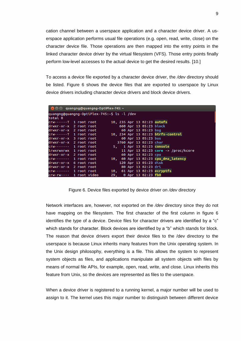
To access a device file exported by a character device driver, the /dev directory should
be listed. Figure 6 shows the device files that are exported to userspace by Linux
device drivers including character device drivers and block device drivers.
Figure 6. Device files exported by device driver on /dev directory
Network interfaces are, however, not exported on the /dev directory since they do not
have mapping on the filesystem. The first character of the first column in figure 6
identifies the type of a device. Device files for character drivers are identified by a “c”
which stands for character. Block devices are identified by a “b” which stands for block.
The reason that device drivers export their device files to the /dev directory to the
userspace is because Linux inherits many features from the Unix operating system. In
the Unix design philosophy, everything is a file. This allows the system to represent
system objects as files, and applications manipulate all system objects with files by
means of normal file APIs, for example, open, read, write, and close. Linux inherits this
feature from Unix, so the devices are represented as files to the userspace.
When a device driver is registered to a running kernel, a major number will be used to
assign to it. The kernel uses this major number to distinguish between different device

10
drivers, not by the names of the device drivers, however. A device driver may have
many instances, and minor numbers are used by the kernel assign to these device
driver instances. As can be seen from figure 6, the fifth column indicates the major
number of a device driver, and the sixth row indicates the minor number. We can have
the same major number but cannot have the same minor number.
Since the GPIO device driver is a character device driver, it must therefore implement
and register entry points or methods that enable userspace applications to manipulate
the device as a file. These entry points are described in the struct file_operations struc-
ture which is defined in <linux/fs.h> header file in Linux. Some of the most important
entry points for a character device driver are shown in listing 1 below.
Listing 1. Entry points for the GPIO device driver
Implementing the entry points and registering them is not sufficient when writing a
character device driver. Several other steps have to been taken, and they can be gen-
eralized from two perspectives: code-flow perspective and data-flow perspective. From
the perspective of code-flow, character device drivers possess an initialization function,
called raspi_gpio_init() in this project, that takes care of initializing the character device
driver and registering the device driver to the kernel by using registration functions (e.g.
cdev_add). The next is a collection of methods such as the ones mentioned in listing 1
which directly map to system calls. The last is bottom halves, timer handlers, interrupt
service routines and other support infrastructure. From a data-flow perspective, charac-
ter device drivers have at first a driver-specific data structure to keep track of the state
of the device driver itself. Secondly, it has a struct cdev structure. The Linux kernel
uses this structure as an abstraction for character device drivers, and this is often nest-

11
ed inside the driver-specific data structure. Thirdly, it has a struct file_opentations struc-
ture which has already been mentioned in listing 1. The last one is a struct file structure
that holds information about the associated /dev device file. [9,121.] By now, it is be-
lieved that the reader should have a basic knowledge of what constitutes a Linux char-
acter device driver and the relation between userspace applications, device files, sys-
tem calls, entry points and character device drivers. Detailed implementation of the
GPIO character device driver will be discussed in chapter 4.
One important point worth mentioning here is that the subject of interrupt handling in
Linux was studied during the design of the project, and I did not really understand to a
large degree about interrupt handling in Linux. As a result, interrupt handling can be
considered to be an experimental feature in the design of the device driver.
3 Design of the GPIO Device Driver
3.1 Project Setup
The first step in the design of the GPIO device driver in this project was to set up a
proper embedded Linux development environment. Figure 7 shows the development
setup used in the project. On the left-hand side of the figure is a host development sys-
tem which runs on my favorite Ubuntu 12.04 Long Term Support (LTS) Linux distribu-
tion. To the right of the figure is an embedded Linux target which, in this case, is the
Raspberry Pi platform. Communication between the host development system and the
embedded Linux target is done via Ethernet. The platform's Ethernet interface and the
Ethernet hub's socket is connected using an RJ45 Unshielded twisted pair (UTP) ca-
ble. Similarly, the host development system's Ethernet interface is connected to the
Ethernet hub's socket using an RJ45 UTP cable. The serial connection RS-232 was
not used in the project since host-target communication was done using Secure Shell
(SSH) protocol. In order to use the SSH protocol as a means of communication be-
tween the host and the target, an SSH daemon was installed in Raspberry Pi, which
makes the target become a server, whereas an SSH client was installed in the host
development system, thus making the host a client.

12
Figure 7. Project development setup
Reprinted from Hallinan (2010) [6,14]
After the target has been booted successfully, it will receive a dynamic Internet Proto-
col (IP) address. This IP address is assigned dynamically from the Dynamic Host Con-
figuration Protocol (DHCP) server. Given the Media Access Control (MAC) address of
the target, the dynamic IP address assigned to the target can be found by using the
following command from the host:
$ arp -a
This command lists MAC and IP addresses of all the devices available on a Local Area
Network (LAN). By doing so, the assigned IP address is found and the host can make a
connection to the target by using the SSH protocol. At the initial stage of the design, it
was realized that it is time-consuming and not convenient to find out the dynamic IP
address assigned to the target after each time the target is rebooted. The solution to
solve this inconvenience was to install a Domain Name System (DNS) client on Rasp-
berry Pi and to sign up a domain name from a DNS hosting website. In this project, a
DNS client called ddclient was installed on Raspberry Pi and a domain name was reg-
istered from a free DNS hosting website from the link http://freedns.afraid.org. For se-
curity reasons, in this thesis report a domain name called vunguyen.fyp.org and a user
name “pi” will be used when referring to the actual domain name that was registered
from the DNS hosting website mentioned just before and the user name from the tar-
get, respectively. After all the networking had been set up properly, communication
13
between the host and the target was tested. Apparently, the procedure became much
simpler and faster by simply using the following command from the host:
$ ssh [email protected]
A password required by the ssh server which is the target was entered for checking
authentication. After that, the host could interact with the target board as if it was work-
ing on the local host machine. Further information about the development environment
setup can be referenced from my personal blog page at http://e-linux-note.blogspot.fi/.
The physical setup of the development environment has been covered by now. The
following paragraphs will discuss the software aspects the host development system
needed in the project.
Regarding a programming tool, an Eclipse Indigo version 3.7.2 Integrated Development
Environment (IDE) was chosen to be installed in the development host. The Eclipse
IDE is an open source programming tool which has a base workspace and a plug-in
system for customizing the programming environment. Eclipse was chosen as a pro-
gramming tool because it offers a C/C++ Development Tools plug-in which supports
programming in the C language. What's more, it contains many nice features such as
syntax highlighting, on-the-fly syntax check, auto-completion, code folding, code navi-
gation, and so on. These features can help speed up the coding process, thus reducing
the project time allocated for the implementation phase. In order to develop application
programs and Linux device drivers, the Eclipse IDE alone is not sufficient. Since the
target platform runs on the ARM1176JZF-S processor, a toolchain was needed to
cross-compile the source code so that it could run on the target. It should be noted that
the native GNU C Compiler (GCC) compiler on the host is targeted to build source
code for Intel x86 family processors, not for other processor architectures. The tool-
chain used in the project was gcc-linaro-arm-linux-gnueabihf-raspbian. This toolchain
was downloaded from the link https://github.com/raspberrypi/tools. The last software
component needed in the development host was the source code for the Linux kernel.
It was obtained from the Raspberry Pi kernel source code repository at
https://github.com/raspberrypi/linux. To ease the management of the toolchain, the
Linux kernel source code, application programs, Linux device drivers, final report, and
other project related documents, I proceeded to set up the layout for a project work-
space. The process of organizing the layout could be compared to making the layout
for the thesis report which is being worked on now. At the top of the project workspace
14
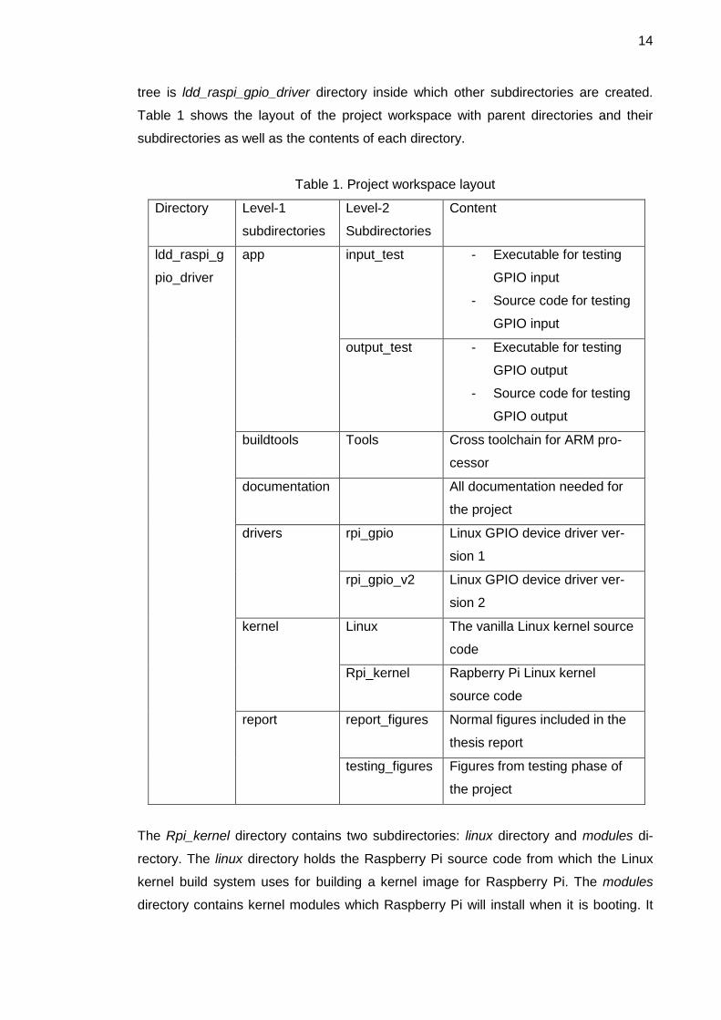
tree is ldd_raspi_gpio_driver directory inside which other subdirectories are created.
Table 1 shows the layout of the project workspace with parent directories and their
subdirectories as well as the contents of each directory.
Table 1. Project workspace layout
Directory Level-1
subdirectories
Level-2
Subdirectories
Content
ldd_raspi_g
pio_driver
app input_test - Executable for testing
GPIO input
- Source code for testing
GPIO input
output_test - Executable for testing
GPIO output
- Source code for testing
GPIO output
buildtools Tools Cross toolchain for ARM pro-
cessor
documentation All documentation needed for
the project
drivers rpi_gpio Linux GPIO device driver ver-
sion 1
rpi_gpio_v2 Linux GPIO device driver ver-
sion 2
kernel Linux The vanilla Linux kernel source
code
Rpi_kernel Rapberry Pi Linux kernel
source code
report report_figures Normal figures included in the
thesis report
testing_figures Figures from testing phase of
the project
The Rpi_kernel directory contains two subdirectories: linux directory and modules di-
rectory. The linux directory holds the Raspberry Pi source code from which the Linux
kernel build system uses for building a kernel image for Raspberry Pi. The modules
directory contains kernel modules which Raspberry Pi will install when it is booting. It

15
is, undoubtedly, impossible to compile a Linux device driver without a Makefile file.
Therefore, inside the rpi_gpio and rpi_gpio_v2 subdirectories are Makefile files used by
the Eclipse IDE during Linux device driver compilation process. The Makefile file is
shown in listing 2.
Listing 2. Makefile file for Linux device driver compilation
Finally, a note about the vanilla Linux kernel. This is an official Linux kernel which is
hosted at the main Linux kernel website https://www.kernel.org/. This kernel is located
in the kernel level-1 subdirectory for future experiments when the project has been
completed.

16
3.2 Design of Per-device Structure and Initialization and Exit Routines
Since the per-device structure (driver-specific data structure) is the information reposi-
tory which the GPIO character device driver instantiates and revolves, it was designed
first. The structure consists of the following data elements:
A cdev kernel abstraction element for character device drivers
An instance of struct gpio structure describing a GPIO pin with configuration
A variable indicating the state of a GPIO pin (low or high)
A variable indicating the direction of a GPIO pin (input or output)
A boolean variable used to enable or disable interrupt on a GPIO pin
A flag indicating rising or falling edge trigger on a GPIO pin
A counter for keeping track of the number of requests for interrupt
A spinlock used for synchronization.
The per-device data structure plays the role of representing a GPIO pin on the Rasp-
berry Pi platform. There are, in total, 21 GPIO pins on Raspberry Pi; therefore, 21 in-
stances of the per-device data structure were created to represent these GPIO pins.
After the per-device structure had been created, the design of driver initialization rou-
tine and driver exit routine took place. The driver initialization routine is the one which is
called first when the kernel installs the GPIO device driver. The driver exit routine, in
contrast, is the last one called by the kernel when being unloaded from the system. In
this thesis report, device driver and kernel module will be used interchangeably. Be-
cause the driver initialization routine is the bedrock for registering the GPIO character
device driver to the kernel, it will be responsible for doing the following steps:
Register a range of character device numbers
Create a device class in /sys directory
Claim GPIO pin resources
Allocate memory for the per-device structure
Initialize a spinlock to be used for synchronization
Register character device to the kernel
Create device nodes to expose GPIO resources to userspace
Get current timestamp used for contact debouncing.

17
A feature in the design of the GPIO character device driver was to let a userspace poli-
cy daemon udevd to dynamically create device nodes in the /dev directory. That is why
step 2 and step 7 were added to the initialization routine. It should be kept in mind that
the implementation of the GPIO device driver followed the steps of driver initialization in
the order mentioned above. Handling errors was the responsibility in the implementa-
tion phase. As a rule, if there is an error when calling kernel APIs, it must log error in-
formation to the kernel log system, release any previously allocated resources, and exit
without any further processing. Doing the opposite of what the driver initialization rou-
tine is supposed to do is the driver exit routine. When the system is rebooted or when a
userspace user issues a command, for example rmmod, the exit routine takes action.
Firstly, it unregisters a range of character device numbers. After that, it frees all the
per-device structures allocated previously during the initialization routine. Next, it re-
leases all the device nodes in the /dev directory, frees all GPIO pin resources, and sets
the direction of all the GPIO pins to output and sets their logic levels low. Finally, it de-
stroys the device class registered in the virtual filesystem mounted at /sys directory. It
is a good practice to set the direction of all GPIO pins to output and their logic levels
low. This is because sometimes a user of the GPIO device driver might make mistakes
by accidentally short-circuiting a certain GPIO pin, thus playing havoc with the proces-
sor of Raspberry Pi. It cannot prevent Raspberry Pi from damaging when a user ap-
plies a high voltage to a GPIO pin, however.
3.3 Design of the Entry Points for the GPIO Device Driver
The GPIO character device driver consists of four entry points which handle requests
from userspace applications on behalf of system calls. The open entry point went first
when designing entry points of the GPIO character device driver. This order of design
was followed based on the theory of code-flow perspective discussed in section 2.4.
Although the open entry point is the first operation exercised on the device file, this is
not compulsory for a character device driver to declare. Opening a device file always
returns success even if this entry point is NULL. [11,51.] The open entry point was de-
signed for the device driver, however. The reason for this is that it is needed for regis-
tering interrupt resources and keeping track of how many times an interrupt is request-
ed by userspace applications. Moreover, it is recommended that an interrupt request
be called when a device file is first open [11,261]. Clearly, this means that a request for
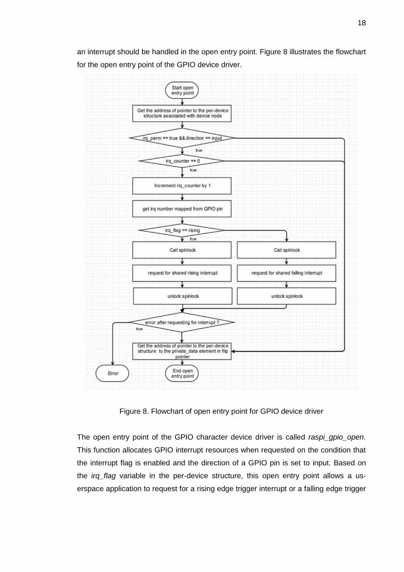
18
an interrupt should be handled in the open entry point. Figure 8 illustrates the flowchart
for the open entry point of the GPIO device driver.
Figure 8. Flowchart of open entry point for GPIO device driver
The open entry point of the GPIO character device driver is called raspi_gpio_open.
This function allocates GPIO interrupt resources when requested on the condition that
the interrupt flag is enabled and the direction of a GPIO pin is set to input. Based on
the irq_flag variable in the per-device structure, this open entry point allows a us-
erspace application to request for a rising edge trigger interrupt or a falling edge trigger

19
interrupt. The last feature which was designed for the raspi_gpio_open entry point was
that an interrupt line could be shared by multiple userspace applications.
When a userspace application closes a device file, the kernel invokes the release entry
point. Like the open entry point, the release entry point is not needed and can be
NULL. For the GPIO device driver, the release entry point was designed. The design of
this release entry point followed after the design of the open entry point. The release
entry point, when being called, is responsible for releasing the GPIO interrupt resource
that has been requested before. It only releases the interrupt resource when the device
is last closed. To do this, there is a counter called irq_counter inside the per-device
structure which keeps track of how many times an interrupt has been requested. The
design philosophy of the GPIO character device driver was defined so that multiple
userspace applications could share the same interrupt resource on a certain GPIO pin.
In addition to that feature, the release entry point also controls enabling and disabling
of an interrupt upon request regardless of how many devices are using the interrupt. A
spinlock used for synchronization is also part of the code-flow in the release entry
point. The last two entry points for the GPIO character device driver are read entry
point and write entry point.
Perhaps, the read entry point was the easiest part during the design phase of the de-
vice driver. This entry point is called, by design, raspi_gpio_read. This function allows
userspace applications to read the logic state of input GPIO pins and of output GPIO
pins. Since multiple processes are allowed to read the logic state of a GPIO pin simul-
taneously, it was not designed to use a spinlock for protecting atomic sections of code
or synchronization or whatsoever.
The last and also the most important entry point is the write entry point. This entry point
is responsible for exchanging data between userspace and a hardware device. The
write entry point does the opposite to the read entry point. Instead of reading from the
hardware device, it receives bytes of data from the userspace and then writes what has
been received directly to the device. Finally it returns the number of bytes that it has
successfully written. That is the mechanism how the write entry point works. For the
GPIO character device driver, the write entry point accepts a set of defined commands
received from the userspace and takes action accordingly. In particular, it was de-
signed to accept a set of seven defined commands from userspace. The commands

20
are, in fact, a string of characters sent to the device file by a userspace application.
Those commands are listed in table 2.
The description in table 2 should be descriptive enough to understand what a com-
mand asks the write entry point to perform. If a userspace application needs to set, for
example, GPIO pin 2 to output and set it to logic level low, it will need to do the follow-
ing commands based on the description from table 2.
$ echo out > /dev/raspiGpio2
$ echo 1 > /dev/raspiGpio2
Table 2. Command set for GPIO character device driver
Command Description
“out” Set GPIO direction to output
“in” Set GPIO direction to input
“1” Set GPIO pin's logic level to high
“0” Set GPIO pin's logic level to low
“rising” Enable rising edge trigger
“falling” Enable falling edge trigger
“disable-irq” Disable interrupt on a GPIO pin
After that the GPIO pin 2 will be set to output with high logic level. What the first
command does is that it first opened the device file /dev/raspiGpio2 and sent to the
device file the string “out”. The string “out” or command “out” in this case was then read
by the write entry point. It then processed if a correct command was received. If so, it
sets the direction of GPIO pin 2 to output. Otherwise, error will be printed on the
console. In the demonstration above, there was no error reported. Therefore, it means
that the command “out” was processed successfully by the write entry point, and the
direction of GPIO pin 2 was set to output. The same process happens when the
command “1” was written to the /dev/raspiGpio2 device file. Again, there was no error
and it was measured from the GPIO pin 2 by a Digial Multimeter (DMM) that the
voltage of the pin was about 3.287 V. It is easy to use from the userspace application's
point of view. However, there are many low-level details that require the job of the
GPIO device driver’s write entry point.
21
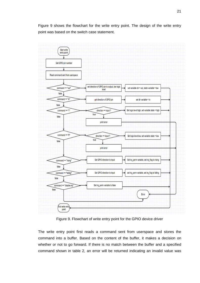
Figure 9 shows the flowchart for the write entry point. The design of the write entry
point was based on the switch case statement.
Figure 9. Flowchart of write entry point for the GPIO device driver
The write entry point first reads a command sent from userspace and stores the
command into a buffer. Based on the content of the buffer, it makes a decision on
whether or not to go forward. If there is no match between the buffer and a specified
command shown in table 2, an error will be returned indicating an invalid value was
22
received. When a request for an interrupt such as falling or rising is received, it will be
processed by the write entry point as a high priority task, thus overriding the setting of
the GPIO pin’s direction and the permission flag in the per-device structure. Other
commands are just trivial commands for setting the direction and logic level of a GPIO
pin. For sections of code which require to be atomic, the implementation for the write
operation entry point should be able to decide suitable places for inserting a spinlock.
3.4 Design of Interrupt Handling Functions
Interrupt handling is a feature that was decided to be added to the GPIO device driver
later when the first version of the driver had been finished. This was due to some
changes in the requirements of the project. The subject of interrupt handling was stud-
ied during the design phase, and was not really understood thoroughly. For that rea-
son, this feature was designed in the second version of the GPIO device driver, and is
considered to be experimental. To make this feature useful for userspace applications,
more work needs to be done.
Requesting for interrupt resources and releasing them were already mentioned in sec-
tion 3.2. This section will look at the design of an interrupt handler that is called by the
kernel when a hardware interrupt signal arrives. In addition, a simple timing function
was designed so that it solves a problem known as contact bouncing. Contact bounc-
ing is the problem which is caused by mechanical switches when they are pressed and
released. This problem causes the processor to misinterpret when the signal from the
switch oscillates several times, going from logic level low to high and vice versa. In
other words, when a switch is pressed and released only one time, it will be interpreted
by the processor as several switch presses.
Basically, when called by the kernel, the interrupt handler starts taking a timestamp
right at the moment it was started. It will then compare the current time with the last
timestamp when it was called. If the time duration between successive calls is less than
200 milliseconds, it will consider the interrupt signal that has just arrived as a signal
pulse caused by contact bouncing. Otherwise, it will be interpreted as an interrupt sig-
nal; the handler takes proper actions that userspace applications desire. In the GPIO
device driver, the interrupt handler simply displays some information to the kernel log-
ging system to signify that an interrupt signal has been received. In order to avoid be-
ing interrupted by another interrupt signal when the interrupt handler is busy, functions

23
local_irq_save and local_irq_restore were used to disable interrupt signals temporarily
and then resume them as before.
The timing function was designed in quite a simple way. This function is named millis
which means milliseconds. It takes no argument and returns the current system time in
milliseconds. The data type of the return value was designed to be unsigned int. It
takes the current system time by calling do_gettimeofday(struct timeval *tv) function
which is defined in <linux/time.h> header file.
4 Implementation of the GPIO Device Driver
4.1 Linux Kernel Compilation and Installation
In order to see how the Linux kernel was compiled and installed for Raspberry Pi in this
project, it is necessary to understand how Raspberry Pi boots up. The Broadcom
BCM2385 SoC consists of two processors; one is a VideoCore IV GPU and the other is
an ARM1176JZF-S 700 MHz core which runs the Linux kernel. A small RISC core on
the GPU starts running first at power-up, and this core runs the first stage bootloader
which has been preprogrammed into the SoC to mount the FAT32 boot partition on the
SD card. Next the GPU looks for the second stage bootloader called bootcode.bin and
loads it into the system memory and starts executing that code. Then the second stage
bootloader searches for a file called config.txt from the SD card and searches again for
the kernel.img file which is the Linux kernel image. Finally, the kernel image is loaded
into memory at the address (0X8000), and this in turn starts the ARM processor exe-
cuting at that memory location. The GPU is ready and the ARM will start using the code
in kernel.img. [12.]
In a nutshell, the following components are needed for booting the Raspberry Pi plat-
form:
A second stage bootloader file called bootcode.bin
A config.txt file used for kernel settings
A kernel.img file
24
Linux kernel modules
Other files: start.elf, fixup.dat, .config configuration file.
The bootcode.bin second stage bootloader, the start.elf and fixup.dat files were down-
loaded for the project from the Raspberry Pi main repository at
https://github.com/raspberrypi/firmware/tree/master/boot
The config.txt file already exists in the running Raspberry Pi platform at /boot directory.
So, it was copied from there. If that file is not available, it can be downloaded from
https://github.com/Evilpaul/RPi-config/blob/master/config.txt
The kernel.img kernel image and the Linux kernel modules were cross-compiled from
the development host. All of the preparation steps were done as follows:
Get the Raspberry Pi Linux kernel source code
Get a gcc-linaro-arm-linux-gnueabihf-raspbian toolchain for cross compilation
Get an existing .config configuration file.
The first step in compiling the kernel image for Raspberry Pi was to have the Raspber-
ry Pi Linux kernel source code. It was obtained from
https://github.com/raspberrypi/linux.git by using the following git command:
git clone https://github.com/raspberrypi/linux.git
The kernel source code was then stored in the Rpi_kernel workspace directory as
shown in table 1. The next step was to get a toolchain in order to cross-compile for the
target. The toolchain is stored in the tools level-2 subdirectory in the workspace. It was
downloaded by using the following command:
git clone https://github.com/raspberrypi/tools
The Raspberry Pi tools directory contains several toolchain versions. gcc-linaro-arm-
linux-gnueabihf-raspbian was chosen since it contains linaro patches. The last one
needed was a configuration file for kernel compilation. In order save time, an existing
configuration file from a running Raspberry Pi system was retrieved. This configuration
file is stored in /proc/config.gz directory. This file was copied, unzipped, renamed to
.config and saved into the top tree of the Raspberry Pi kernel. Next the compilation

25
process took place. The following commands were run to compile the Linux kernel im-
age. It should be noted that they were executed in the following order:
make oldconfig ARCH=arm CROSS_COMPILE=${CCPREFIX}
make ARCH=arm CROSS_COMPILE=${CCPREFIX}
make modules_install ARCH=arm CROSS_COMPILE=${CCPREFIX}
The result after a successful compilation was a kernel image and a folder containing
kernel modules. The new kernel image was stored in the /linux/arch/arm/boot/ directory
of the kernel source tree. It was a compressed file called zImage, so it was uncom-
pressed to be used on Raspberry Pi. The tool for uncompressing zImage kernel image
comes from the tools/mkimage directory in the workspace. This tool is called image-
tool-uncompressed.py which is a kind of Python script. The following commands were
used to uncompress and upload the zImage kernel image to Raspberry Pi:
./imagetool-uncompressed.py zImage
scp kernel.img [email protected]:/tmp
Another component needed for booting the Raspberry Pi platform is kernel modules.
These modules were stored in my development host's directory at the path
/home/quangng/study/linux_device_drivers/Metropolia/labs/project/ldd_raspi_gpio_driv
er/kernel/Rpi_kernel/modules. Since this directory contains quite a large number of
modules, it was compressed before uploading to Raspberry Pi to save uploading time.
It was done as follows:
cd ./Rpi_kernel/module
tar czf modules.tgz *
scp modules.tgz [email protected]:/tmp
Finally, the kernel image and the kernel modules were installed for Raspberry Pi using
the command as follows:
cd /
sudo mv /tmp/kernel.img /boot/
sudo tar xzf /tmp/modules.tgz
rm /tmp/modules.tgz

26
After Raspberry Pi were rebooted and connected to the development host over SSH,
the command uname -r was used to verify that the new kernel image that had been
built before was booted successfully.
Figure 10. Successful result after building a new Linux kernel
Figure 10 shows the result from a successful boot from Raspberry Pi with the new ker-
nel version 3.10.34+. After the successful compilation of the new kernel, the target was
ready for the implementation and testing later on during the project.
4.2 Implementation of Per-device Structure and Initialization and Exit Routines
The design of the per-device structure, the initialization routine and the exit routine was
discussed in section 3.2. This section gives more details on how each of them was
implemented by analyzing their source code. Listing 3 shows a snippet of code that
was implemented for the per-device data structure.
Listing 3. Per-device data structure for the GPIO device driver
The very first pieces of code implemented for the GPIO device driver were the per-
device data structure. This data structure is named raspi_gpio_dev. In the project,
27
almost every name of variables, structures, and functions were named beginning with
the prefix raspi_gpio_. Each instance of the per-device data structure represents a
GPIO pin. The first element of the structure is an instance of struct cdev structure. This
is the internal structure of the Linux kernel that represents character devices. This
structure is defined in <linux/cdev.h> header file. The next element is an instance of
struct gpio structure. As the name implies, this element is used to store such
information as GPIO pin number, flags to define the status of a GPIO pin when it is first
claimed, and a pointer to the const char data type called label. The struct gpio structure
encapsulates all the three fields just mentioned; hence, when using this structure to
represent a GPIO pin, it will be much easier to handle. The next two elements in the
per-device structure are state and dir elements which are of user-defined data types.
The user-defined data type for the state data element has two values: low or high.
Likewise, the data type of dir data element has two discrete values: in or out. To
support the interrupt feature, three more data elements were added to the
raspi_gpio_dev structure. They are irq_perm, irq_flag, and irq_counter. The irq_perm is
of bool data type, so it has two values, either true or false. The irq_flag is of data type
unsigned long which is used to determine the triggering type for an interrupt. The
irq_counter is of data type unsigned int which keeps track of the number of requests for
interrupt from userspace applications. The last element is a lock that is of system data
type spinlock_t. This data element is used for synchronization purposes.
When the GPIO kernel module is loaded by the kernel upon request, the initialization
routine will be called. First of all, raspi_gpio_init () invokes alloc_chrdev_region() to
dynamically request a range of unused character device numbers. Variable first of data
type dev_t contains the allocated major number if the call is successful. The second
and third arguments passed into alloc_chrdev_region() require the function to allocate
NUM_GPIO_PINS number of minor devices starting from zero. The last argument is
the device name which will appear in /proc/devices when the device driver is registered
successfully. This argument is defined using a macro called DEVICE_NAME. Figure 11
shows the output from cat /proc/devices command.
When the Raspberry Pi GPIO kernel module has been registered successfully, display-
ing the content of /proc/devices directory shows the major number allotted for the de-
vice which, as shown in figure 11, is 248 in the first column. After that, the initialization
routine creates a class under the virtual filesystem which is mounted at /sys by using
function class_create(). Together with function class_create(), the function de-

28
vice_create() results in the generation of 21 uevents. Since there are, in total, 21 GPIO
pins on Raspberry Pi, the raspi_gpio_init() loops 21 times. With each iteration, it re-
quests the kernel to allocate memory dynamically for the per-device structure using
kernel API function kmalloc(). It should be noted that the cdev is embedded inside each
per-device structure. When the kernel allocates memory for the per-device structure,
cdev will also be allocated. If successful, the initialization routine will continue by claim-
ing resource for a GPIO pin with initial status of a GPIO pin set to output and low logic
level. Since initial values and states should be set at the beginning when the kernel
module is first loaded, the initialization routine is responsible for doing that. In particu-
lar, it sets the direction of all GPIO pins to output and initial states of GPIO pins to low
level, disables the irq_perm flag in each per-device structure, sets the irq_flag flag to
rising edge triggering, initializes the irq_counter to be zero since there is no interrupt
request at the beginning, and finally sets the owner of the module to THIS_MODULE.
In order to protect atomic sections of code, a spinlock is used. Hence, it is initialized for
each per-device structure. Finally, cdev_init() associates the file operations in
raspi_gpio_fops structure with the cdev. It is also responsible for connecting major and
minor numbers previously allocated to the cdev. If everything goes smoothly without
any error, the initialization process completes and prints out a message "RaspberryPi
GPIO driver initialized" indicating its happiness.
Figure 11. Output shown from cat /proc/devices command
Listing 4 shows the implementation of the exit routine. When a kernel module is being
unloaded from the system, the kernel calls this function to take care of that job. The exit

29
function of the GPIO device driver is called raspi_gpio_exit(). Basically, its job is to de-
allocate resources that were requested from the initialization routine. Firstly, it unregis-
ters from the system a range of NUM_GPIO_PINS device numbers. To be specific, the
value of NUM_GPIO_PINS is defined to be 21. There are 21 per-device structures rep-
resenting each GPIO pin. These structures were allocated dynamically by the kernel. In
order to de-allocate those, the kernel API function kfree() is used.
Listing 4. Implementation of exit routine
As explained in section 3.2, the exit routine should set the direction of all GPIO pins to
output and their logic levels to low. For that reason, gpio_direction_output() is called.
This function is defined in <linux/gpio.h> Linux header file. The resource for GPIO pins
were requested by gpio_request_one() before, so gpio_free() will take care of releasing
those resources. Finally, all the information that populates the virtual filesystem mount-
ed at /sys directory and all the uevents created by device_create() are destroyed by
class_destroy() and device_destroy(), respectively.

30
4.3 Implementation of the Entry Points for the GPIO Device Driver
When a user space application opens a corresponding device file, the
raspi_gpio_open() entry point will be invoked by the kernel. Listing 5 shows the imple-
mentation of the raspi_gpio_open() entry point.
Listing 5. Implementation of raspi_gpio_open entry point
The implementation of the open entry point was first started by obtaining a minor
number that corresponds to a GPIO pin number. Mapping between a minor number
and a GPIO pin number was specified by design. The inode which is passed as an
argument to raspi_gpio_open() holds the address of the cdev structure allocated during

31
initialization. Since struct cdev structure is nested inside the raspi_gpio_dev per-device
structure as show in listing 3, the raspi_gpio_dev structure is the container of the struct
cdev structure. In order to access data elements of the per-device structure, the
address of it needs to be elicited. The open entry point uses the kernel helper function
container_of() to do this. The address of raspi_gpio_dev structure is needed not only in
the open entry point but also in other entry points including release, read, and write.
Hence, this address is assigned to the private_data data field that is part of the struct
file structure, the second argument. The raspi_gpio_open() entry point is also
responsible for requesting interrupt resources upon request from userspace
applications. The open entry point which was implemented based on the flowchart
shown in figure 8 checks the status of the interrupt request permission variable
irq_perm and the GPIO pin direction variable dir. If the interrupt permission variable
irq_perm is set and the direction of the GPIO pin is set as input, the entry point will
continue by checking the value of irq_counter. Otherwise, it will return zero indicating
everything is fine. The irq_counter is used to keep track of how many times an interrupt
is requested. If the value of the irq_counter is equal to zero, it means that an interrupt
resource has not been acquired. As a result, the entry point will request for an interrupt
resource from the GPIO pin and increment the value of the irq_counter by one. Since
requesting for an interrupt resource must be atomic, spin_lock_irqsave() and
spin_unlock_irqrestore() are used to protect this section of code. If requesting for an
interrupt is successful, the open entry point will return zero. If there is an error due to
interrupt request, the entry point will log the string "unable to claim irq: %d, error %d\n"
to the kernel logging system and exit with an error code. Next the release entry point
was implemented.
When a device file is closed by a userspace application, the kernel invokes the release
entry point. The release entry point for the Raspberry Pi GPIO device driver is called
raspio_gpio_release. Two arguments are passed into the raspi_gpio_release entry
point, namely inode and filp. The entry point does not make use of the filp pointer; only
the inode is used to get the address of the per-device structure. It can, of course, elicit
the per-device structure's address from the private_data filed inside the struct file struc-
ture as an alternative. A GPIO pin number is obtained by using the inline function imi-
nor(). This number is needed when the release entry point de-allocates an interrupt
resource from a GPIO pin. There are two cases in which the release entry point is sup-
posed handle. The first case is when an interrupt is enabled. In such a case, the re-
lease entry point keeps track of the value of the irq_counter. When the device is last

32
closed, the value of the irq_counter should be zero after being decremented and the
interrupt will be released by the entry point. On the other hand, if the interrupt is still
enabled and the value of the irq_counter is not equal to zero after being decremented,
this means that some userspace applications are still using the interrupt, and therefore,
the release entry point will just return zero indicating the device file is closed success-
fully. The second case is when interrupt is asked to be disabled. The release entry
point will respond to the request by checking the value of the irq_counter. If this value
is equal to zero, it means that the interrupt resource has already been released, thus
no need to do anything else. If the irq_counter value is larger than zero, some us-
erspace applications are still using the interrupt. Since the interrupt is asked to be disa-
bled, the release entry point will force the irq_counter value to be zero and then release
interrupt resource. Accessing the irq_counter and releasing the interrupt resource
should be atomic. As a result, the spinlock is utilized to protect these critical sections of
code.
Listing 6. Implementation of raspi_gpio_read entry point
The last two entry points for the GPIO device driver are raspi_gpio_read entry point
and raspi_gpio_write entry point. Listing 6 shows the implementation of the
raspi_gpio_read entry point. This entry point was the easiest and simplest part of the
device driver implementation, so it will be explained briefly. The raspi_gpio_read entry
point first obtains a GPIO pin number from a device file by using the inline function imi-
nor(). After that it gets the state of the GPIO pin with the help of the kernel function
33
gpio_get_value(). This function returns either zero or one. Then the value returned from
gpio_get_value() function will be converted into a character and saved to a temporary
variable called byte. Finally this value will be copied to the userspace by using the ker-
nel API function put_user(). It should be noted that copying from kernel space to us-
erspace cannot be done by using normal C library functions. Instead, this has to be
done by using kernel API functions such as put_user() or copy_to_user() functions.
Upon completion of copying, the raspi_gpio_read entry point exits and returns the
number of bytes copied to the userspace buffer pointed to by the buf pointer, the sec-
ond argument passed into the raspi_gpio_read() entry point.
Similarly, the write entry point performs the task of copying data between a kernel
space and a userspace. The last implementation of entry points for the GPIO device
driver was the raspi_gpio_write() entry point. The struct file structure is passed as an
argument into the raspi_gpio_write entry point. The private_data field contained in this
struct file structure holds the address of the per-device structure which will be needed
in this entry point. This is due to the fact that the address of the per-device structure
was assigned to the private_data filed when the raspi_gpio_open entry point was
called. This assignment can be seen from the third to last line in listing 5. Passed as
the third argument to the write entry point is a count which indicates the number of
bytes a userspace application has written into the buffer which is pointed to by the buf
pointer, the second argument. Based on this information, the raspi_gpio_open entry
point then reads count numbers of bytes from the buffer pointer to by buf pointer into its
own temporary buffer in the kernel space called kbuf. Once the reading process has
been completed and kbuf contains what has been read, the raspi_gpio_open entry
point will compare the value of the kbuf with a set of commands specified in the design
phase. These commands can be referenced from table 2. If the kbuf buffer contains
commands “in” or “out”, the direction of the GPIO pin will be set by using
gpio_direction_in() or gpio_direction_out(), respectively. Besides, the data elements in
the per-device structure will be accessed and updated. For output direction setting, the
data field dir will be set to out, and the data field state will be set to low. The default
logic level when setting output direction is to set it low. For the input direction setting,
only the data field dir needs to be updated and is set to in.
Listing 7 shows a code snippet implemented for the raspi_gpio_write entry point. When
the content of the kbuf buffer is “1” or “0”, it will be understood by the write entry point
that a userspace application requests for setting the logic level of a GPIO pin. The val-
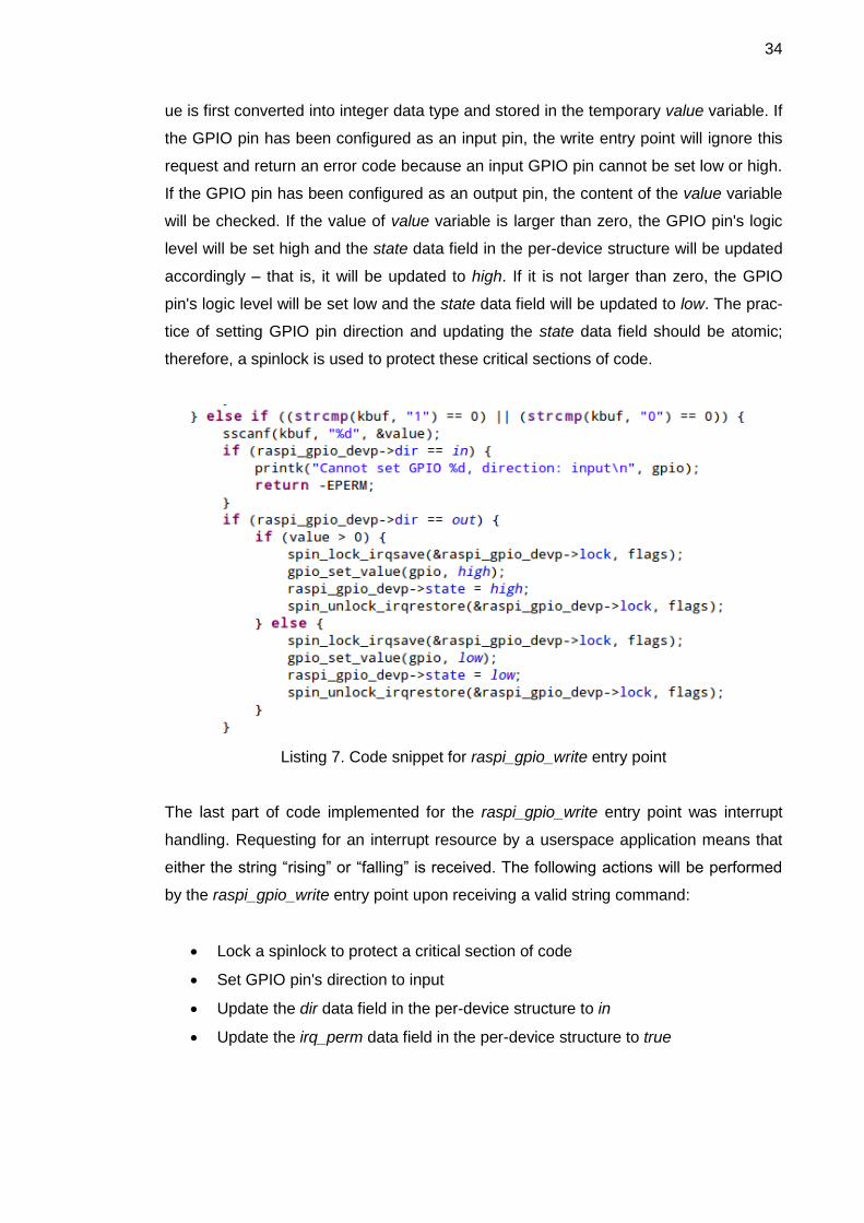
34
ue is first converted into integer data type and stored in the temporary value variable. If
the GPIO pin has been configured as an input pin, the write entry point will ignore this
request and return an error code because an input GPIO pin cannot be set low or high.
If the GPIO pin has been configured as an output pin, the content of the value variable
will be checked. If the value of value variable is larger than zero, the GPIO pin's logic
level will be set high and the state data field in the per-device structure will be updated
accordingly – that is, it will be updated to high. If it is not larger than zero, the GPIO
pin's logic level will be set low and the state data field will be updated to low. The prac-
tice of setting GPIO pin direction and updating the state data field should be atomic;
therefore, a spinlock is used to protect these critical sections of code.
Listing 7. Code snippet for raspi_gpio_write entry point
The last part of code implemented for the raspi_gpio_write entry point was interrupt
handling. Requesting for an interrupt resource by a userspace application means that
either the string “rising” or “falling” is received. The following actions will be performed
by the raspi_gpio_write entry point upon receiving a valid string command:
Lock a spinlock to protect a critical section of code
Set GPIO pin's direction to input
Update the dir data field in the per-device structure to in
Update the irq_perm data field in the per-device structure to true

35
Set irq_flag data field in the per-device structure to IRQF_TRIGGER_RISING if
“rising” command is received
Set irq_flag data field in the per-device structure to IRQF_TRIGGER_FALLING
if “falling” command is received
Unlock a spinlock.
When a userspace application asks to disable interrupt on a GPIO pin, it will send
“disable-irq” command. This command simply means “disable interrupt request” in plain
English. Upon receiving this command, the write entry point will set the irq_perm data
field in the per-device structure to false indicating that the request for interrupt is not
permitted. Any command received by the raspi_gpio_write entry point other than the
ones specified in table 2 will be ignored, and EINVAL error code will be returned. Final-
ly, the entry point will update the current position of the f_pos pointer by count positions
and return the number of bytes received.
4.4 Implementation of Interrupt Handling Functions
The interrupt handling feature in the project was experimental, so the implementation
for it was quite short and simple. Listing 8 shows the source code for interrupt handling
functions. The interrupt handling of the GPIO device driver consists of two functions:
millis() and irq_handler. While millis() is a normal function which returns the current
system time to the caller, the irq_hanlder is a special function which is called only when
a hardware interrupt signal arrives. As for the millis() function, it gets the current system
time by calling the kernel API function do_gettimeofday(). This function returns the cur-
rent system time and stores it in the timeval variable of type struct timeval. After that, it
converts the time stored in timeval variable to milliseconds. What is returned from the
millis() function is the current system time.
Regarding the interrupt handling function irq_handler(), this function will be called when
an interrupt occurs. Due to the nature of interrupt handling, this function was imple-
mented in such a way that it is fast and it does not contain any blocking functions. The
interrupt handler first gets the current time and compares it with the last timestamp
when an interrupt occurred. By trial and error, it was determined that a time duration of
200 milliseconds is good enough to avoid voltage glitches caused by contact bouncing.
The timestamp when the interrupt handler was called is stored in last_interrupt_time

36
global variable as a reference timestamp for the next interrupt. Since an interrupt han-
dler can be interrupted by another interrupt, functions local_irq_save() and lo-
cal_irq_restore() are used to prevent that problem from happening. The irq_handler
interrupt handle is not of practical use since this feature is still experimental. It simply
logs the string “Interrupt [%d] was triggered\n” into the kernel logging system.
Listing 8. Implementation of interrupt handling functions for the GPIO device driver
That was the last part in the implementation of the GPIO character device driver. Chap-
ter 5 will discuss how the device driver was tested.
37
5 Testing of the GPIO Device Driver
5.1 Testing Preparation
Testing was the final phase in the development of the GPIO character device driver for
Raspberry Pi. The purpose of the testing was to verify that the GPIO device driver
worked according to a set of defined test cases. The testing of the device driver was
based on black-box testing. In other words, the functionalities offered by the device
driver were examined case by case. There were three test cases applied to test the
device driver, namely output functionality test case, input functionality test case, and
interrupt functionality test case.
The hardware needed for the testing included 7 white light-emitting diodes (LED), 17
resistors with a resistance of 100Ω, 19 male to female electrical wires, 2 100KΩ resis-
tors, a switch, and 2 breadboards. Each 100Ω resistor was used to limit the current
flowing through each white LED. The switch was used for testing interrupt functionality.
The test software used for testing the GPIO device driver is located at
ldd_raspi_gpio_driver/app directory where ldd_raspi_gpio_driver is the workspace root
directory. Two application programs were developed for testing, and they were written
in the C programming language. The first application program, called output_test.c, is
located at ldd_raspi_gpio_driver/app/output_test and is provided in appendix 2. This
was used for testing output functionality of the device driver. The second application,
called input_test.c, is located at ldd_raspi_gpio_driver/app/input_test and is provided in
appendix 3. This was used for testing input functionality of the device driver. The GPIO
device driver had been loaded into the running kernel before performing each test
case.
5.2 Testing of Output Functionality
The first test case was carried out to verify the output functionality offered by the GPIO
device driver. An application program called output_test was run in the userspace to
test the driver, and it has the following syntax:
./output_test <logic_level>

38
where <logic_level> refers to the logic state that is passed as an argument to the pro-
gram for setting a GPIO pin low or high. If <logic_level> is “1”, the application will set
the logic level of all GPIO pins high, whereas passing “0” as an argument to the appli-
cation program will set all the logic level of all GPIO pins low.
A simple circuit was constructed on a breadboard for testing the output functionality.
Each of the 17 100Ω resistors was connected in series with each of the 17 white LEDs
in order to limit the current flowing through the LEDs. The output from each GPIO pin
was wired to the anode terminal of an LED. The cathode terminal of the LED was con-
nected in series with a 100Ω resistor which in turn was connected to a GND pin from
the breadboard. Below is the output of the application program when invoked from the
command line with arguments ”1” and ”0”, respectively.
Figure 12. Output of the application program output_test with arguments ”0” and ”1”
The results of the output functionality test case are shown in figure 13 and figure 14.
Figure 13 shows that the LEDs connected to the Raspberry Pi P1 header were lit when
the application program was executed with argument “1” being passed into the pro-
gram.
Figure 13. Output functionality testing result with all GPIO pins set high
Figure 14 shows that all the white LEDs went off when the application program was
executed with argument “0” being passed into the program. In fact, four GPIO pins from
39
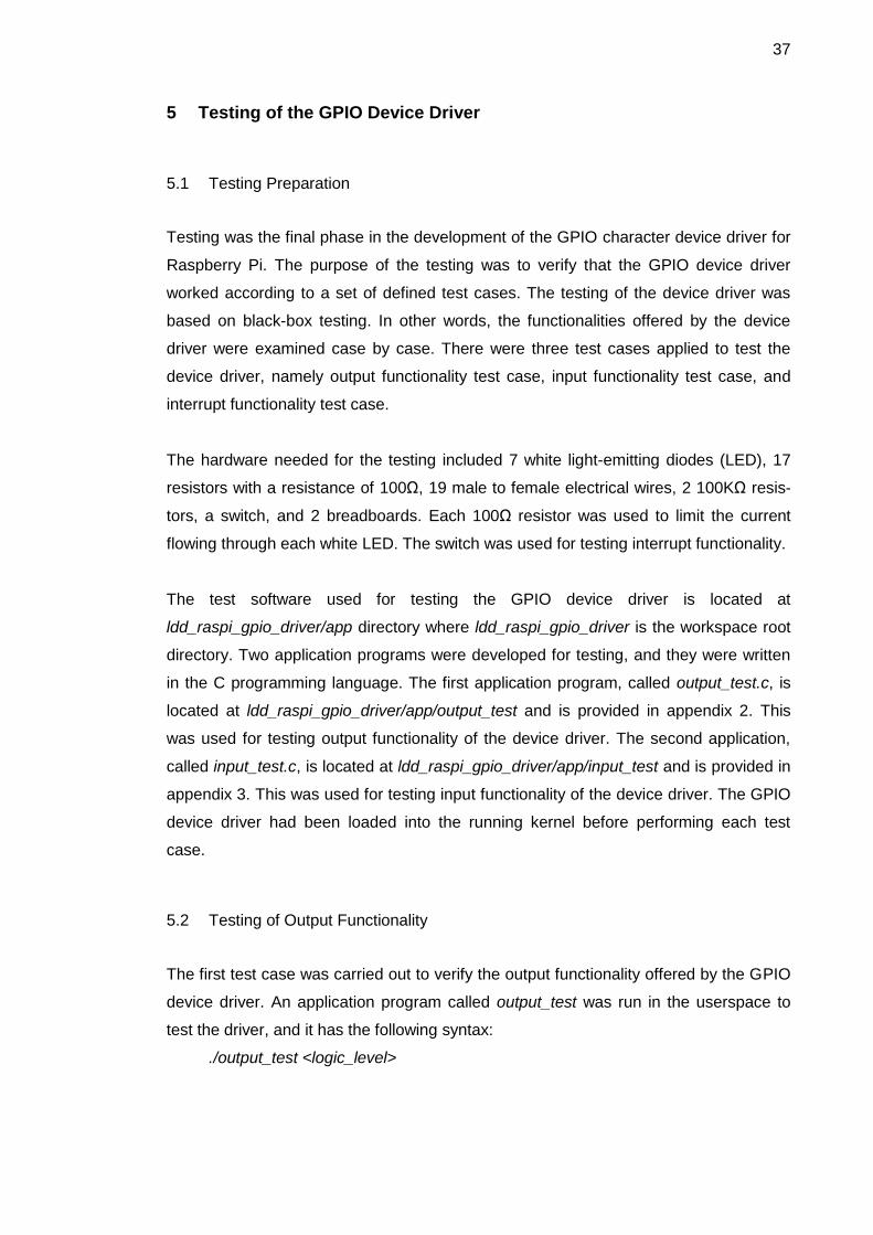
the Raspberry Pi P5 connector were also set high. Because I did not solder any header
into the P5 connector, these four GPIO pins were not tested using LEDs. I did, howev-
er, measure the voltages from each of the four GPIO pins from the P5 connector. The
voltage values were about 3V when GPIO pins were set high, and about 0V with GPIO
pins being set low.
Figure 14. Output functionality testing result with all GPIO pins set low
The next section will show the test setup, testing procedures as well as testing results
from the input functionality test case of the GPIO device driver.
5.3 Testing of Input Functionality
Input functionality test case was performed to verify the input functionality offered by
the GPIO device driver. An application program called input_test was run in the us-
erspace to test the driver. When invoked from the userspace, the application program
first sets all the GPIO pins on Raspberry Pi to input. After that it reads the logic levels
of all the GPIO pins and prints these values to the terminal.
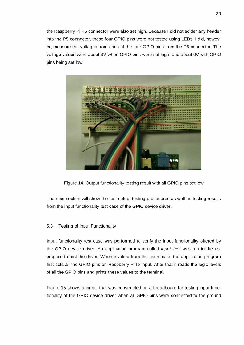
Figure 15 shows a circuit that was constructed on a breadboard for testing input func-
tionality of the GPIO device driver when all GPIO pins were connected to the ground

40
(GND). Each of the 17 GPIO pins was connected in series with one terminal of a 100Ω
resistor. The other end of each resistor was connected to the GND of the breadboard.
Figure 15. Test setup for input functionality testing with GPIO pins connected to ground
In a similar fashion, the circuit in figure 16 was built to test the input functionality of the
device driver. However, in this circuit all the other ends of each resistor were connected
to a 3.3V power supply from the breadboard.
Figure 16. Test setup for input functionality testing with GPIO pins connected to 3.3V
Figure 17 shows the output of the application program input_test when the GPIO pins
were connected to a 3.3 V power supply. All 21 GPIO pins were read by the program
as high logic level except for the last four GPIO pins. This is because these GPIO pins

41
come from the P5 header of Raspberry Pi, and they were left floating. Therefore, their
logic levels are usually low when being set as input.
Figure 17. Input functionality testing result with all GPIO pins connected to 3.3 V
When all GPIO pins were connected to the ground of the breadboard, the application
program was executed again. The logic levels of all GPIO pins were read as “0” as
shown in figure 18.
Figure 18. Input functionality testing result with all GPIO pins connected to GND
The next section will discuss the testing of interrupt handling feature of the device driv-
er. Another circuit was built to interface with a GPIO pin of Raspberry Pi.
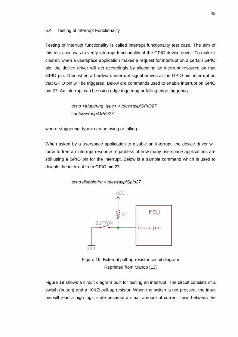
42
5.4 Testing of Interrupt Functionality
Testing of interrupt functionality is called interrupt functionality test case. The aim of
this test case was to verify interrupt functionality of the GPIO device driver. To make it
clearer, when a userspace application makes a request for interrupt on a certain GPIO
pin, the device driver will act accordingly by allocating an interrupt resource on that
GPIO pin. Then when a hardware interrupt signal arrives at the GPIO pin, interrupt on
that GPIO pin will be triggered. Below are commands used to enable interrupt on GPIO
pin 27. An interrupt can be rising edge triggering or falling edge triggering.
echo <triggering_type> > /dev/raspiGPIO27
cat /dev/raspiGPIO27
where <triggering_type> can be rising or falling.
When asked by a userspace application to disable an interrupt, the device driver will
force to free an interrupt resource regardless of how many userspace applications are
still using a GPIO pin for the interrupt. Below is a sample command which is used to
disable the interrupt from GPIO pin 27.
echo disable-irq > /dev/raspiGpio27
Figure 19. External pull-up-resistor circuit diagram
Reprinted from Mando [13]
Figure 19 shows a circuit diagram built for testing an interrupt. The circuit consists of a
switch (button) and a 10KΩ pull-up-resistor. When the switch is not pressed, the input
pin will read a high logic state because a small amount of current flows between the

43
power supply VCC and the input pin. When the switch is pressed, the current will flow
directly to the ground via the 10KΩ resistor. As a result, the input pin reads a low logic
state.
Figure 20. Result of interrupt testing
Figure 20 shows the result of interrupt testing displayed on the kernel log. It was dis-
played by using the following command:
tailf /var/log/messages
Table 3 shows commands issued on the terminal together with actions from the
external circuit and their corresponding results shown in figure 20. Firstly, an interrupt
was requested from the userspace by issuing the command echo rising >
/dev/raspiGpio27. It should be kept in mind that allocating an interrupt resource actually
took place until the device file /dev/raspiGpio27 was opened again. Lines 4 and 5 in
figure 20 show that when the device file /dev/raspiGpio27 was opened by using cat
/dev/raspiGpio27, an interrupted was requested for GPIO pin 27. While reading from
the device file, the switch was pressed four times and the interrupt was triggered as
shown from lines 6 to 10. Line 7 in figure 20 shows that the interrupt was ignored. The
reason for this is that the mechanical switch causes a phenomenon known as contact
bouncing when pressed and released. Contact bouncing is undesirable, and therefore,
it was ignored since the switch was pressed only four times. When the userspace

44
closed the device file, a message “Closing GPIO 27” showed up on line 11 indicating
that the device file was being closed. After that, the interrupt was released as shown on
line 12 because only one userspace process used the GPIO pin 27 for the interrupt at
the time.
Table 3. Commands issued together with actions from external circuit and their corre-
sponding results
Commands issued on terminal and
actions from external circuit
Corresponding result shown in figure 20
echo rising > /dev/raspiGpio27 lines 1 – 3
cat /dev/raspiGpio27
Switch pressed
Lines 4 – 12
echo disable-irq > /dev/raspiGpio27 Lines 13 – 17
cat /dev/raspiGpio27
Switch pressed
Lines 18 – 19
Another interrupt handling feature tested in this test case was to disable the interrupt
on a GPIO pin and to verify if the interrupt was really disabled. Below is the command
used to disable the interrupt on GPIO pin 27.
echo disable-irq > /dev/raspiGpio27
Lines 13 to 17 in figure 20 show the output of the kernel logging system when the de-
vice file /dev/raspiGpio27 was opened to disable the interrupt and closed. To test if the
interrupt on GPIO pin 27 was disabled, the device file was opened again and the switch
was pressed and released several times. No logging messages indicating the interrupt
triggering were displayed on the terminal as shown on lines 18 and line 19 in figure 20.
This means that the interrupt on GPIO pin 27 was successfully disabled.
45
6 Results and Discussion
A complete GPIO character device driver for Raspberry Pi was designed and imple-
mented from scratch. It was also tested in the form of black-box testing during the test-
ing phase of the project. The results of the testing phase show that the device driver
does what it is supposed to function. By and large, the objective of the final year project
was met.
Regarding the output functionality feature, the direction of all GPIO pins on Raspberry
Pi could be set to output. These GPIO pins can also be set to a high logic level or a low
logic level. The input functionality was verified to be working normally. When all the
GPIO pins were grounded, the logic level values read from them were all zero. Like-
wise, the logic level values were read high or one when all the GPIO pins were con-
nected to a 3.3V power supply. Finally the interrupt handling feature was tested in the
interrupt handling test case. One or more processes were able to share an interrupt on
a GPIO pin, and an external signal could invoke an interrupt on that GPIO pin.
However, there still remain several limitations. First of all, interrupt handling offered by
the device driver is rather an experimental feature. When a hardware interrupt signal
arrives, the kernel will simply call the interrupt handler and display a message to its
logging system. Therefore, it is not practically useful when a userspace application
needs interrupt from a GPIO pin. In addition to that, the time duration for contact de-
bouncing of a switch was determined based on trial and error. A time duration of 200
milliseconds was effective to avoid the contact bouncing problem in the case of this
project. Each button or switch possesses its own characteristics; the bouncing time
duration of each type of switch is different. Therefore, the debouncing solution imple-
mented in the device driver will not be effective if another type of switch is used.
Secondly, GPIO character device driver is deprecated with a newer version of the
Linux kernel by the gpio-sysfs driver. This implies that for a newer Linux kernel version
a GPIO device driver could be implemented so that the driver exposes interfaces for
userspace to use in the virtual filesystem mounted at /sys directory.
Finally, there are about 500 lines of code implemented for the GPIO device driver. This
is due to repetitions of code implemented for the raspi_gpio_write and

46
raspi_gpio_release entry points. In my opinion, 500 lines of code for the GPIO device
driver is still a rather long snippet of code.
47
7 Conclusion
The goal of the project was to design and implement a GPIO device driver from scratch
based on Linux character device drivers. The final result was a working GPIO character
device driver for the Raspberry Pi platform.
Three drawbacks and limiations were drawn, and these could be improved in the
future. With reference to the contact boucing problem discussed in chapter 6, it is rec-
ommend that a Schmitt trigger circuit, for example, be built when interfacing a switch
circuit to a GPIO pin of Raspberry Pi. As for the code size implemented for the device
driver, the repetitions of code could be reduced by breaking them into several small
functions. By doing this, the code would not only be reduced in terms of code size but
also be easier to maintain and debug. Lastly, a newer method for implementing a GPIO
device driver could be used – that is, interfaces exposed by a GPIO device driver to the
userspace are in the virtual filesystem mounted at /sys directory.
The GPIO character device driver implemented for Raspberry Pi in this project could be
further modified and implemented for other platforms such as BeagleBone, Beagle-
Bone Black, Beagleboard, PandaBoard and so on. This is due to the fact that the GPIO
device driver was designed and implemented using the GPIO APIs offered by the Linux
kernel.

48
References
1 RPi Wiki. RPi Hub [online]. Raspberry Pi Wiki; 17 March 2014. URL: http://elinux.org/RPi_Hub. Accessed 12 April 2014.
2 Wikipedia. Raspberry Pi [online]. Wikipedia, the free encyclopedia; 17 April 2014. URL: http://en.wikipedia.org/wiki/Raspberry_Pi. Accessed 12 April 2014.
3 Raspberry Pi Foundation. SETUP [online]. Raspberry Pi Foundation; 31 March 2014. URL: http://www.raspberrypi.org/documentation/setup/README.md. Ac-cessed 12 April 2014.
4 Gordon Henderson. Pins [online]. 14 May 2013. URL: https://projects.drogon.net/raspberry-pi/wiringpi/pins/. Accessed 12 April 2014.
5 Wikipedia. General-purpose input/output [online]. Wikipedia, the free encyclope-dia; 21 March 2014. URL: http://en.wikipedia.org/wiki/General-purpose_input/output. Accessed 12 April 2014.
6 Hallinan C. Embedded Linux Primer, A Practical Real-World Approach. The Unit-ed States of America: Prentice Hall; 2010.
7 Cooperstein J. Writing Linux Device Drivers, a guide with exercises. CreateSpace Independent Publishing Platform; 2009.
8 Raspbian Wiki. FrontPage [online]. Raspbian Wiki. URL: http://www.raspbian.org/FrontPage. Accessed 13 April 2014.
9 Venkateswaran S. Essential Linux Device Drivers. The United States of America: Prentice Hall; 2009.
10 Pugalia A. Device Drivers, Part 4: Linux Character Driver [online]. Open Source For You; 1 February 2011. URL: http://www.opensourceforu.com/2011/02/linux-character-drivers. Accessed 13 April 2014.
11 Corbet J. Linux Device Drivers, Third Edition. The United States of America: O’Reilly Media, Inc.; 2005.
12 Brian. Step01 – Bare Metal Programming in C Pt1 [online]. 23 January 2014. URL: http://www.valvers.com/embedded-linux/raspberry-pi/ step01-bare-metal-programming-in-cpt1. Accessed 15 April 2014.
13 Mando. Pull-up Resistors [online]. SparkFun Electronics URL: https://learn.sparkfun.com/tutorials/pull-up-resistors/all. Accessed 16 April 2014.
Appendix 1
1 (13)
Source code for GPIO Linux device driver
/*
* raspi_gpio_driver.c - GPIO Linux device driver for Raspberry Pi B
* rev 2.0 platform
* Author: Vu Nguyen <[email protected]>
* Version: 0.2
* License: GPL
*/
#include <linux/module.h>
#include <linux/kernel.h>
#include <linux/init.h>
#include <linux/types.h>
#include <linux/kdev_t.h>
#include <linux/fs.h>
#include <linux/device.h>
#include <linux/cdev.h>
#include <asm/uaccess.h>
#include <linux/gpio.h>
#include <linux/slab.h>
#include <linux/errno.h>
#include <uapi/asm-generic/errno-base.h>
#include <linux/string.h>
#include <linux/spinlock.h>
#include <linux/interrupt.h>
#include <linux/time.h>
/* User-defined macros */
#define NUM_GPIO_PINS 21
#define MAX_GPIO_NUMBER 32
#define DEVICE_NAME "raspi-gpio"
#define BUF_SIZE 512
#define INTERRUPT_DEVICE_NAME "gpio interrupt"
/* User-defined data types */
enum state {low, high};
enum direction {in, out};
/*

Appendix 1
2 (13)
* struct raspi_gpio_dev - Per gpio pin data structure
* @cdev: instance of struct cdev
* @pin: instance of struct gpio
* @state: logic state (low, high) of a GPIO pin
* @dir: direction of a GPIO pin
* @irq_perm: used to enable/disable interrupt on GPIO pin
* @irq_flag: used to indicate rising/falling edge trigger
* @lock: used to protect atomic code section
*/
struct raspi_gpio_dev {
struct cdev cdev;
struct gpio pin;
enum state state;
enum direction dir;
bool irq_perm;
unsigned long irq_flag;
unsigned int irq_counter;
spinlock_t lock;
};
/* Declaration of entry points */
static int raspi_gpio_open(struct inode *inode, struct file *filp);
static ssize_t raspi_gpio_read ( struct file *filp,
char *buf,
size_t count,
loff_t *f_pos);
static ssize_t raspi_gpio_write (struct file *filp,
const char *buf,
size_t count,
loff_t *f_pos);
static int raspi_gpio_release(struct inode *inode, struct file *filp);
/* File operation structure */
static struct file_operations raspi_gpio_fops = {
.owner = THIS_MODULE,
.open = raspi_gpio_open,
.release = raspi_gpio_release,
.read = raspi_gpio_read,
.write = raspi_gpio_write,

Appendix 1
3 (13)
};
/* Forward declaration of functions */
static int raspi_gpio_init(void);
static void raspi_gpio_exit(void);
unsigned int millis (void);
static irqreturn_t irq_handler(int irq, void *arg);
/* Global varibles for GPIO driver */
struct raspi_gpio_dev *raspi_gpio_devp[NUM_GPIO_PINS];
static dev_t first;
static struct class *raspi_gpio_class;
static unsigned int last_interrupt_time = 0;
static uint64_t epochMilli;
/*
* millis - Get current time
*
* This function returns current time in ms. It is primarily used for
* debouncing
*/
unsigned int millis (void)
{
struct timeval timeval ;
uint64_t timeNow ;
do_gettimeofday(&timeval) ;
timeNow = (uint64_t)timeval.tv_sec * (uint64_t)1000 +
(uint64_t)(timeval.tv_usec/1000);
return (uint32_t)(timeNow - epochMilli) ;
}
/*
* irq_handler - Interrupt request handler for GPIO pin
*
* This feature is pretty experiment, so more work needs to
* be done to make the feature useful for application
*/

Appendix 1
4 (13)
static irqreturn_t irq_handler(int irq, void *arg) {
unsigned long flags;
unsigned int interrupt_time = millis();
if (interrupt_time - last_interrupt_time < 200) {
printk(KERN_NOTICE "Ignored Interrupt [%d]\n", irq);
return IRQ_HANDLED;
}
last_interrupt_time = interrupt_time;
local_irq_save(flags);
printk(KERN_NOTICE "Interrupt [%d] was triggered\n", irq);
local_irq_restore(flags);
return IRQ_HANDLED;
}
/*
* raspi_gpio_open - Open GPIO device node in /dev
*
* This function allocates GPIO interrupt resource when requested
* on the condition that interrupt flag is enabled and pin direction
* set to input, then allow the specified GPIO pin to set interrupt.
*/
static int raspi_gpio_open (struct inode *inode, struct file *filp) {
struct raspi_gpio_dev *raspi_gpio_devp;
unsigned int gpio;
int err, irq;
unsigned long flags;
gpio = iminor(inode);
printk(KERN_INFO "GPIO[%d] opened\n", gpio);
raspi_gpio_devp = container_of(inode->i_cdev,
struct raspi_gpio_dev,
cdev);
if ((raspi_gpio_devp->irq_perm == true) &&
(raspi_gpio_devp->dir == in)) {
if ((raspi_gpio_devp->irq_counter++ == 0)) {

Appendix 1
5 (13)
irq = gpio_to_irq(gpio);
if (raspi_gpio_devp->irq_flag == IRQF_TRIGGER_RISING) {
spin_lock_irqsave(&raspi_gpio_devp->lock, flags);
err = request_irq ( irq,
irq_handler,
IRQF_SHARED | IRQF_TRIGGER_RISING,
INTERRUPT_DEVICE_NAME,
raspi_gpio_devp);
printk(KERN_INFO "interrupt requested\n");
spin_unlock_irqrestore(&raspi_gpio_devp->lock, flags);
} else {
spin_lock_irqsave(&raspi_gpio_devp->lock, flags);
err = request_irq ( irq,
irq_handler,
IRQF_SHARED | IRQF_TRIGGER_FALLING,
INTERRUPT_DEVICE_NAME,
raspi_gpio_devp);
printk(KERN_INFO "interrupt requested\n");
spin_unlock_irqrestore(&raspi_gpio_devp->lock, flags);
}
if (err != 0) {
printk(KERN_ERR "unable to claim irq: %d, error %d\n", irq,
err);
return err;
}
}
}
filp->private_data = raspi_gpio_devp;
return 0;
}
/*
* raspi_gpio_release - Release GPIO pin
*
* This functions releases GPIO interrupt resource when the device is
* last closed. When requested to disable interrupt, it releases GPIO
* interrupt resource regardless of how many devices are using
* interrupt.
*/
Appendix 1
6 (13)
static int
raspi_gpio_release (struct inode *inode, struct file *filp)
{
unsigned int gpio;
struct raspi_gpio_dev *raspi_gpio_devp;
raspi_gpio_devp = container_of(inode->i_cdev,
struct raspi_gpio_dev,
cdev);
gpio = iminor(inode);
printk(KERN_INFO "Closing GPIO %d\n", gpio);
spin_lock(&raspi_gpio_devp->lock);
if (raspi_gpio_devp->irq_perm == true) {
if (raspi_gpio_devp->irq_counter > 0) {
raspi_gpio_devp->irq_counter--;
if (raspi_gpio_devp->irq_counter == 0) {
printk(KERN_INFO "interrupt on gpio[%d] released\n", gpio);
free_irq(gpio_to_irq(gpio), raspi_gpio_devp);
}
}
}
spin_unlock(&raspi_gpio_devp->lock);
if ( raspi_gpio_devp->irq_perm == false &&
raspi_gpio_devp->irq_counter > 0) {
spin_lock(&raspi_gpio_devp->lock);
free_irq(gpio_to_irq(gpio), raspi_gpio_devp);
raspi_gpio_devp->irq_counter = 0;
spin_unlock(&raspi_gpio_devp->lock);
printk(KERN_INFO "interrupt on gpio[%d] disabled\n", gpio);
}
return 0;
}
/*
* raspi_gpio_read - Read the state of GPIO pins
*

Appendix 1
7 (13)
* This functions allows to read the logic state of input GPIO pins
* and output GPIO pins. Since it multiple processes can read the
* logic state of the GPIO, spin lock is not used here.
*/
static ssize_t
raspi_gpio_read ( struct file *filp,
char *buf,
size_t count,
loff_t *f_pos)
{
unsigned int gpio;
ssize_t retval;
char byte;
gpio = iminor(filp->f_path.dentry->d_inode);
for (retval = 0; retval < count; ++retval) {
byte = '0' + gpio_get_value(gpio);
if(put_user(byte, buf+retval))
break;
}
return retval;
}
/*
* raspi_gpio_write - Write to GPIO pin
*
* This function allows to set GPIO pin direction (input/out),
* to set GPIO pin logic level (high/low), and to enable/disable
* edge-triggered interrupt on a GPIO pin (rising/falling)
* Set logic level (high/low) to an input GPIO pin is not permitted
* The command set for setting GPIO pins is as follows
* Command Description
* "out" Set GPIO direction to output via gpio_direction_ouput
* "in" Set GPIO direction to input via gpio_direction_input
* "1" Set GPIO pin logic level to high
* "0" Set GPIO pin logic level to low
* "rising" Enable rising edge trigger
* "falling" Enable falling edge trigger

Appendix 1
8 (13)
* "disable-irq" Disable interrupt on a GPIO pin
*/
static ssize_t
raspi_gpio_write ( struct file *filp,
const char *buf,
size_t count,
loff_t *f_pos)
{
unsigned int gpio, len = 0, value = 0;
char kbuf[BUF_SIZE];
struct raspi_gpio_dev *raspi_gpio_devp = filp->private_data;
unsigned long flags;
gpio = iminor(filp->f_path.dentry->d_inode);
len = count < BUF_SIZE ? count-1 : BUF_SIZE-1;
if(copy_from_user(kbuf, buf, len) != 0)
return -EFAULT;
kbuf[len] = '\0';
printk(KERN_INFO "Request from user: %s\n", kbuf);
// Check the content of kbuf and set GPIO pin accordingly
if (strcmp(kbuf, "out") == 0) {
printk(KERN_ALERT "gpio[%d] direction set to ouput\n", gpio);
if (raspi_gpio_devp->dir != out) {
spin_lock_irqsave(&raspi_gpio_devp->lock, flags);
gpio_direction_output(gpio, low);
raspi_gpio_devp->dir = out;
raspi_gpio_devp->state = low;
spin_unlock_irqrestore(&raspi_gpio_devp->lock, flags);
}
} else if (strcmp(kbuf, "in") == 0) {
if (raspi_gpio_devp->dir != in) {
printk(KERN_INFO "Set gpio[%d] direction: input\n", gpio);
spin_lock_irqsave(&raspi_gpio_devp->lock, flags);
gpio_direction_input(gpio);
raspi_gpio_devp->dir = in;
spin_unlock_irqrestore(&raspi_gpio_devp->lock, flags);

Appendix 1
9 (13)
}
} else if ((strcmp(kbuf, "1") == 0) || (strcmp(kbuf, "0") == 0)) {
sscanf(kbuf, "%d", &value);
if (raspi_gpio_devp->dir == in) {
printk("Cannot set GPIO %d, direction: input\n", gpio);
return -EPERM;
}
if (raspi_gpio_devp->dir == out) {
if (value > 0) {
spin_lock_irqsave(&raspi_gpio_devp->lock, flags);
gpio_set_value(gpio, high);
raspi_gpio_devp->state = high;
spin_unlock_irqrestore(&raspi_gpio_devp->lock, flags);
} else {
spin_lock_irqsave(&raspi_gpio_devp->lock, flags);
gpio_set_value(gpio, low);
raspi_gpio_devp->state = low;
spin_unlock_irqrestore(&raspi_gpio_devp->lock, flags);
}
}
} else if ( (strcmp(kbuf, "rising") == 0) ||
(strcmp(kbuf, "falling") == 0)) {
spin_lock_irqsave(&raspi_gpio_devp->lock, flags);
gpio_direction_input(gpio);
raspi_gpio_devp->dir = in;
raspi_gpio_devp->irq_perm = true;
if (strcmp(kbuf, "rising") == 0)
raspi_gpio_devp->irq_flag = IRQF_TRIGGER_RISING;
else
raspi_gpio_devp->irq_flag = IRQF_TRIGGER_FALLING;
spin_unlock_irqrestore(&raspi_gpio_devp->lock, flags);
} else if (strcmp(kbuf, "disable-irq") == 0){
spin_lock_irqsave(&raspi_gpio_devp->lock, flags);
raspi_gpio_devp->irq_perm = false;
spin_unlock_irqrestore(&raspi_gpio_devp->lock, flags);
} else {
printk(KERN_ERR "Invalid value\n");
return -EINVAL;
}
Appendix 1
10 (13)
*f_pos += count;
return count;
}
/*
* raspi_gpio_init - Initialize GPIO device driver
*
* This function performs the following tasks:
* Dynamically register a character device major
* Create "raspi-gpio" class
* Claim GPIO resource
* Initialize the per-device data structure raspi_gpio_dev
* Initialize spin lock used for synchronization
* Register character device to the kernel
* Create device nodes to expose GPIO resource
*/
static int __init
raspi_gpio_init(void)
{
int i, ret, index = 0;
struct timeval tv ;
if (alloc_chrdev_region(&first,
0,
NUM_GPIO_PINS,
DEVICE_NAME) < 0) {
printk(KERN_DEBUG "Cannot register device\n");
return -1;
}
if ((raspi_gpio_class = class_create( THIS_MODULE,
DEVICE_NAME)) == NULL) {
printk(KERN_DEBUG "Cannot create class %s\n", DEVICE_NAME);
unregister_chrdev_region(first, NUM_GPIO_PINS);
return -EINVAL;
}

Appendix 1
11 (13)
for (i = 0; i < MAX_GPIO_NUMBER; i++) {
if ( i != 0 && i != 1 && i != 5 && i != 6 &&
i != 12 && i != 13 && i != 16 && i != 19 &&
i != 20 && i != 21 && i != 26) {
raspi_gpio_devp[index] = kmalloc(sizeof(struct raspi_gpio_dev),
GFP_KERNEL);
if (!raspi_gpio_devp[index]) {
printk("Bad kmalloc\n");
return -ENOMEM;
}
if (gpio_request_one(i, GPIOF_OUT_INIT_LOW, NULL) < 0) {
printk(KERN_ALERT "Error requesting GPIO %d\n", i);
return -ENODEV;
}
raspi_gpio_devp[index]->dir = out;
raspi_gpio_devp[index]->state = low;
raspi_gpio_devp[index]->irq_perm = false;
raspi_gpio_devp[index]->irq_flag = IRQF_TRIGGER_RISING;
raspi_gpio_devp[index]->irq_counter = 0;
raspi_gpio_devp[index]->cdev.owner = THIS_MODULE;
spin_lock_init(&raspi_gpio_devp[index]->lock);
cdev_init(&raspi_gpio_devp[index]->cdev, &raspi_gpio_fops);
if ((ret = cdev_add( &raspi_gpio_devp[index]->cdev,
(first + i),
1))) {
printk (KERN_ALERT "Error %d adding cdev\n", ret);
for (i = 0; i < MAX_GPIO_NUMBER; i++) {
if ( i != 0 && i != 1 && i != 5 && i != 6 &&
i != 12 && i != 13 && i != 16 && i != 19 &&
i != 20 && i != 21 && i != 26) {
device_destroy (raspi_gpio_class,
MKDEV(MAJOR(first),
MINOR(first) + i));
}

Appendix 1
12 (13)
}
class_destroy(raspi_gpio_class);
unregister_chrdev_region(first, NUM_GPIO_PINS);
return ret;
}
if (device_create( raspi_gpio_class,
NULL,
MKDEV(MAJOR(first), MINOR(first)+i),
NULL,
"raspiGpio%d",
i) == NULL) {
class_destroy(raspi_gpio_class);
unregister_chrdev_region(first, NUM_GPIO_PINS);
return -1;
}
index++;
}
}
// Configure interrupt
do_gettimeofday(&tv) ;
epochMilli = (uint64_t)tv.tv_sec *(uint64_t)1000 +
(uint64_t)(tv.tv_usec/1000);
printk("RaspberryPi GPIO driver initialized\n");
return 0;
}
/*
* raspi_gpio_exit - Clean up GPIO device driver when unloaded
*
* This functions performs the following tasks:
* Release major number
* Release device nodes in /dev
* Release per-device structure arrays

Appendix 1
13 (13)
* Detroy class in /sys
* Set all GPIO pins to output, low level
*/
static void __exit
raspi_gpio_exit(void)
{
int i = 0;
unregister_chrdev_region(first, NUM_GPIO_PINS);
for (i = 0; i < NUM_GPIO_PINS; i++)
kfree(raspi_gpio_devp[i]);
for (i = 0; i < MAX_GPIO_NUMBER; i++) {
if ( i != 0 && i != 1 && i != 5 && i != 6 &&
i != 12 && i != 13 && i != 16 && i != 19 &&
i != 20 && i != 21 && i != 26) {
gpio_direction_output(i, 0);
device_destroy ( raspi_gpio_class,
MKDEV(MAJOR(first), MINOR(first) + i));
gpio_free(i);
}
}
class_destroy(raspi_gpio_class);
printk(KERN_INFO "RaspberryPi GPIO driver removed\n");
}
module_init(raspi_gpio_init);
module_exit(raspi_gpio_exit);
MODULE_LICENSE("GPL");
MODULE_AUTHOR("Vu Nguyen <[email protected]>");
MODULE_DESCRIPTION("GPIO device driver for Raspberry Pi B rev2
platform);
Appendix 2
1 (3)
Source code for output testing of GPIO device driver
/*
* Name : output_test.c
* Author : Vu Nguyen <[email protected]>
* Version : 0.1
* Copyright : GPL
* Description : This is a test application which is used for testing
* GPIO output functionality of the raspi-gpio Linux device driver
* implemented for Raspberry Pi revision B platform. The test
* application first sets all the GPIO pins on the Raspberry Pi to
* output, then it sets all the GPIO pins to "high"/"low" logic
* level based on the options passed to the program from the command
* line
* Usage example:
* ./output_test 1 // Set all GPIO pins to output, high state
* ./output_test 0 // Set all GPIO pins to output, low state
*/
#include <unistd.h>
#include <stdlib.h>
#include <sys/types.h>
#include <sys/stat.h>
#include <fcntl.h>
#include <stdio.h>
#include <string.h>
#define NUM_GPIO_PINS 21
#define MAX_GPIO_NUMBER 32
#define BUF_SIZE 4
#define PATH_SIZE 20
int main(int argc, char **argv)
{
int i = 0, index = 0, value;
int fd[NUM_GPIO_PINS];
char path[PATH_SIZE];
char buf[BUF_SIZE];
if (argc != 2) {
Appendix 2
2 (3)
printf("Option low/high must be used\n");
exit(EXIT_FAILURE);
}
// Open all GPIO pins
for (i = 0; i < MAX_GPIO_NUMBER; i++) {
if (i != 0 && i != 1 && i != 5 && i != 6 &&
i != 12 && i != 13 && i != 16 && i != 19 &&
i != 20 && i != 21 && i != 26) {
snprintf(path, sizeof(path), "/dev/raspiGpio%d", i);
fd[index] = open(path, O_WRONLY);
if (fd[index] < 0) {
perror("Error opening GPIO pin");
exit(EXIT_FAILURE);
}
index++;
}
}
// Set direction of GPIO pins to output
printf("Set GPIO pins to output, logic level :%s\n", argv[1]);
strncpy(buf, "out", 3);
buf[3] = '\0';
for (index = 0; index < NUM_GPIO_PINS; index++) {
if (write(fd[index], buf, sizeof(buf)) < 0) {
perror("write, set pin output");
exit(EXIT_FAILURE);
}
}
// Set logic state of GPIO pins low/high
value = atoi(argv[1]);
if (value == 1) {
strncpy(buf, "1", 1);
buf[1] = '\0';
} else if (value == 0) {
strncpy(buf, "0", 1);
buf[1] = '\0';
} else {
Appendix 2
3 (3)
printf("Invalid logic value\n");
exit(EXIT_FAILURE);
}
for (index = 0; index < NUM_GPIO_PINS; index++) {
if (write(fd[index], buf, sizeof(buf)) < 0) {
perror("write, set GPIO state of GPIO pins");
exit(EXIT_FAILURE);
}
}
return EXIT_SUCCESS;
}

Appendix 3
1 (2)
Source code for input testing of GPIO device driver
/*
* Name : input_test.c
* Author : Vu Nguyen <[email protected]>
* Version : 0.1
* Copyright : GPL
* Description : This is a test application which is used for testing
* GPIO input functionality of the raspi-gpio Linux device driver
* implemented for Raspberry Pi revision B platform. The test
* application first sets all the GPIO pins on the Raspberry Pi to
* input, then it reads all the GPIO pins logic level and print these
* value to the terminal.
*/
#include <unistd.h>
#include <stdlib.h>
#include <sys/types.h>
#include <sys/stat.h>
#include <fcntl.h>
#include <stdio.h>
#include <string.h>
#define NUM_GPIO_PINS 21
#define MAX_GPIO_NUMBER 32
#define BUF_SIZE 3
#define PATH_SIZE 20
int main(int argc, char **argv)
{
int i = 0, index = 0;
int fd[NUM_GPIO_PINS];
char path[PATH_SIZE];
char buf[BUF_SIZE];
char readBuf[2];
// Open all GPIO pins
for (i = 0; i < MAX_GPIO_NUMBER; i++) {
if (i != 0 && i != 1 && i != 5 && i != 6 &&
i != 12 && i != 13 && i != 16 && i != 19 &&
Appendix 3
2 (2)
i != 20 && i != 21 && i != 26) {
snprintf(path, sizeof(path), "/dev/raspiGpio%d", i);
fd[index] = open(path, O_RDWR);
if (fd[index] < 0) {
perror("Error opening GPIO pin");
exit(EXIT_FAILURE);
}
index++;
}
}
// Set direction of GPIO pins to input
printf("Set pins to input\n");
strncpy(buf, "in", 2);
buf[2] = '\0';
for (index = 0; index < NUM_GPIO_PINS; index++) {
if (write(fd[index], buf, sizeof(buf)) < 0) {
perror("write, set pin input");
exit(EXIT_FAILURE);
}
}
// Read logic level of GPIO pins and display them to the terminal
index = 0;
for (i = 0; i < MAX_GPIO_NUMBER; i++) {
if (i != 0 && i != 1 && i != 5 && i != 6 &&
i != 12 && i != 13 && i != 16 && i != 19 &&
i != 20 && i != 21 && i != 26) {
if (read(fd[index], readBuf, 1) < 1) {
perror("write, set pin input");
exit(EXIT_FAILURE);
}
readBuf[1] = '\0';
printf("GPIO pin: %d Logic level: %s\n", i, readBuf);
index++;
}
}
return EXIT_SUCCESS;
}