Implementation of Egypt Sat-1 Satellite Test Center Using ...
6
American Journal of Software Engineering and Applications 2015; 4(5): 80-85 Published online August 27, 2015 (http://www.sciencepublishinggroup.com/j/ajsea) doi: 10.11648/j.ajsea.20150405.11 ISSN: 2327-2473 (Print); ISSN: 2327-249X (Online) Implementation of Egypt Sat-1 Satellite Test Center Using LabVIEW Mohamed Elhady Keshk, Mohamed Ibrahim, Noran Tobar, Hend Nabil, Mohamed Elemam Testing and Devleopment of Satellites Systems Group, Egyptian Space Program, NARSS, Cairo, Egypt Email address: [email protected] (M. E. Keshk), [email protected] (M. Ibrahim), [email protected] (N. Tobar), [email protected] (H. Nabil), [email protected] (M. Elemam) To cite this article: Mohamed Elhady Keshk, Mohamed Ibrahim, Noran Tobar, Hend Nabil, Mohamed Elemam. Implementation of Egypt Sat-1 Satellite Test Center Using LabVIEW. American Journal of Software Engineering and Applications. Vol. 4, No. 5, 2015, pp. 80-85. doi: 10.11648/j.ajsea.20150405.11 Abstract: In each stage of any satellite design cycle, it is required to have test system that verifies the operational functions of each satellite subsystem and the integration operation among the satellite subsystems. Usually, these test systems consist of many hardware’s and these hardware’s are very complicated and occupied large space. The first Egyptian satellite, Egypt Sat-1, has a test center; a place where the satellite integration test sequences are carried out. This center consists of complicated hardware. In this paper a new trend, using LabView tool with National Instrument (NI) chassis, is used to build a satellite test center (STC) prototype that reduce the cost, complexity and occupied area of the STC. So the new trend tests the ability to replace the Egypt Sat-1 test center. The results of this paper shows that the quality of the new trend compared to the existed Egypt Sat-1 test center. Keywords: Satellite Test Center, Space, Engineering Model 1. Introduction The entrance of the space field is surrounding by the risks. One of them is the failure of the satellite subsystem operation after launching. So every satellite design process must be tested and verified before the launching of the satellite. To achieve that it is required to have a test center that has the capabilities to perform pre-launching tests. In addition to pre- launching tests that applied to each subsystem during the design procedures of the satellite, it is also required to test new operation plans on the ground before applying it on the satellite during its life time. So test center has two important functions one is pre-launching tests and post-launching tests. The Satellite Test Center (STC) of Egypt Sat-1 satellite consists of control machine that initiates and performs all test programs, checkout equipment (CoE) for each subsystem on the satellite and a satellite mockup. Each CoE performs some functions to implement and analyze the test program contain complex hardware that need in order complex data exchange and interface among CoE and the control machine. Many studies are implemented in different fields using Labview; labview can be used in simulation of satellite camera (payload) subsystem [4], also NASA used labview in automated testing of Micro shutters [5], labview can also used in Building a Satellite Navigation Test Platform Using the NI Vector Signal Transceiver [6], in channel modeling of mobile systems [7], used for testing satellite GPS receiver [8], [9] and in FPGA application[10]. The remainder of the paper is organized as follows. Section II has an overview on the proposed STC. Section III defines the Integration Test Machine (ITM). Section IV defines the basic functions of Telemetry Control (TC) CoE. Section V defines the basic functions of Payload CoE. Section VI defines the basic functions of and mathematical model of the Power CoE Section VII defines the basic functions of Satellite simulator. Section VIII conclusion of the proposed STC work. 2. STC A new implementation of STC using LabView tool with less hardware is proposed in this paper which performs the same functions of the Egypt sat-1 STC but with less complexity, development time, and cost within small area. For simplicity, the control machine (ITM) will be implemented to perform the same functions as the configuration control console (CCC) that in Egypt Sat-1 STC. To verify the proposed STC; Payload, Power, Telemetry
Transcript of Implementation of Egypt Sat-1 Satellite Test Center Using ...

American Journal of Software Engineering and Applications 2015; 4(5): 80-85
Published online August 27, 2015 (http://www.sciencepublishinggroup.com/j/ajsea)
doi: 10.11648/j.ajsea.20150405.11
ISSN: 2327-2473 (Print); ISSN: 2327-249X (Online)
Implementation of Egypt Sat-1 Satellite Test Center Using LabVIEW
Mohamed Elhady Keshk, Mohamed Ibrahim, Noran Tobar, Hend Nabil, Mohamed Elemam
Testing and Devleopment of Satellites Systems Group, Egyptian Space Program, NARSS, Cairo, Egypt
Email address: [email protected] (M. E. Keshk), [email protected] (M. Ibrahim), [email protected] (N. Tobar),
[email protected] (H. Nabil), [email protected] (M. Elemam)
To cite this article: Mohamed Elhady Keshk, Mohamed Ibrahim, Noran Tobar, Hend Nabil, Mohamed Elemam. Implementation of Egypt Sat-1 Satellite Test
Center Using LabVIEW. American Journal of Software Engineering and Applications. Vol. 4, No. 5, 2015, pp. 80-85.
doi: 10.11648/j.ajsea.20150405.11
Abstract: In each stage of any satellite design cycle, it is required to have test system that verifies the operational functions
of each satellite subsystem and the integration operation among the satellite subsystems. Usually, these test systems consist of
many hardware’s and these hardware’s are very complicated and occupied large space. The first Egyptian satellite, Egypt Sat-1,
has a test center; a place where the satellite integration test sequences are carried out. This center consists of complicated
hardware. In this paper a new trend, using LabView tool with National Instrument (NI) chassis, is used to build a satellite test
center (STC) prototype that reduce the cost, complexity and occupied area of the STC. So the new trend tests the ability to
replace the Egypt Sat-1 test center. The results of this paper shows that the quality of the new trend compared to the existed
Egypt Sat-1 test center.
Keywords: Satellite Test Center, Space, Engineering Model
1. Introduction
The entrance of the space field is surrounding by the risks.
One of them is the failure of the satellite subsystem operation
after launching. So every satellite design process must be
tested and verified before the launching of the satellite. To
achieve that it is required to have a test center that has the
capabilities to perform pre-launching tests. In addition to pre-
launching tests that applied to each subsystem during the
design procedures of the satellite, it is also required to test new
operation plans on the ground before applying it on the satellite
during its life time. So test center has two important functions
one is pre-launching tests and post-launching tests.
The Satellite Test Center (STC) of Egypt Sat-1 satellite
consists of control machine that initiates and performs all test
programs, checkout equipment (CoE) for each subsystem on
the satellite and a satellite mockup. Each CoE performs some
functions to implement and analyze the test program contain
complex hardware that need in order complex data exchange
and interface among CoE and the control machine.
Many studies are implemented in different fields using
Labview; labview can be used in simulation of satellite
camera (payload) subsystem [4], also NASA used labview in
automated testing of Micro shutters [5], labview can also
used in Building a Satellite Navigation Test Platform Using
the NI Vector Signal Transceiver [6], in channel modeling of
mobile systems [7], used for testing satellite GPS receiver [8],
[9] and in FPGA application[10].
The remainder of the paper is organized as follows. Section
II has an overview on the proposed STC. Section III defines
the Integration Test Machine (ITM). Section IV defines the
basic functions of Telemetry Control (TC) CoE. Section V
defines the basic functions of Payload CoE. Section VI defines
the basic functions of and mathematical model of the Power
CoE Section VII defines the basic functions of Satellite
simulator. Section VIII conclusion of the proposed STC work.
2. STC
A new implementation of STC using LabView tool with less
hardware is proposed in this paper which performs the same
functions of the Egypt sat-1 STC but with less complexity,
development time, and cost within small area.
For simplicity, the control machine (ITM) will be
implemented to perform the same functions as the
configuration control console (CCC) that in Egypt Sat-1 STC.
To verify the proposed STC; Payload, Power, Telemetry

81 Mohamed Elhady Keshk et al.: Implementation of Egypt Sat-1 Satellite Test Center Using LabVIEW
control (TC) CoE’s will be simulated using LabView tool in
addition to a satellite simulator. Each subsystem will be
implemented using LabView program running on NI machine.
A. STC Structure
The concept of the proposed STC is to make integration test
among satellite simulator and Check Test Equipment CoE’s
under the control of ITM as in figure 1, i.e. the ability to
replace the existing engineering model by the proposed STC
system.
Fig. 1. STC System Structure.
B. Data Exchange Interfaces
TCP/IP, to transfer the commands between TC and
satellite simulator.
FTP, to transfer Telemetry file from satellite
simulator to ITM.
Reflected Memory Card, to adjust the
synchronization among the whole system parts and to
transfer the image from satellite simulator to Payload
CoE.
3. ITM
ITM is the main part of the Satellite Test Center (STC),
which is used for managing and monitoring of complex
integration test (CIT) before, during and after the test
program. Figure 2 illustrates the flow chart of ITM sequence
operation.
Fig. 2. ITM flow chart.
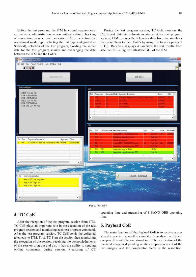
American Journal of Software Engineering and Applications 2015; 4(5): 80-85 82
Before the test program, the ITM functional requirements
are network administration, access authentication, checking
of connection presence with subsystem CoE’s, selecting the
operational mode type, selecting the test type (integrated or
Self-test), selection of the test program, Loading the initial
data for the test program session and exchanging the data
between the ITM and the CoE’s.
During the test program session; TC CoE monitors the
CoE’s and Satellite subsystems status. After test program
session; ITM receives the telemetry data from the simulator
then send them to their CoE’s by using file transfer protocol
(FTP), Receives, displays & archives the test results from
satellite CoE’s. Figure 3 illustrate GUI of the ITM.
Fig. 3. ITM GUI.
4. TC CoE
After the reception of the test program session from ITM,
TC CoE plays an important role in the execution of the test
program session and monitoring each test program command.
After the test program session, TC CoE sends the collected
telemetry to ITM. First, TC Start the session then monitoring
the execution of the session, receiving the acknowledgments
of the session program and also it has the ability to sending
on-line commands during session, Measuring of CE
operating time and measuring of S-BAND OBE operating
time.
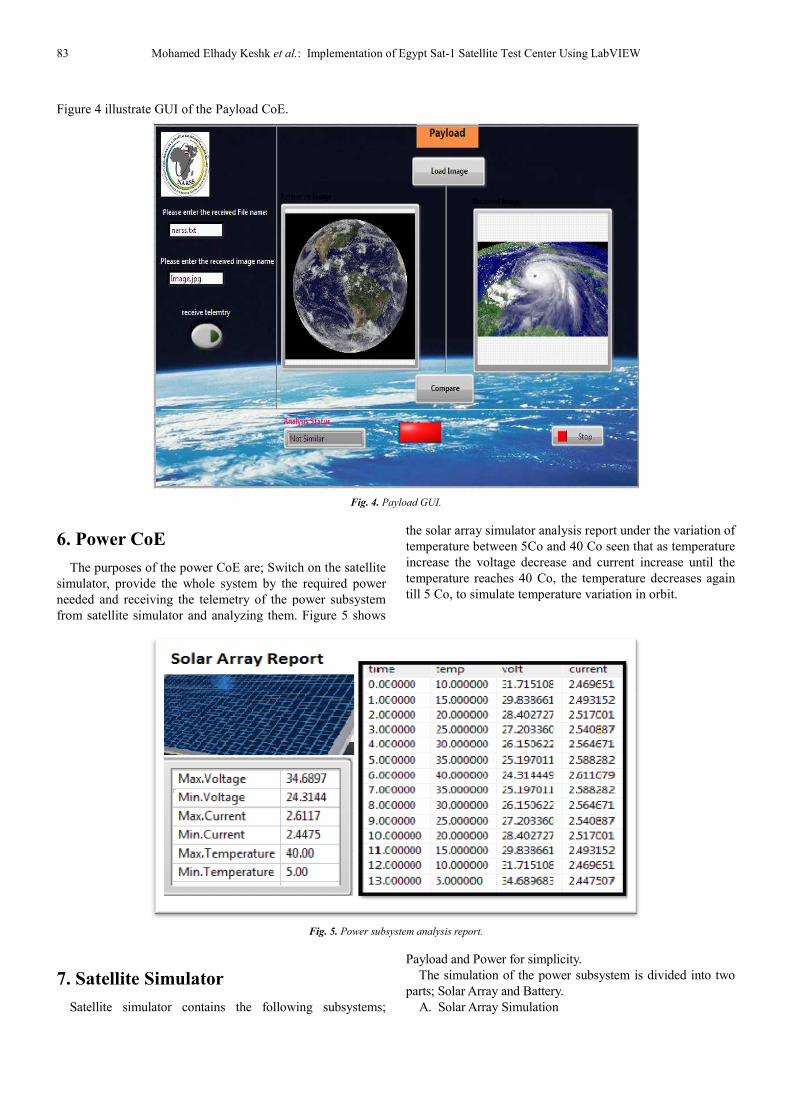
5. Payload CoE
The main function of the Payload CoE is to receive a pre-
stored image in the satellite simulator to analyze, verify and
compare this with the one stored in it. The verification of the
received image is depending on the comparison result of the
two images, and the comparator factor is the resolution.
83 Mohamed Elhady Keshk et al.
Figure 4 illustrate GUI of the Payload CoE.
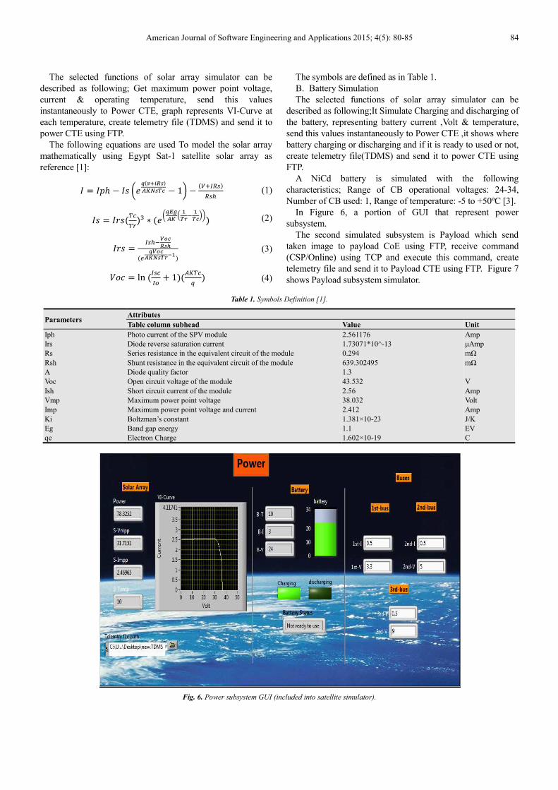
6. Power CoE
The purposes of the power CoE are; Switch on the satellite
simulator, provide the whole system by the required power
needed and receiving the telemetry of the power subsystem
from satellite simulator and analyzing them.
7. Satellite Simulator
Satellite simulator contains the following subsystems
et al.: Implementation of Egypt Sat-1 Satellite Test Center Using LabVIEW
.
Fig. 4. Payload GUI.
itch on the satellite
system by the required power
the telemetry of the power subsystem
from satellite simulator and analyzing them. Figure 5 shows
the solar array simulator analysis report under the variation of
temperature between 5Co and 40
increase the voltage decrease
temperature reaches 40 Co, the temperature decreases
till 5 Co, to simulate temperature variation in orbit.
Fig. 5. Power subsystem analysis report.
Satellite simulator contains the following subsystems;
Payload and Power for simplicity.
The simulation of the power subsystem is divided into two
parts; Solar Array and Battery.
A. Solar Array Simulation
1 Satellite Test Center Using LabVIEW
the solar array simulator analysis report under the variation of
and 40 Co seen that as temperature
and current increase until the
, the temperature decreases again
, to simulate temperature variation in orbit.
Payload and Power for simplicity.
simulation of the power subsystem is divided into two
American Journal of Software Engineering and Applications 2015; 4(5): 80-85 84
The selected functions of solar array simulator can be
described as following; Get maximum power point voltage,
current & operating temperature, send this values
instantaneously to Power CTE, graph represents VI-Curve at
each temperature, create telemetry file (TDMS) and send it to
power CTE using FTP.
The following equations are used To model the solar array
mathematically using Egypt Sat-1 satellite solar array as
reference [1]:
= ℎ − − 1 −
(1)
= !" ∗ $%
& '() '
* (2)
= )+,-
.+,
(/' (3)
012 = ln 6 + 189
: (4)
The symbols are defined as in Table 1.
B. Battery Simulation
The selected functions of solar array simulator can be
described as following;It Simulate Charging and discharging of
the battery, representing battery current ,Volt & temperature,
send this values instantaneously to Power CTE ,it shows where
battery charging or discharging and if it is ready to used or not,
create telemetry file(TDMS) and send it to power CTE using
FTP.
A NiCd battery is simulated with the following
characteristics; Range of CB operational voltages: 24-34,
Number of CB used: 1, Range of temperature: -5 to +50ºC [3].
In Figure 6, a portion of GUI that represent power
subsystem.
The second simulated subsystem is Payload which send
taken image to payload CoE using FTP, receive command
(CSP/Online) using TCP and execute this command, create
telemetry file and send it to Payload CTE using FTP. Figure 7
shows Payload subsystem simulator.
Table 1. Symbols Definition [1].
Parameters Attributes
Table column subhead Value Unit
Iph Photo current of the SPV module 2.561176 Amp
Irs Diode reverse saturation current 1.73071*10^-13 µAmp
Rs Series resistance in the equivalent circuit of the module 0.294 mΩ
Rsh Shunt resistance in the equivalent circuit of the module 639.302495 mΩ
A Diode quality factor 1.3
Voc Open circuit voltage of the module 43.532 V
Ish Short circuit current of the module 2.56 Amp
Vmp Maximum power point voltage 38.032 Volt
Imp Maximum power point voltage and current 2.412 Amp
Ki Boltzman’s constant 1.381×10⁻²³ J/K
Eg Band gap energy 1.1 EV
qe Electron Charge 1.602×10⁻¹⁹ C
Fig. 6. Power subsystem GUI (included into satellite simulator).

85 Mohamed Elhady Keshk et al.: Implementation of Egypt Sat-1 Satellite Test Center Using LabVIEW
Fig. 7. Payload GUI (included into satellite simulator).
8. Conclusion
In this paper a new trend that using LabView program
running on NI machine is used to implement satellite test
center prototype with less hardware, development time,
manpower and cost. From the results it is found that the new
trend capable of replacing the existed STC. As a prototype,
one subsystem is completely implemented (ITM) and the
other test center subsystems are simulated with some of its
functions and from the session that done and the results, it is
found that the proposed STC is work properly.
References
[1] M.S. El-Negamy, M.B. Eteiba 1 and G.M. El-Bayoumi, “Modeling and Simulation of Egyptsat-1 Satellite System Powered by Photovoltaic Module”, Journal of American Science p. 110-116, Vol. 9, No.1, 2013.
[2] Dr. J. Abdul Jaleel, Nazar. A, Omega A R, “Simulation on Maximum Power Point Tracking of the Photovoltaic Module using LabVIEW”, International Journal of Advanced Research in Electrical, Electronics and Instrumentation Engineering, Vol. 1, Issue 3, p.190-199, September 2012.
[3] M. Zahran, M. Okasha and Galina A. Ivanova, “Assessment of Earth Remote Sensing Microsatellite Power Subsystem Capability during Detumbling and Nominal Modes”, Journal of Power Electronics, Vol. 6, No. 1, January 2006.
[4] “Flight and Camera Electronics for a Satellite System - A NI Multisim National Lab Application”, www.ni.com/white-paper/7829/en/, access: Oct 06, 2013.
[5] F. Musso, F. Bresciani, L. Bonino, S. Cesare, “NASA uses NI LabVIEW to save time, reduce costs in automated testing of Micro shutters”, military aerospace solutions Conference, pp. 60-62, 2007.
[6] “Building a Satellite Navigation Test Platform Using the NI Vector Signal Transceiver”www.sine.ni.com/cs/app/doc/p/id/cs-16256.
[7] G. Huang, A. Soghoyan, D. Akopian, P. Chen, A. Samant, “A Land Mobile Channel Modeling in LabVIEW”, IEEE SMC, San Antonio, TX, pp. 4575-4580, 2009.
[8] “Galileo Receiver Testing Based on LabVIEW and NI RF Hardware”, www.sine.ni.com/cs/app/doc/p/id/cs-15551.
[9] Arpine Soghoyan, Grant Huang, Jayanthi Narisetty, David Akopian, “A Comprehensive Labview-Based A-GPS Receiver and Integrated Development, Simulation and Testing Platform”, www.researchgate.net/publication/258567337, jan.2011.
[10] National Instruments FPGA, www.ni.com/fpga/.