Implementation of Components and Circuits - UPC · PDF fileImplementation of Components and...
35
Implementation of Components and Circuits -Fundamental concepts -Examples Outline Layout basic concepts and examples Layout vs. Schematic: origin of differences Fabrication Design Design rules Layout of large area components Layout for matching Effects of Layout on IC reliability Layout for reliability
Transcript of Implementation of Components and Circuits - UPC · PDF fileImplementation of Components and...

1
Implementation of Components and Circuits
-Fundamental concepts-Examples
Outline
Layout basic concepts and examplesLayout vs. Schematic: origin of differences
FabricationDesign
Design rulesLayout of large area componentsLayout for matchingEffects of Layout on IC reliabilityLayout for reliability

2
Floorplan
Sketch of the layoutEstimation of the IC areaTechnology dependent
List of components –subcircuits
ViewLibrary - models
Physical layers available
Pad limited vs. Core limited designs
PAD RING Scribe street
CORE CORE
Floorplan of a communications SoC (left) and microprocessor (right)
Pad digital,1.2 µm CMOS
A/D converter, 6 bits, 175 Msamples/s
PadsProvide surface for bond-wire solderingInclude I/O protection circuitry

3
Layouts
Digital logic: automatic place & route, use of standard cellsAnalog & High Performance: aided manual designComponents with multiple physical implementations
ResistorsCapacitorsBipolar transistorsPower components
Example of components: transistors
Single-gate NMOS, 0.35 µm
Lateral BJT, 0.35 µmVertical NPN BJT, 0.35 µm
Multiple-gate NMOS, 0.35 µm

4
Example of components: passives
N Diffusion resistor Polysilicon resistor
Polysilicon capacitor
P-cellsNMOS transistor Polysilicon capacitor

5
Designing a layout: CAD Tools
Layout design aids in nowadays CAD Tools:Library of components’ layouts (Design Kit)Parameterized layoutsAutomatic layout generation (Place & route)Layout vs. SchematicRules checkingExtractor and layout simulation
Is the proposed layout a good layout?
Designing a layout: CAD Tools
A good layout must be:Ease manufacturability (increase yield)Robust to variationsRobust to gradients (matching)Robust against perturbationsRobust against other undesired phenomena

6
Illuminator: can be Krypton Floride (KrF, λ=248 nm), Argon Floride (ArF, λ=193 nm), Fluorine (F2, λ=157 nm).
Condenser Lens: focuses light on 4x (or 5x) mask
Photomask: made of fused quartz (aka. fused silica)
Projection lens: focuses light on wafercharacterized by its numerical aperture NA
Lithography from C
hiang, Kaw
a, “Design and M
anufacturability and Yield for N
ano-Scale CM
OS
”, Springer 2007
Definition of numerical aperture NA where n is a diffraction index:1 for air∼1.5 for water, oils
Rayleigh’s equations:
where k1, k2 depend on the quality of the photolithography system(typ. k1 ∼ 0,25 – 0,7, k2 ∼ 0,5)
Lithography
sinNA n α= ⋅
1resolution kNAλ
= 2 2( )depth of focus DOF kNAλ
=
from C
hiang, Kaw
a, “Design and M
anufacturability and Yield for N
ano-Scale CM
OS
”, Springer 2007

7
• Example: which is the critical dimension that can be achieved withλ=248 nm?
Reasonable NA for air is 0,8Guess k1=0,4
• Example: which is the critical dimension that can be achieved withλ=193 nm?
Reasonable NA for air is 0,8Guess k1=0,3
Lithography
2480,4 1240,8nmresolution nm= =
1930,3 720,8nmresolution nm= =
• 436 nm: used down to 3 µm technologies
• 365 nm: used down to 0,6 µm technologies
• 248 nm: used down to 130 nm technologies
• 193 nm in air (dry lithography)
Used in technologies down to 90 nm(still in use for some layers in 65 nm, 45 nm...)
Lithography

8
• 436 nm: used down to 3 µm technologies
• 365 nm: used down to 0,6 µm technologies
• 248 nm: used down to 130 nm technologies
• 193 nm in air (dry lithography)
• 157 nm: needs special lens materials
Abandoned definitively in 2005 (dueto technical difficulties associated with the
mask and photoresist materials for thiswavelength; also for the economical cost)
Lithography
Optimistic forecast: ready for22 nm technology node
(∼2011)
Lithography• 436 nm: used down to 3 µm technologies
• 365 nm: used down to 0,6 µm technologies
• 248 nm: used down to 130 nm technologies
• 193 nm in air (dry lithography)
• 157 nm: needs special lens materials
• EUV (λ=13 nm). New approach: mirrors, no lenses

9
Used in 65 nm, 45 nm, (32 nm) technology nodes (NA 1.1 → 1.3)
Lithography• 436 nm: used down to 3 µm technologies
• 365 nm: used down to 0,6 µm technologies
• 248 nm: used down to 130 nm technologies
• 193 nm in air (dry lithography)
• 193 nm in liquid (immersion lithography)
Double patterning: generate a singlelayer by using two masks
Double exposure
Heterogeneous maskSpacer mask
• 193 nm in air (dry lithography)
• 193 nm in liquid (immersion lithography)
Lithography
Used in 65 nm, 45 nm, technology nodes

10
Lithography
Manufacturing: subwavelength gap10
1
0.1
1980 1990 2000 2008
Silicon feature size
Lithography Wavelength
436nm365nm
193nm0.25µm
0.13µm
0.6µm
3µm
0.05µm
ABOVE WAVELENGTH SUB WAVELENGTH
target layout
result
⇒ Increased difraction effects!
from Massimo Conti, BCN 2006

11
Differences between layout and Circuit (I)
Fabrication process limitations
Lateral diffusionEtching under protectionBoundary dependent etchingThree-dimensional effects
Chemical Mechanical Polishing (CMP)Surface topography
Differences between layout and Circuit (II)
Fabrication process limitations
Narrowing after annealingInherent grain variabilityProximity effects
Errors and limitationsMask productionsMask alignment
Oxide variations over a 20 Å nominal oxide thickness

12
Differences between layout and Circuit (III)
Absolute accuracy of physical parameters
Controlled at technological levelSimulation: Process variation
222
2
222
2
2
)(
)(
DSWLA
V
DSWLA
T
TV
VT +=
+=
σ
ββσ
ββ
DL
W
from Massimo Conti, BCN 2006
Differences between layout and Circuit (III)
Absolute accuracy of physical parameters
from Franco Maloberti, “Layout of Analog CMOS ICs”
interlayerdistance tox
width W
length L
dielectricox
L WCt
ε ⋅=
2 22 2 2dielectric ox
dielectric ox
tC L WC t L W
εε
= + + + ∆ ∆ ∆ ∆ ∆
• oxide damage• impurities• temperature• stress• bias conditions
• growth rate• grain size
• etching inaccuracy• mask alignment

13
Differences between layout and Circuit (IV)Relative inaccuracies of physical parameters
Gradients, local variationsCompensated with suitable layout techniques
Crystal orientation variations
Components required to be laid in a determined orientation
Pressure gradients
Thermal gradients
Differences between layout and Circuit (IV)
W=L= 0.5 µm d= 5µm W=L= 10 µm d= 5µm
W=L= 10µm d= 100µmW=L= 0.5 µm d= 100µm
Example: normalized drain current dispersions of 2 MOSFETs for different geometries and distances
from Massimo Conti, BCN 2006
Inaccuracy in absolute value, but matched devices
Inaccuracy in absolute value, and mismatched devices

14
Differences between layout and Circuit (V)
Parasitic couplingCapacitive couplingCouplings through the power supplyCouplings through the substrate
Parasitic resistancesContactsInterconnect
What you get is not what you draw!
Many of the systematic inaccuracies can be avoided through good layout style.
But designers must understand the limitations and apply design techniques to mitigate these effects.

15
Corrections performed by the foundry
Some manufacturing distortions can be predicted and fixed by introducing modifications to the mask
OPC: Optical Proximity Correction
From “Nano-CMOS Circuit and Physical Design”, Wong et al, IEEE Press
Corrections performed by the foundry
From “Nano-CMOS Circuit and Physical Design”, Wong et al, IEEE Press
Examples of corrections
automatically introduced by a OPC
algorithm to the shapes in the mask

16
Corrections performed by the foundry
From Intel Ireland
This top down SEM image was taken without any OPC. The pullback over the contact is clearly seen
This image of the same structure was
taken with OPC implemented on the mask. Good contact
coverage can be seen.
Design for manufacturability: design rules:
Example: Poly 1
17
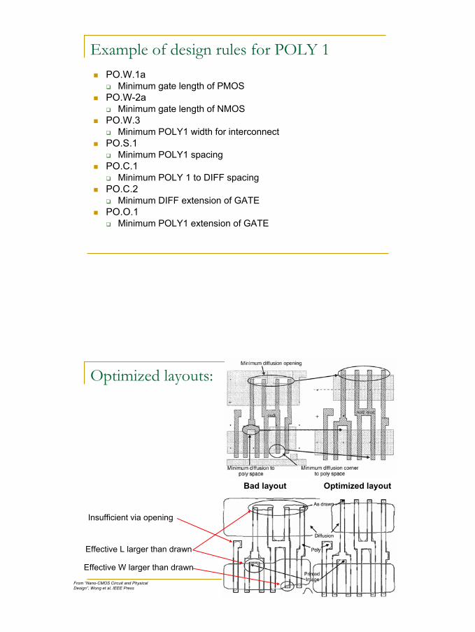
Example of design rules for POLY 1PO.W.1a
Minimum gate length of PMOSPO.W-2a
Minimum gate length of NMOSPO.W.3
Minimum POLY1 width for interconnectPO.S.1
Minimum POLY1 spacingPO.C.1
Minimum POLY 1 to DIFF spacingPO.C.2
Minimum DIFF extension of GATEPO.O.1
Minimum POLY1 extension of GATE
Optimized layouts:
Bad layout Optimized layout
Effective L larger than drawn
Effective W larger than drawn
Insufficient via opening
From “Nano-CMOS Circuit and Physical Design”, Wong et al, IEEE Press

18
Optimized layouts:
Optimized layout
Optimize efficiency of vias/contacts
All transistors in the same orientation
• Better control of manufacturing• Easier lithography (mask)
corrections
Maximize number of vias/contacts
From “Nano-CMOS Circuit and Physical Design”, Wong et al, IEEE Press
Optimized layouts:
Possible shortcircuit of nodes A and B due to diffussion flaring and mask misalingment
Possible shortcircuit due to diffussion flaring
Possible shortcircuit due to poly flaring
From “Nano-CMOS Circuit and Physical Design”, Wong et al, IEEE Press

19
Layout for matching
Devices with the same orientation
Current in the same direction
Gradients increase with distanceSame orientation towards physical gradients
Device 1
Device 2
Dissipatingdevice
T1
T2
Dev
ice
1
Dev
ice
2
Dissipatingdevice
T1
T2
Layout for matchingInterdigitated structures
Resistors R1 and R2
MOS transistors M1 and M2

20
Layout for matchingInterdigitated structures
Different symmetry axes for transistors A and B
Same symmetry axis for transistors A and B
from Franco Maloberti, “Layout of Analog CMOS ICs”
Layout for matching
Common centroid:

21
Layout for matching: Common centroid
CoincidenceCentroids of matched devices should coincide
SymmetryArray symmetric around both X and Y axis
DispersionSegment of each device distributed throughout the array as uniformly as possible
CompactnessIdeally: array should be square
Layout for matching: Common centroid
from Franco Maloberti, “Layout of Analog CMOS ICs”

22
Layout for matching: Use of dummiesDummies
Use dummy devices to provide the same contour conditions.Ground dummies (do not let them float)Dummies can be full (shorted) devices, or part of themBeware of their parasitics!
Layout for matching: Use of dummiesReference cell
Use multiple basic transistors instead of different sizesSame W, same orientation,

23
Design of large area components
MOS TransistorsMultiple gates to minimize serial resistanceMultiple contacts to minimize serial resistance
No big contacts!!!“stacked” structures
Lower parasitic capacitancesLower area
Analogue applicationsAvoid minimum size
Automatically generated layoutsAMS, 0.35 microns, 10/0.35
Design of large area components
ResistancesBended structuresDummy structures45 degrees (avoid non laminar current flow)Contacts
Current in the same directionMultiple contacts
Piezoresistive effect
Resistor: 5K, 275x3 sq microns.Example of “good” and “bad” layout

24
Layout for matching: interconnectsCMP:
Erosion effect: denser interconnects will have higher R
From “Nano-CMOS Circuit and Physical Design”, Wong et al, IEEE Press
Rules for matchingSame W and L: Vary MCapacitors
Multiple M of a capacitance reference CR
Ms: Even (factors of 4!!)Clean and balanced routing
IR dropsParasitic capacitance and couplingsKelvin connections
Avoid minimum sizing and overlappingUse dummy structuresSame spacing in interconnects

25
Layout Strategies for circuit reliability (I)
ElectromigrationElectromigration is the transport of material caused by the gradual movement of the ions in a conductor due to the momentum transfer between conducting electrons and diffusing metal atomsDependent on:
TemperatureCurrent densityConductor ShapeMaterial
Layout for reliability: Electromigration
Exist technological preventive measuresType of metal layer (Cu better than Al)Oxidation (better over field oxide)Use of protective overcoats
Width of interconnections: M µm/mATypical M: between 1 and 0.5
Maximum current per contact and vias

26
Layout Strategies for circuit reliability (II)
Latch-upA latchup is the inadvertent creation of a low-impedancepath between the power supply rails of an electronic component, triggering a parasitic device, which then acts as a short circuit, leading to malfunctioning of the part and perhaps even its destruction with the overcurrent
Layout for reliability: Latch-upActivation:
If voltages higher than VDDIf voltages lower than GNDIf currents through the well/substrateI/O Circuitry more sensitive
Elimination of minority carriersGuard ringsBiased with low resistances
Reduce beta parasitic transistors. Reduce forward bias resistance

27
Layout for reliability: Latch-upReduce forward bias resistance:
Rules:
Layout for reliability: Latch-up
XXXX
X
I/O Circuitry more sensitive
I/O transistorssurroundedby pick-upsand guard
rings
I/O and core transistors separated by guard
rings

28
Layout Strategies for circuit reliability (III)
CMPChemical Mechanical Polishing or Chemical Mechanical PlanarizationRemoval any irregular topographySurface within the depth of field of a photolithography system.
Layout for reliability: CMP
Example: MOSIS 0.25(TSMC)
Design rules:Minimum % coverage ofMetal layersPolysilicon layersCapacitor Layers

29
Layout for reliability: CMP
2µ 2µ
5µ
All Metal Fill pattern(staked M1, M2, M3, M4 )
Poly 1 Fill pattern as metal
Dummy patterns are distributed over the chip as uniformly as possible in order to reach the required coverage for each
material (Metal 1, 2, 3, 4, 5, Poly 1 and CTM (capacitor top metal) )
Layout for reliability: CMP
Pattern for M1
Example: 4-metal technology
1. Orientation of dummy pattern should be perpendicular to previous layer
2. Top layer should have larger dummy pattern
Pattern for M2 Pattern for M3 Pattern for M4 (top)

30
Layout for reliability: CMP
Example in a 0,18 µm technology:
• Patterns generated automatically by the foundry
• User has masks to define areas that will NOT be filled with patterns(Ex: inductors, capacitors, test strcutures, etc)
Layout for reliability: CMPExample of Transmission line in M7 with dummy metals below :
Open question: How do dummy metal fills affect transmission lines
and passives ?
“A B
idirectional-andM
ulti-Drop-Transm
ission-LineInterconnect…
”, IE
EE
JSS
C A
pril2008

31
Layout for reliability: CMP
Proposal: slow-wave transmission lines- Low Q- Small area- Necessary grid fulfills metal coverage
Borrem
anset al., “V
CO
designfor60 G
Hz
applicationsusing
differentialshieldedinductors
in 0.13 µmC
MO
S”, R
FIC’08
Layout for reliability: CMPSlots
Act both as stress releasers and to minimize dishingSlots in metals W> Value (tech. dependent)Possible library of components
CornersPads
dishing

32
Layout Strategies for circuit reliability (IV)
Antenna Effects or Plasma-Induced damageThe "Antenna Rules" deal with process induced gate oxide damage. Reactive ion-etching may induce charges to exposed polysilicon and metal structures. If these structures are connected to gates (and not to diffusion), they may develop potentials sufficiently large to cause Fowler Nordheim current to flow through the thin oxide
Layout for reliability: Antenna
Vulnerability depends on ratio between periphery/area of trapping material to gate areaFab. 1: Rules Poly and metal layers (including contacts)
Max perimeter ratio of field poly to active polyMax perimeter ratio of floating metals to active polyMax drawn area of CO vs. Active Poly
( )[ ]22
1112LWZWLratio
⋅⋅+
=
Poly and Metal ratio definition
22area a)Contact(Vi
LWratio
⋅=
Contact and via ratio definition

33
Layout for reliability: Antenna
Fab. 2Maximum floating (Poly,Metal) Edge area ratio to active area ratio.
Use of “leakers” and metal jumpers
Layout Strategies for circuit reliability (V)
ESDElectrostatic DischargeDamage in dielectrics due to IC manipulation (mainly gate oxide)

34
Layout for reliability: Analog PAD
Diodes and resistors for ESD protectionReverse diodes: Parasitic capacitance!!!
Example of RF PAD without diodes

35
References
The art of Analog Layout, 2nd Edition. Alan Hastings. Ed. Prentice HallNano-CMOS Circuit and Physical Design. B.P. Wong et al. Wiley-Interscience, IEEE PressCMOS Circuit Design, Layout and Simulation. R. J. Baker. Wiley IEEE PressLayout of Analog and Mixed Analog-Digital Circuits. Franco Maloberti.http://www.wikipedia.org/