Implementation of a DSPACE-based standalone … of a DSPACE-based standalone renewable energy ......
11
ORIGINAL RESEARCH Implementation of a DSPACE-based standalone renewable energy supply feeding an isolated load Mohamed Barara 1 • Chimezie Adiuku 2 • Abdul Rhaiman Beig 2 • Khalifa Hasan Alhosani 2 • Naji Al Sayari 2 • Mohamed Akherraz 1 Received: 18 September 2015 / Accepted: 1 March 2016 / Published online: 17 March 2016 Ó The Author(s) 2016. This article is published with open access at Springerlink.com Abstract This paper deals with standalone small power generation employing three self-excited induction genera- tors under varying speeds feeding an isolated load. The proposed system utilizes three-level cascaded H-bridge inverter for the three generators. The control scheme has the capability of regulating the output voltage for balanced operation of a three-phase isolated load under variable speed. The proposed control can be implemented using DSPACE 1104, and the experimental results are presented to demonstrate the effectiveness of the proposed controller for an isolated generating system. Keywords Renewable energy Multilevel inverter Voltage control List of symbols R s Stator resistance R r Rotor resistance l s Stator leakage inductance l r Rotor leakage inductance L m Mutual inductance V cd ; V cq Direct and quadrature axes stator i ds ; i qs i dr ; i qr Direct and quadrature axes stator and rotor current, respectively c AC capacitance P Number of poles K d and K q Constants which represent the initially induced voltages along the d-axis and q-axis M Modulation index V r Amplitude of the reference signal V c Amplitude of the control signal V s Input voltage r Width of the mth pulse p Number of pulses per half-cycle V rms RMS voltage I m Magnetizing current SPWM Sinusoidal pulse width modulation Introduction Recently, a lot of research has taken place in the design and control of renewable energy systems such as solar, wind, hydraulic and biomass, because they are sustainable, cost- effective and alternatives for conventional energy sources. For isolated and remote areas, it may not be practical or economically viable to provide a connection to the distribution grid system, where utility lines are uneconomical to install due to the terrain and geographical condition difficulties. In the literature, regarding the efficient integration of renewable sources for supplying remote power systems, Sonia Leva [1, 2] presents a techno-economic analysis about the possible implementation of hybrid systems (photovoltaic and wind energy) on an existing plant for supplying isolated applications such as industrial applica- tions related to telecommunications. In terms of the sta- bility of an isolated system, the author [3] presents a theoretical approach for the dynamic stability analysis in case power-quality disturbances such as unbalances, har- monics, and inter harmonics take place. The pollution, & Mohamed Barara [email protected] 1 Department of Electrical Engineering, Mohamed V University, EMI, Rabat, Morocco 2 Department of Electrical Engineering, The Petroleum Institute, Abu Dhabi, United Arab Emirates 123 Int J Energy Environ Eng (2016) 7:125–135 DOI 10.1007/s40095-016-0207-3
-
Upload
duonghuong -
Category
Documents
-
view
219 -
download
2
Transcript of Implementation of a DSPACE-based standalone … of a DSPACE-based standalone renewable energy ......

ORIGINAL RESEARCH
Implementation of a DSPACE-based standalone renewable energysupply feeding an isolated load
Mohamed Barara1 • Chimezie Adiuku2 • Abdul Rhaiman Beig2 •
Khalifa Hasan Alhosani2 • Naji Al Sayari2 • Mohamed Akherraz1
Received: 18 September 2015 / Accepted: 1 March 2016 / Published online: 17 March 2016
� The Author(s) 2016. This article is published with open access at Springerlink.com
Abstract This paper deals with standalone small power
generation employing three self-excited induction genera-
tors under varying speeds feeding an isolated load. The
proposed system utilizes three-level cascaded H-bridge
inverter for the three generators. The control scheme has
the capability of regulating the output voltage for balanced
operation of a three-phase isolated load under variable
speed. The proposed control can be implemented using
DSPACE 1104, and the experimental results are presented
to demonstrate the effectiveness of the proposed controller
for an isolated generating system.
Keywords Renewable energy � Multilevel inverter �Voltage control
List of symbols
Rs Stator resistance
Rr Rotor resistance
ls Stator leakage inductance
lr Rotor leakage inductance
Lm Mutual inductance
Vcd;Vcq Direct and quadrature axes stator
ids; iqsidr; iqr Direct and quadrature axes stator and rotor
current, respectively
c AC capacitance
P Number of poles
Kd and Kq Constants which represent the initially
induced voltages along the d-axis and q-axis
M Modulation index
Vr Amplitude of the reference signal
Vc Amplitude of the control signal
Vs Input voltage
r Width of the mth pulse
p Number of pulses per half-cycle
Vrms RMS voltage
Im Magnetizing current
SPWM Sinusoidal pulse width modulation
Introduction
Recently, a lot of research has taken place in the design and
control of renewable energy systems such as solar, wind,
hydraulic and biomass, because they are sustainable, cost-
effective and alternatives for conventional energy sources.
For isolated and remote areas, it may not be practical or
economically viable to provide a connection to the distribution
grid system, where utility lines are uneconomical to install due
to the terrain and geographical condition difficulties.
In the literature, regarding the efficient integration of
renewable sources for supplying remote power systems,
Sonia Leva [1, 2] presents a techno-economic analysis
about the possible implementation of hybrid systems
(photovoltaic and wind energy) on an existing plant for
supplying isolated applications such as industrial applica-
tions related to telecommunications. In terms of the sta-
bility of an isolated system, the author [3] presents a
theoretical approach for the dynamic stability analysis in
case power-quality disturbances such as unbalances, har-
monics, and inter harmonics take place. The pollution,
& Mohamed Barara
1 Department of Electrical Engineering, Mohamed V
University, EMI, Rabat, Morocco
2 Department of Electrical Engineering, The Petroleum
Institute, Abu Dhabi, United Arab Emirates
123
Int J Energy Environ Eng (2016) 7:125–135
DOI 10.1007/s40095-016-0207-3

resulting from the current and voltage the system acquires,
may cause stability problems especially in isolated electric
plants where small generators, supply motor drives, static
converters, or nonlinear loads are involved. The present
study constitutes a technical investigation, aiming at
hardware implementation, to control small power genera-
tors, based on self-excited induction generators, and pro-
vides a versatile way to investigate different hybrid
schemes of renewable energy generation fuel cell and PV.
Self-excited induction generators (SIEG) have been
found to be very suitable for small power generation by
small or micro-hydro as well as wind systems; they provide
a promising solution for isolated areas to generate electrical
energy because of the low price, mechanical simplicity and
robust structure.
The use of cage induction machine connected to the
fixed bank capacity has the advantage of simplicity in
implementation and low cost due to the absence of a static
converter. However, this configuration allows operating
limits which must be taken into account, especially chan-
ges in amplitude and voltage frequency during load and
speed variations [4]. In the literature, many authors [5–9]
have discussed different criteria for selecting the limiting
value of capacitance and speed for successful operation of
SEIG under various conditions.
With regard to the drawback of this machine, the output
voltage is affected by the load and speed condition. A
number of schemes have been suggested for regulating the
terminal voltage and have been reported in literature [10–
16]. Since there is limited work published on the applica-
tion of multilevel for the control of several SEIGs working
in parallel and independent. Also, the literature is very
limited on the application of H-bridge inverters in stan-
dalone systems, where they have several advantages,
namely low distortion voltages and currents and low
switching losses and the power can be efficiently trans-
ferred from different generators with better power quality.
The aim of this paper is to examine this technology for
small power generation using self-excited induction gen-
erators. It is hoped that this will draw the attention of
researchers toward its application, especially for remote
and isolated locations. An attempt is made to control the
terminal voltage and frequency from the number of SIEGs
connected to multilevel converters.
Multilevel converters have been under research and
development for more than three decades and have found
successful industrial application. In recent years, many
publications have addressed multilevel converter technol-
ogy and stressed the growing importance of multilevel
converters for high-power applications [17]. The most
popular multilevel converter topologies are flying capacitor
(FC), cascaded H-bridge (CHB) converters and neutral
point clamped (NPC).
The cascaded H-bridge multilevel topology is the most
convenient model compared to other topologies according
to the required switching devices. This topology requires
separate DC sources for each H-bridge which is an
advantage for applications such as renewable or alternative
energy sources, because it offers a modular solution by
collecting large numbers of PV panels or generator as
isolated DC sources, which allows generating a large
number of voltage levels in the output. However, this
advantage comes along with drawbacks, which are the
inherent power imbalance between generators in each leg
as well as a power imbalance among the different phases of
the inverter [18, 19]; this condition will affect the perfor-
mance of the CHB and load.
In this paper, the two types of imbalances will be
addressed sequentially in the control strategy: first, the
phase imbalanced is compensated through the modification
of the phase references, and the amplitude imbalance is
compensated by generating the same reference voltage,
because the voltage generated by the SIEGs depends
strongly on the variation of the prime mover.
A suitable topology has been proposed, through the
design and control of an inverter for isolated load to effi-
ciently make use of energy from the generators. The pro-
posed inverter includes three H-bridges and four SPWM
switching signals to control each bridge, respectively. The
operating principle and design guidelines of the proposed
scheme are presented along with the performance analysis
and simulation using MATLAB Simulink with three self-
excited induction generators operating at different variable
speeds.
The experimental prototype has been developed for the
validation of the proposed converter system. The Dspace
controller is used to transfer the PWM signals and to feed
back the voltage signals of each phase load voltage. The
error between the reference RMS phase voltage and the
feedback RMS phase voltages are used to effectively
generate proper PWM signals to drive IGBTs of the con-
trolled power converter.
The rest of this paper is organized as follows. The
system configuration for small power generation is pre-
sented in ‘‘Configuration of the proposed standalone sys-
tem’’. The control scheme and hardware configuration are
presented in ‘‘Configuration control algorithm’’. The last
section shows the simulation, experiment results and
discussion.
Configuration of the proposed standalone system
The system is designed for an isolated location. The
complete configuration of the proposed generation system
using an SEIG is shown in Fig. 1. The self-excited
126 Int J Energy Environ Eng (2016) 7:125–135
123

induction generator using three-phase AC capacitors can
start its voltage buildup from a remnant magnetic flux in
the core. This voltage buildup starts when the induction
generators are driven at a given speed and an appropriate
capacitance is connected at its terminals. The DC sources
of each single-phase H-Bridge inverter are obtained from
three-phase diode rectifiers powered by self-excited
induction generators.
The following sections present the modelling of all
subsystems of the proposed system. The main components
are SIEG, three-phase diode rectifier, three-level cascaded
H-bridge inverter and AC load.
Self-excited induction generator
Including initial conditions, i.e. initial voltage in the
capacitors and remnant magnetic flux in the core, one can
obtain the following differential equation. The state-space
form of the induction generator in the q–d synchronously
rotating reference frame is given by [20]:
d
dtI ¼ AI þ B
I ¼
iqs
ids
iqr
idr
26664
37775; B ¼
LmKq �LrVcq
LmKd �LrVcd
LmVcq �LsKq
LmVcd �LsKd
26664
37775;
A ¼ 1
L
�LrRs �L2mwrLmRr �LmwrLr
L2mwr �LsRsLmwr LrLmRr
LmRsLswrLm �LsRr �LswrLr
�LswrLrLmRs �LswrLr �LsRr
26664
37775 ð1Þ
where L ¼ LrLs � L2m:The excitation system model is:
Vcq ¼ 1=cðiqs irlqÞdt; ð2Þ
Vcd ¼ 1=cðids irldÞdt; ð3Þ
where ird and irq are input currents of the three-phase diode
bridge rectifier.
Fig. 1 Configuration of the proposed standalone system
Int J Energy Environ Eng (2016) 7:125–135 127
123

The instantaneous amplitude of the magnetizing current
of the SEIG is computed as:
Im ¼ffiffiffiffiffiffiffiffiffiffiffiffiffiffiffiffiffiffiffiffiffiffiffiffiffiffiffiffiffiffiffiffiffiffiffiffiffiffiffiffiffiffiffiffiffiffiffiðiqs þ iqrÞ2 þ ðids þ idrÞ2
q: ð4Þ
Three-phase diode rectifier
Three-phase diode bridge rectifier is used to convert the
variable magnitude, variable frequency voltage at the
induction generator terminal into DC voltage. The circuit
consists of six diodes, a top group of three diodes and a
bottom group of three diodes.
Three-level cascaded H-bridge inverter
Cascaded H-bridge inverter is seen as the most suit-
able topology for the integration of the renewable energy,
since the separate DC sources that it requires can be
directly fed by PV arrays, wind turbine or fuel cells. The
three-level cascaded H-bridge inverter consists of three
identical single-phase H-bridges in each phase (HB_A,
HB_B and HB_C). Each HB is supplied by a separate DC
source, where V is the unit voltage. Each HB generates
three voltages at the output: ?V, 0 and -V, Each H-bridge
has three-switching states as defined in Table 1.
Configuration control algorithm
The control system permits the independent control for
each H-bridge inverter; three PI controllers are necessary
for independent control of each output of H-Bridge as
shown in Fig. 2.
The H-bridge topology has a left leg and a right leg.
The phase shift between the upper H-bridge and the
lower H-bridge is 90� and between each H-bridge 120�.The reference of each output voltage is the same for the
three H-bridges. A two sinusoidal reference signal is
compared to a triangular waveform to generate switching
Table 1 Switching state
definitions for phase RState vRo Status of switches
?1 ?V S1, S2 are on, and S3, S4 are off
0 0 S1, S3 are on, and S2, S4 are off OR S2, S4 are on, and S1, S3 are off
-1 -V S3, S4 are on, and S1, S2 are off
Fig. 2 Control strategy of the
proposed system
a b c
0 1 2 3 4 5 6 7 8130
140
150
160
170
time (s)
Ro
tor
Sp
eed
0 1 2 3 4 5 6 7 8150
155
160
165
170
time (s)
Ro
tot
spee
d
0 1 2 3 4 5 6 7 8140
145
150
155
160
time (s)
Ro
tor
spee
d
Fig. 3 Variation rotor speed of the three generators: a SIEG 1, b SIEG 2, c SIEG 3
128 Int J Energy Environ Eng (2016) 7:125–135
123

signals of inverter block in the SPWM modulation
technique. The sinusoidal waveform is known as mod-
ulating signal and its frequency is 50 Hz. The triangular
waveform is generated at a high frequency as carrier of
modulation. The RMS output voltage of the H-bridge
can be varied by changing the modulation index, M. The
conventional PI controller is employed to adjust the
equivalent modulation index.
M ¼ Vr
Vc
; ð5Þ
where, Vr is the amplitude of the reference signal and Vc is
the amplitude of the control signal.
a b c
Zoom (a) Zoom (b) Zoom (c)
0 2 4 6 8-400
-200
0
200
400
time (s)
Sta
tor
volt
age
0 2 4 6 8
-400
-200
0
200
400
time (s)
Sta
tor
volt
age
0 2 4 6 8-400
-200
0
200
400
time (s)
Sta
tor
volt
age
1.4 1.45 1.5 1.55 1.6-400
-200
0
200
400
time (s)2.9 2.95 3 3.05 3.1
-400
-200
0
200
400
time (s)
4.4 4.42 4.44 4.46 4.48 4.5 4.52 4.54 4.56 4.58 4.6-400
-300
-200
-100
0
100
200
300
400
time (s)
Fig. 4 Terminal stator voltage of the three generators: a SIEG 1, b SIEG 2, c SIEG 3
0 1 2 3 4 5 6 7 80
100
200
300
400
500
600
700
800
time (s)
Fig. 5 DC link voltage of the
three generators: blue (SIEG 1),
red (SIEG 2), green (SIEG 3)
0 1 2 3 4 5 6 7 80
50
110
150
230250
300
RM
S v
olta
ge
t(s)
Fig. 6 RMS control voltages of the three-cascade H-bridge
Int J Energy Environ Eng (2016) 7:125–135 129
123
The RMS output voltage is defined as [21]:
Vrms ¼X2p
M¼1
rp
!Vs; ð6Þ
where Vs is the input voltage, r the width of the mth pulse
and p the number of pulses per half-cycle.
Results and discussion
The feasibility of the proposed control method has been
investigated and verified through computer simulations and
experimental results.
Simulation results
MATLAB/Simulink� modelling is used to examine the
effectiveness of the proposed control. The residual mag-
netism in the machine is taken into account in the simu-
lation process, because it is not possible for the induction
generator to be self-excited without it. The three induction
generators are rated at 3.6 kW. The relationship between
magnetizing inductance (Lm) and phase voltage for
induction machine was obtained experimentally by [22]:
Lm = 1.56e-11.v4 ? 2.44e-8.v3 - 1.19e-5.v2 ? 1.42e
-3.v ? 0.245.Fig. 7 Hardware used for experimental evaluation
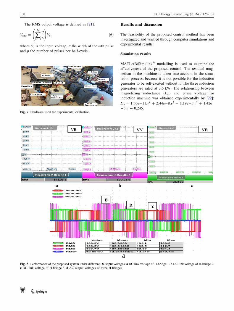
Fig. 8 Performance of the proposed system under different DC input voltages. a DC link voltage of H-bridge 1. b DC link voltage of H-bridge 2.
c DC link voltage of H-bridge 3. d AC output voltages of three H-bridges
130 Int J Energy Environ Eng (2016) 7:125–135
123

The proposed system starts excitation process from
capacitors bank of 60 lF which are connected across the
stator terminals of an induction machine. The global sys-
tem is tested during 8 s, and the three generators are sub-
jected to step change in the rotor speed as shown in Fig. 3
to give variable DC voltage to the input inverter. The
reference RMS voltage of the three H-bridges is set at
230 V and later changed to 110 V after 6 s to show the
effectiveness of the controller. The steady state and
dynamic behaviour of the system under normal conditions
are presented.
Figures 4 and 5 show the effect of the stator terminal
voltage and DC link voltage for three generators under
variation of rotor speed, respectively.
Constant voltage control is effectively achieved by
employing a cascaded three-level H-bridge inverter with
controllable output voltage. Simulation results for control
voltage are presented for the three induction generators
subjected to step changes in the prime mover and reference
setting to demonstrate the validity of the proposed control
scheme. The simulation results of the proposed system
based on three self-excited induction generators under
variation of speed obtained from the downscaled prototype
confirm the merits as show in Fig. 6.
Experimental results
The experimental setup of the proposed system as shown in
Fig. 7 comprises 1.1 kW induction generator driven by an
induction motor (as prime mover). The generator stator
phase output voltages with a capacitor bank for excitation
are connected to three-phase diode rectifiers of an H-bridge
inverter. Two other H-bridge inverters are connected with a
separate isolation transformer. These isolation transformers
are fed with an auto transformer to simulate the behaviour
of output voltage of SIEG, such as variation of the prime
mover. The three output voltages of each cascaded
H-bridge inverter are connected to an isolated load. The
output phase voltages are fed back through an analogue-to-
digital converter (ADC) of the DSPACE. The error
Fig. 9 Performance of the proposed system under different DC input voltages. a DC link voltage of H-bridge 1. b DC link voltage of H-bridge 2.
c DC link voltage of H-bridge 3. d AC output voltages of three H-bridges
Int J Energy Environ Eng (2016) 7:125–135 131
123

between the reference and the feedback signals are passed
through PI controllers to generate the modulation indexes
used for the PWM signals to switch 12 IGBTs of the cas-
caded H-bridge inverter.
Performance of the proposed system with step change
in DC and load
The system operates under standalone mode, and the output
of the converter is connected with different conditions, no
load, a three-phase resistive load and induction motor.
To validate the control scheme in the experiment, the
reference voltage is fixed at 110 V and the experiment is
done under variable and unequal DC voltage through
changing of the speed of SIEG and the source voltages of
the two isolated transformers with an autotransformer.
Measurements are made using the two digital oscillo-
scopes at the same time with capture screens, in which the
first measures the three continuous voltages of the inverter
input and the second measures the three simple voltages
output of the inverter.
Figures 8d and 9d show the experimental performance
of the control scheme for the output voltage under variable
and unequal input DC voltage (Figs. 8a–c, 9a–c) with no
load.
Figures 10d and 11d illustrate the experimental wave-
forms of the output voltage and line current under unequal
DC voltage (Figs. 10a–c, 11a–c) due to variation of source
and rotor speed of SIEG feeding resistive load and induc-
tion motor, respectively.
Figure 12d shows the line to line voltage of three-level
cascade H-bridge feeding an induction motor.
The test experiments are conducted to demonstrate the
response of the close loop system; the modulation index is
changed to achieve the desired RMS phase voltage with
balanced operation of a three phase. The system behaves
with variation in DC link voltage, while the RMS AC
output voltage is maintained constant as evident from
Table 2. It is worth mentioning that the inverter usually
operates with effectiveness for all the five cases as shown
from Figs. 8, 9, 10, 11 and 12.
Fig. 10 Performance of the proposed system under different DC input voltages. a DC link voltage of H-bridge 1. b DC link voltage of H-bridge
2. c DC link voltage of H-bridge 3. d AC output voltages of three H-bridges feeding resistive load blue (line current)
132 Int J Energy Environ Eng (2016) 7:125–135
123

The performance of renewable energy system based
on small power generation working independently and
parallel through voltage regulation is investigated in
experimental results for no load, resistive load and
inductive load. It is shown that the output AC load
voltage can be effectively kept at a fixed value of around
110 V for balanced operation of a three-phase isolated
load regardless of perturbation of source and application
of loads.
In both the simulation and experimental tests, the RMS
voltage effectively tracks to their references even with the
variation and inequality of the DC link. A robust perfor-
mance is obtained. The proposed method can be easily
extended to other renewable source such as the PV system
to achieve optimal performance with good quality.
Conclusion
This study proposes an effective control voltage configu-
ration for three SIEG-based renewable energy supplies
(micro-hydraulic or wind). A comprehensive simulation
study demonstrates the performance of the proposed sys-
tem during variable speed conditions of the three genera-
tors. It has been observed that the controller is capable of
regulating the output voltage.
The specific contribution of this paper is summarized as
follows:
• Suitable topology for application of small power
generation using induction generator in isolated loca-
tion by three-level cascade H-Bridge.
Fig. 11 Performance of the proposed system under different DC input voltages. a DC link voltage of H-bridge 1. b DC link voltage of H-bridge
2. c DC link voltage of H-bridge 3. d AC output voltages of three H-bridge feeding induction motor blue (line current)
Int J Energy Environ Eng (2016) 7:125–135 133
123

• Proposed control scheme for the output voltage regu-
lation of three cascades H-bridge inverter without DC
bus voltage regulation with DC/DC converter in the
input of the H-bridge.
• The system is designed in a flexible and versatile way
for the investigation of different hybrid schemes of
renewable energy generation
Acknowledgments The authors gratefully thank the Power Elec-
tronics Research Lab, the Petroleum Institute, for the facilities and
support for this research. We specially thank Mr. Saikrishna Kanu-
kollu for his valuable assistance in this work.
Open Access This article is distributed under the terms of the
Creative Commons Attribution 4.0 International License (http://crea
tivecommons.org/licenses/by/4.0/), which permits unrestricted use,
distribution, and reproduction in any medium, provided you give
appropriate credit to the original author(s) and the source, provide a
link to the Creative Commons license, and indicate if changes were
made.
References
1. Leva, S., Zaninelli, D.: Hybrid renewable energy-fuel cell sys-
tem: design and performance evaluation. Electr. Power Syst. Res.
79, 316–324 (2009)
2. Iannone, F., Leva, S., Zaninelli, D.: Hybrid photovoltaic and
hybrid photovoltaic-fuel cell system: economic and environ-
mental analysis. In: Power Engineering Society General Meeting,
2005. IEEE, vol. 2, pp. 1503–1509, 12–16 June 2005
3. Leva, S.: Dynamic stability of isolated system in the presence of
PQ disturbances. IEEE Trans. Power Deliv. 23(2), 831–840
(2008)
4. Rekioua, D.: Wind Power Electric Systems, Green Energy and
Technology. Springer, London (2014)
Table 2 Results
Figure V1 V2 V3 Va_rms Vb_rms Vc_rms
No load
8 141.44 139.17 139.12 106.7 108.6 106.6
9 141.59 139.05 222.56 106.2 108.5 107.7
10 250.3 247.63 310.74 107.6 109.8 107.1
With load
11 159.25 157.58 229.13 105.3 107.6 105
12 174.85 173.14 219.54 105.5 108.1 106
Fig. 12 Performance of the proposed system under different DC input voltages. a DC link voltage of H-bridge 1. b DC link voltage of H-bridge
2. c DC link voltage of H-bridge 3. d AC line to line output voltage of H-bridge and current feeding induction motor
134 Int J Energy Environ Eng (2016) 7:125–135
123

5. Chan, T.F.: Capacitance requirements of self-excited induction
generators. IEEE Trans. Energy Convers. 8(2), 304–311 (1993)
6. Al-Jabri, A., Alolah, A.I.: Limits on the performance of the three-
phase self-excited induction generators. IEEE Trans. Energy
Convers. 5, 350–357 (1990)
7. Malik, N.H., Mazi, A.A.: Capacitance requirement for isolated
self-excited generators. IEEE Trans. Energy Convers. 2, 62–69(1987)
8. Chakraborty, C., Bhadra, S.N., Chattopadhyay, A.K.: Excitation
requirements for standalone three-phase self-excited induction
generator. IEEE Trans. Energy Convers. 13(4), 358–365 (1998)
9. Chan, T.F.: Steady-state analysis of selfexcited induction gener-
ators. IEEE Trans. Energy Conversion 9(2), 288–296 (1994)
10. Goel, P.K., Singh, B., Murthy, S.S., Kishore, N.: Isolated wind-
hydro hybrid system using cage generators and battery storage.
IEEE Trans. Ind. Electron. 58(4), 1141–1153 (2011)
11. Wang, L., Chen, H.W., Lee, D.-J.: Implementation of a DSP-
based power converter for a wind induction generator. In: Power
and Energy Society General Meeting—Conversion and Delivery
of Electrical Energy in the 21st Century, 2008 IEEE, pp. 1–6,
20–24 July 2008
12. Chilipi, R.R., Singh, B., Murthy, S.S.: Performance of a self-
excited induction generator with DSTATCOM-DTC drive-based
voltage and frequency controller. IEEE Trans. Energy Convers.
29(3), 545–557 (2014)
13. Wang, L., Lee, D.-J.: Coordination control of an AC-to-DC
converter and a switched excitation capacitor bank for an
autonomous self-excited induction generator in renewable-energy
systems. IEEE Trans. Ind. Electron 50(4), 2828–2836 (2014)
14. Singh, B., Kasal, G.K., Chandra, A., Al Haddad, K.: Voltage and
frequency controller for an autonomous micro hydro generating
system. In: Power and Energy Society General Meeting—Con-
version and Delivery of Electrical Energy in the 21st Century,
2008 IEEE, pp. 1–9, 20–24
15. Chen, W.-L., Hsu, Y.-Y.: Experimental evaluation of an isolated
induction generator with voltage and frequency control. In:
Power Electronics, International Symposium on Electrical
Drives, Automation and Motion, SPEEDAM 2006., May 2006,
pp. 497–502, 23–26
16. Chauhan, P.J., Chatterjee, J.K.: Single-loop voltage and fre-
quency control schemes for SEIG-battery storage based stand-
alone three-phase four-wire RECS. In: International Conference
on Power and Energy Systems (ICPS), pp. 1–6, 22–24 Dec. 2011
17. Kouro, S., Malinowski, M., Gopakumar, K., Pou, J., Franquelo,
L.G., Wu, B., Rodriguez, J., Perez, M.A., Leon, J.I.: Recent
advances and industrial applications of multilevel converters.
IEEE Trans. Ind. Ele. 57(8), 2553–2580 (2010)
18. Taha, O.A., Pacas, M.: Hardware implementation of balance
control for three-phase grid connection 5-level Cascaded
H-bridge converter using DSP. In: IEEE 23rd International
Symposium on Industrial Electronics (ISIE), pp. 1366–1371, 1–4
June 2014
19. Colak, I., Kabalci, E., Bayindir, R., Bal, G.: Modeling of a three
phase SPWM multilevel VSI with low THD using Matlab/
Simulink. In: 13th European conference on Power Electronics
and Applications, 2009. EPE ‘09, Sept. 2009, pp. 1–10, 8–10
20. Seyoum, D., Grantham, C., Rahman, F.: Analysis of an isolated
self-excited induction generator driven by variable speed prime
mover. In: Proc. AUPEC’01, 2001, pp. 49–54
21. Tiang, T.L., Ishak, D.: Modeling and simulation of deadbeat-
based PI controller in a single-phase H-bridge inverter for stand-
alone applications. Turk J Elec Eng Comp Sci 22, 43–56 (2014)
22. Seyoum, D., Grantham, C., Rahman, M.F.: The dynamic char-
acteristics of an isolated self-excited induction generator driven
by a wind turbine. IEEE Trans. Indus. Appl. 39(4), 936–944(2003)
Int J Energy Environ Eng (2016) 7:125–135 135
123