IMPLEMENTATION OF A BUCK BOOST...
24
IMPLEMENTATION OF A BUCK BOOST CONVERTER IN MOTOR CONTROLLER FOR A SOLAR CAR MOHD AZMI BIN AMAT MANIS A report submitted in fulfillment of the requirements for the award of the degree of the Bachelor of Electrical Power System Faculty of Electrical & Electronic Engineering Universiti Malaysia Pahang November, 2010
Transcript of IMPLEMENTATION OF A BUCK BOOST...

IMPLEMENTATION OF A BUCK BOOST CONVERTER IN MOTOR
CONTROLLER FOR A SOLAR CAR
MOHD AZMI BIN AMAT MANIS
A report submitted in fulfillment of the requirements for the award of the degree
of the Bachelor of Electrical Power System
Faculty of Electrical & Electronic Engineering
Universiti Malaysia Pahang
November, 2010

ii
“All the trademark and copyrights use herein are property of their respective owner.
Reference of information from other sources is quoted accordingly otherwise the
information presented in this report is solely work of the author”.
Signature : ………………………….
Author : MOHD AZMI BIN AMAT MANIS
Date : 30 NOVEMBER 2010

iv
ACKNOWLEDGEMENT
First and foremost, I would like to express my gratitude to the most Gracious and
Most Merciful ALLAH S.W.T for helping me to complete this report.
It has been an honor and pleasure to have Mrs. Noor Lina Binti Ramli as my
supervisor. I am grateful to her for the time given to me to make this requirement and for
his valued suggestion. In addition to her huge knowledge and experience, I enjoyed her
support and patience during the very tough moment of the research work and writing of
the report.
I am grateful to the member of the Electrical and Electronic Engineering Faculty
at Universiti Malaysia Pahang for their comradeship. I would like to express a very
special thanks to the Electrical and Electronic Engineering lab staff for being helpful on
preparation to do this project.
Last but certainly not least, I would like to deeply acknowledge my beloved
parents for their untiring efforts in providing moral and financial assistance that inspired
to finish this work and also to all my friends that’s been really helpful in providing me
some help along with their kind opinion.

v
ABSTRACT
The transport needs of our ever growing and evolving society is becoming
increasingly stringent and more demanding. In order to combat this, more efficient
transportation vehicles need to be developed which are faster and cleaner. Solar Power is
excellent energy source from the universe that can be converted into electricity using
photovoltaic’s (PV) using the sunlight and less pollution which is also called renewable
energy. The main problem from this energy is electricity produces by the PV is
proportional with the sunlight radiation where the output voltage produces from PV can
be increase or decrease depends on sunlight radiation. To solve this problem, buck boost
converter is implemented to the system to maintain the output voltage at the desired
value. When the PV get the maximum or minimum voltage from the sunlight, this
converter will use to control the output voltage at the desired value to charging the
battery. At the same time the PV collect a portion of the sun's energy and stores it into
the batteries of the solar car that can be use in night day and cloudy condition. Pulse
Width Modulation (PWM) is needed to control the switching frequency of
semiconductor MOSFET in Buck Boost Converter circuit.

vi
ABSTRAK
Pengangkutan yang terus berkembang di dalam masyarakat menyebabkan ia
menjadi semakin lebih diperlukan. Untuk mengatasi hal sedemikian, kenderaan
pengankutan yang lebih cepat dan lebih bersih serta cekap perlu dikembangkan. Solar
power adalah sumber tenaga yang sangat baik dari alam semesta yang boleh ditukar
menjadi kuasa elektrik dengan mengunakan fotovoltaik (PV) akibat radiasi daripada
sinaran matahari. Tenaga ini juga dapat diperbaharui semula tanpa menghasilkan
pencemaran alam sekiter. Masalah daripada tenaga ini ialah elektrik yang terhasil dari
PV adalah berkadar langsung dengan radiasi sinaram matahari dimana voltan output
yang dihasilkan dari PV adalah tidak tetap bergantung pada radiasi sinaran matahari.
Untuk mengatasi masalah tersebut, Buck Boost Converter digunakan untuk menetapkan
voltan output yang dikehendaki seterusnya disambungkan pada litar pengisian bateri.
Ketika PV mendapatkan voltan maksimum atau minimum dari sinar matahari, penukar
ini digunakan untuk mengawal voltan output pada nilai yang dikehendaki. Pada masa
yang sama PV mengumpulkan sebahagian daripada tenaga matahari dan menyimpannya
ke dalam bateri dari kereta suria yang boleh digunakan dalam hari mendung dan malam.
Pulse Width Modulation (PWM) diperlukan untuk mengawal frekuensi switching dari
MOSFET semikonduktor di litar Buck Boost Converter
vii
TABLE OF CONTENTS
CHAPTER PAGE
TITLE i
STATEMENT ii
DEDICATION iii
ACKNOWLEDGMENT iv
ABSTRACT v
ABSTRAK vi
TABLE OF CONTENTS vii
LIST OF TABLES x
LIST OF FIGURES xi
LIST OF APPENDIX xiv
LIST OF ABBREVIATIONS xv
CHAPTER TITLE PAGE
1 INTRODUCTION 1
1.1 Background 1
1.2 Objective 2
1.3 Scope of Project 3
1.4 Problem Statement 3
1.5 Thesis overview 4

viii
CHAPTER TITLE PAGE
2 LITERATURE REVIEW 5
2.1 Solar Car 5
2.2 Characteristic of PV Array 6
2.3 DC – DC converter 11
2.3.1 Definition 11
2.3.2 Buck Converter 11
2.3.3 Boost Converter 12
2.3.4 Buck Boost Converter 13
2.3.5 Cuk Converter 14
2.4 Pulse Width Modulation (PWM) 14
2.5 Battery 15
3 METHODOLOGY 18
3.1 Hardware Development 18
3.1.1 System design 18
3.1.2 Buck Boost Converter analysis 20
3.1.2.1 Power Mosfet 20
3.1.2.2 Capacitor 21
3.1.2.3 Inductor 21
3.1.3 PIC16F877 Circuit Design 29
3.1.4 Charger Circuit 31
3.2 Software Development 32
3.2.1 PicBasic Pro Compiler 32
3.2.2 Proteus 7 professional 34
3.2.3 Pspice Software 35
3.3 List of component 36

ix
CHAPTER TITLE PAGE
4 RESULT AND DISCUSSION 37
4.1 Pulse Width Modulation, PWM 37
4.1.1 MicroCode Studio compiler 37
4.1.2 Proteus 7 Professional software 39
4.1.3 Hardware development 41
4.1.4 Discussion 44
4.2 Buck Boost Converters 44
4.2.1 Buck Boost Converter design 44
4.2.2 Hardware development 46
4.2.3 Discussion 47
4.3 Charging Circuit 47
4.3.1 MicroCode Studio compiler 47
4.3.2 Proteus 7 Professional software 48
4.3.3 Hardware development 48
5 CONCLUSION AND RECOMMENDATION 51
5.1 Conclusion 51
5.2 Future recommendation 52
REFERENCES 53-54
APPENDIX A - H
x
LIST OF TABLES
TABLE NO. TITLE PAGE
Table 3.1 Photovoltaic Specification 20
Table 3.2 Duty cycle at variable voltage input to constant
Voltage output 23
Table 3.3 List of Component 36
Table 4.1 VADC with their duty cycle, D 42
Table 4.2 Charging duration 49
xi
LIST OF FIGURES
FIGURE NO. TITLE PAGE
Figure 2.1 The circuit equivalent for a single solar cell 7
Figure 2.2 A typical current- voltage I-V curve for a PV cell 8
Figure 2.3 Solar modules 8
Figure 2.4 Transition of cell, module and arrays 9
Figure 2.5 Three types of electrical array 9
Figure 2.6 Relationship between current and voltage
of electrical array reconfiguration 10
Figure 2.7 The buck converter circuit 12
Figure 2.8 The boost converter circuit 12
Figure 2.9 The buck-boost converter circuit 13
Figure 2.10 Buck boost converter circuit with positive
output voltage 13
Figure 2.11 The Cuk converter circuit 14
Figure 2.12 Battery cell composition 16
Figure 3.1 Simple Block diagram 19
Figure 3.2 IRFP50N terminal pin configuration 21
xii
FIGURE NO. TITLE PAGE
Figure 3.3 OrCAD PSPICE Schematic of Buck
Boost Converter. 26
Figure 3.4 PSPICE simulation 27
Figure 3.5 40-Pin PDIP Diagram of PIC 16F887 29
Figure 3.6 PIC 16F877A power supply circuit 30
Figure 3.7 PIC 16F877A clock circuit 30
Figure 3.8 PIC 16F877 reset circuit 31
Figure 3.9 Charger circuit with the regulator 7805 32
Figure 3.10 MicroCode Studio software 33
Figure 3.11 Proteus Virtual System Modeling (VSM) 34
Figure 4.1 Design circuit for PIC16f877 to generate PWM 39
Figure 4.2(a) PWM with the D is greater than 0.5 40
Figure 4.2(b) PWM with the D is less than 0.5 40
Figure 4.3 Microcontroller circuit with PIC 16F877 to
generated PWM 41
Figure 4.4(a) Graph oscilloscope for D=38.96% at
ADC = 3.0 volts 42
Figure 4.4(b) Graph oscilloscope for D=49.98% at
ADC = 2.6 volts 43
Figure 4.4(c) Graph oscilloscope for D=78.02% at
ADC = 0.6 volts 43
Figure 4.5 Buck Boost Converter circuit using Pspice 44

xiii
FIGURE NO. TITLE PAGE
Figure 4.6(a) Output Voltage at converter for
PW = 0.5m, Vin = 14V 44
Figure 4.6(b) Output Voltage at converter for
PW = 0.2m, Vin = 14.3V 44
Figure 4.6(c) Output Voltage at converter for
PW = 0.8m, Vin = 21V 45
Figure 4.7 Buck Boost converters with PIC 46
Figure 4.8 Charging circuit development 48
Figure 4.9 Analysis of voltages changes in charging process 49

xiv
LIST OF APPENDICES
APPENDIX NO. TITLE PAGE
A Flow Chart Software 55
B Gantt chart of the project 56
C Full circuit of the project 58
D Full circuit design 59
E Prototype Solar Car 60
F PIC programming 61
G IRFP150N Datasheet 66
H PIC16F877 Datasheet 75

xv
LIST OF ABBREVIATIONS
AC - Alternating current
ADC - Analog digital converter
C - Capacitor
CCM - Continuous Current Mode
D - Duty Cycle
DC - Direct Current
ESR - Equivalent Series Resistance
F - Frequency
G - Irradiation
MOSFET - Metal Oxide Semiconductor Field-Effect Transistor
MPPT - Maximum power point tracker
NiCad - nickel-cadmium
L - Inductor
PIC - Programmable integrated circuit
PV - Photovoltaic
PWM - Pulse Width Modulation
R - Resistor
VRLA - Captive electrolyte lead-acid

CHAPTER 1
INTRODUCTION
1.1 Background
For many years people have been interested with the automobile. Some people
just enjoy using the automobile as transportation while others also enjoy the workings
and operation of this fascinating machine. The automobile is not without its problems of
pollution and energy consumption. Therefore, scientists and engineer are trying to solve
these problems in different ways. Part of their efforts is directed towards limiting the use
of fossil fuels, and replacing them with alternative sources of energy that do not cause
any harm to our eco-system. Another problem is changing its design and construction
for new clean energy sources are being analyzed and applied to power the modern
automobile.
A space age energy source now being considered by some and used by others to
power the automobile is photovoltaic (PV). Solar energy is the most non-conventional
energy source gaining interest throughout the world which has no harmful
environmental impact. There are a number of devices in the modern car that are
electrically powered. PV is the direct conversion of sunlight to electricity. There has
been a great deal of research in PV among energy experts. The automobile is known the
world over in both use and operation. The merging of these two technologies will benefit
mankind and without damaging the environment.

2
Solar energy is a continually advancing technology, and as PV solar cells are
being made more efficient, solar power is finding widespread use in applications such as
outback power supplies and grid connected PV arrays. A large contributor to the
increasing level of pollution is the household car, so solar cars were developed with the
vision that an ideal car could be built which could run solely from the sun for the
lifetime of the car, and never require fueling up. This indeed is a futuristic dream
however the technology is fast approaching this stage.
In this project, the electric powers that have been produces from the solar panel
must be constant that can use to charging the battery using the PIC microcontroller and
also Buck Boost Converter. The reason why these project use Buck Boost Converter
because the output voltage produces from the solar panel is proportional with the
radiation from the sunlight that why converter is needed to constant the output at range
13V to charging the battery.
1.2 OBJECTIVE
There are several objectives that have been recognized for this project. The
project objectives are listed below
i. To generate the Pulse Width Modulation (PWM) using the Programmable
integrated circuit (PIC).
ii. To apply the principle of buck boost converter for the system to charging the
battery at the certain time.
iii. To develop battery charger using electric energy from solar panel as energy
source.

3
1.3 SCOPE OF PROJECT
The works undertaken in this project are limited to the following aspects
i. Solar panel that have rating voltage at 17.5V and rating current at 4.58A
ii. This project concentrates on DC-DC Converter.
iii. The variable input voltage from PV was control using the PWM microcontroller
to get the constant output voltage.
iv. PIC16F877 microcontroller will be used to generate PWM and also used to
control charging and discharging of the battery.
v. 12V DC motor will be used as the load for the project.
1.4 PROBLEM STATEMENT
Cars were developed as a fast means of transport, and internal combustion
engines soon found themselves in many applications ranging from cane harvesters to
outback generator sets. As time progressed, most people had realized that although the
internal combustion engine had provided a much easier lifestyle, there were a number of
major drawbacks. Petrol, when combusted, forms a number of gaseous byproducts,
consisting mainly of carbon dioxide, but also containing traces of other gases such as
carbon monoxide and compounds containing lead. The potency and increasing levels of
these gases and compounds are causing gradual damage to the ozone layer in the Earth’s
atmosphere. Such gases are commonly referred to as greenhouse gases.
Soon people began looking for alternatives to the internal combustion engine.
The internal combustion engine still emits greenhouse gases, however only at a fraction
of the amount. An alternative energy source which is very appealing is solar energy.
Solar panels produce direct currents (DC), and to connect these panels to the load or use

4
them in other applications, we should have a DC output at a certain required voltage level.
That why Buck Boost Converter is use for this project.
1.5 THESIS OVERVIEW
This Implementation of a Buck Boost Converter in Motor Controller for a Solar
Car final thesis is arranged into following chapter:
Chapter 1: Basically is an introduction of the project. In this chapter, provides the
background of the project, objectives, scope of the project, problem
statement, and also the thesis outline.
Chapter 2: Focuses on literature reviews of this project based on journals and other
references.
Chapter 3: Mainly focused on methodologies for the development of Implementation of
a Buck Boost Converter in Motor Controller for a Solar Car. Details on the
progress of the project are explained in this chapter.
Chapter 4: Focuses more on result and discussion of the project. All information must be
explained in detail in this chapter with the problem specification.
Chapter 5: Concludes overall about the project. Obstacle faces and future
recommendation are also discussed in this chapter.
CHAPTER 2
LITERATURE REVIEW
Overview
There are lots of vehicles in the world where solar car is one of them. Solar car
use solar energy to drive the motor. The uniqueness and wide application of this
technology will help global warming campaign to change the energy of car. This part
provides an insight and literature review on the current technology available to construct
a solar car.
2.1 SOLAR CAR
U.S Department Energy, Richard J King [2] said that the propulsion system in a
solar car is made up of four basic components. Solar cells convert sunlight directly into
electricity. The electricity is used to power a variable-speed electric motor with direct
drive to the wheels. Batteries allow the car to accelerate and travel at higher speeds
when necessary. Electronics are used to maximize electrical power transfer between the
solar cells, battery and motor.

6
From another paper research by Don Dunklee, April, 2005 [10] solar car is
characterized by the ability to move using solar power with some speed. The basic idea
for a solar car is drive the wheels using DC motor that get sources from battery that
charger by solar energy. The car needed to be able self contained, that is all charging
from sun, but still allow the factory charger to be used if needed). Don Dunkle has build
Don’s solar scooter that the technology advances in motors, controllers and related
technology led largely by the solar industry, has made this possible.
Jiying shi and member, design a practical tracker for efficiently maximizing the
output power of a solar array is presented. The power conversion stage is a pulse -width-
modulated (PWM) buck-boost dc/dc converter operating in discontinuous inductor
current mode, called loss-free resistor (LFR). The change of the duty cycle of the switch
is adjusted to a value according to the incremental conductance tracking (ICT) algorithm
[3]. In PV systems the energy from the sun is converted to electric energy by means of
solar cells. They are the fundamental energy conversion component exhibit an extremely
non-linear voltage-ampere characteristic, which varies with temperature and insulations
at all, times. However, the present energy conversion efficiency of them is still quite
low. Therefore, in order to enhance it, the technique, called maximum power point
tracking (MPPT) control to extract the maximum possible power from the PV array, is
essential one in the whole system. The objective is to make the solar arrays operate at an
operating point corresponding to the maximum output power.
2.2 CHARACTERISTIC OF PV ARRAY
PV panel is a part of the system that converts sunlight to electricity. It can also be
defined as a group of modules that is the basic building block of a PV array. PV cell is
the fundamental of PV array that are built before creating a group of modules. PV cells
are made of semiconductor materials (usually silicon), which are specially treated to
form an electric field, positive on one side (backside) and negative on the other (towards
7
the sun) . When solar energy (photons) hits the solar cell, electrons are knocked loose
from the atoms in the semiconductor material, creating electron-hole pairs (Lorenzo,
1994) [4]. If electrical conductors are then attached to the positive and negative sides,
forming an electrical circuit, the electrons are captured in the form of electric current IL
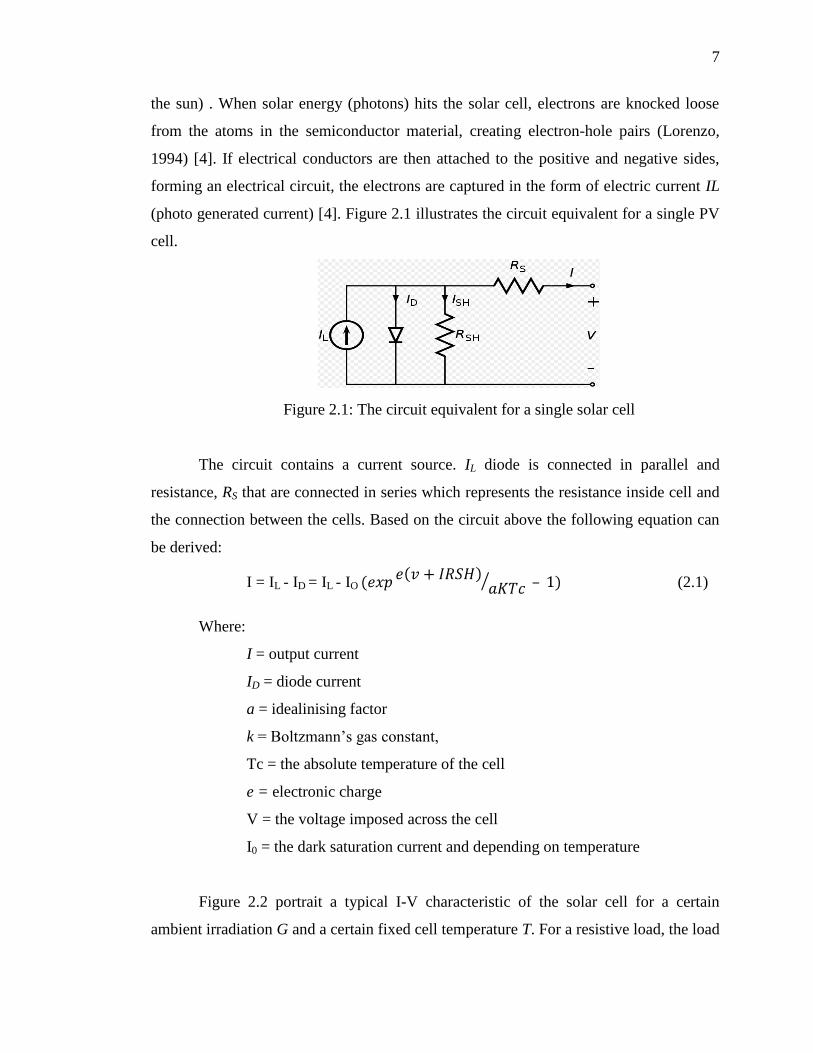
(photo generated current) [4]. Figure 2.1 illustrates the circuit equivalent for a single PV
cell.
Figure 2.1: The circuit equivalent for a single solar cell
The circuit contains a current source. IL diode is connected in parallel and
resistance, RS that are connected in series which represents the resistance inside cell and
the connection between the cells. Based on the circuit above the following equation can
be derived:
I = IL - ID = IL - IO – (2.1)
Where:
I = output current
ID = diode current
a = idealinising factor
k = Boltzmann’s gas constant,
Tc = the absolute temperature of the cell
e = electronic charge
V = the voltage imposed across the cell
I0 = the dark saturation current and depending on temperature
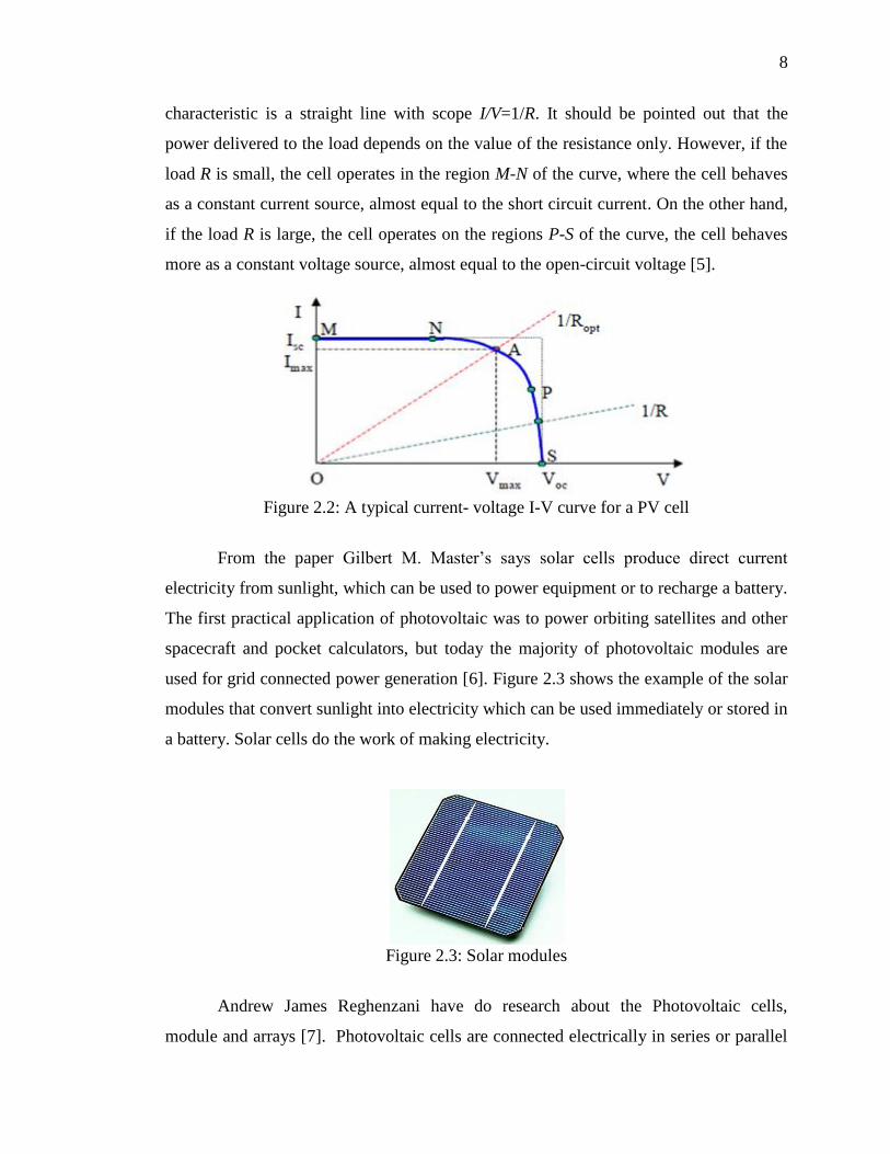
Figure 2.2 portrait a typical I-V characteristic of the solar cell for a certain
ambient irradiation G and a certain fixed cell temperature T. For a resistive load, the load
8
characteristic is a straight line with scope I/V=1/R. It should be pointed out that the
power delivered to the load depends on the value of the resistance only. However, if the
load R is small, the cell operates in the region M-N of the curve, where the cell behaves
as a constant current source, almost equal to the short circuit current. On the other hand,
if the load R is large, the cell operates on the regions P-S of the curve, the cell behaves
more as a constant voltage source, almost equal to the open-circuit voltage [5].
Figure 2.2: A typical current- voltage I-V curve for a PV cell
From the paper Gilbert M. Master’s says solar cells produce direct current
electricity from sunlight, which can be used to power equipment or to recharge a battery.
The first practical application of photovoltaic was to power orbiting satellites and other
spacecraft and pocket calculators, but today the majority of photovoltaic modules are
used for grid connected power generation [6]. Figure 2.3 shows the example of the solar
modules that convert sunlight into electricity which can be used immediately or stored in
a battery. Solar cells do the work of making electricity.
Figure 2.3: Solar modules
Andrew James Reghenzani have do research about the Photovoltaic cells,
module and arrays [7]. Photovoltaic cells are connected electrically in series or parallel

9
circuits to produce higher voltages, currents and power levels. Photovoltaic modules
consist of PV cell circuits sealed in an environmentally protective laminate, and are the
fundamental building blocks of PV systems. Photovoltaic panels include one or more PV
modules assembled as a pre-wired, field-installable unit. A photovoltaic array is the
complete power-generating unit, consisting of any number of PV modules and panels as
shown in Figure 2.4.
Figure 2.4: Transition of cell, module and arrays
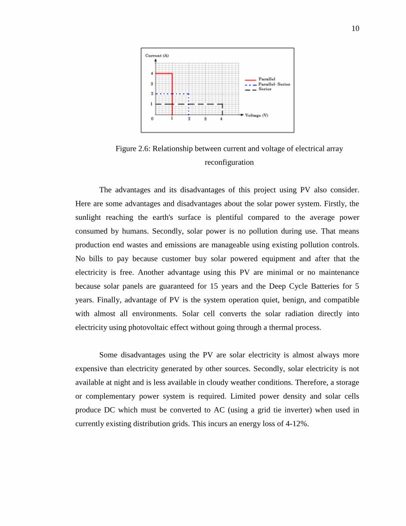
There are three types array of electrical in electrical reconfigurations which are
parallel, parallel-series and series as shown in Figure 2.5. The relationship between
current and voltage of electrical array configuration as shown in Figure 2.6 indicates that
the parallel types provides much current and low voltage, the parallel series provides
moderate current and voltage and the series types provides low current but high
voltage[7].
Figure 2.5: Three types of electrical array
10
Figure 2.6: Relationship between current and voltage of electrical array
reconfiguration
The advantages and its disadvantages of this project using PV also consider.
Here are some advantages and disadvantages about the solar power system. Firstly, the
sunlight reaching the earth's surface is plentiful compared to the average power
consumed by humans. Secondly, solar power is no pollution during use. That means
production end wastes and emissions are manageable using existing pollution controls.
No bills to pay because customer buy solar powered equipment and after that the
electricity is free. Another advantage using this PV are minimal or no maintenance
because solar panels are guaranteed for 15 years and the Deep Cycle Batteries for 5
years. Finally, advantage of PV is the system operation quiet, benign, and compatible
with almost all environments. Solar cell converts the solar radiation directly into
electricity using photovoltaic effect without going through a thermal process.
Some disadvantages using the PV are solar electricity is almost always more
expensive than electricity generated by other sources. Secondly, solar electricity is not
available at night and is less available in cloudy weather conditions. Therefore, a storage
or complementary power system is required. Limited power density and solar cells
produce DC which must be converted to AC (using a grid tie inverter) when used in
currently existing distribution grids. This incurs an energy loss of 4-12%.