Implementation of a 64-Bit Jackson Adder - Harvey...
6
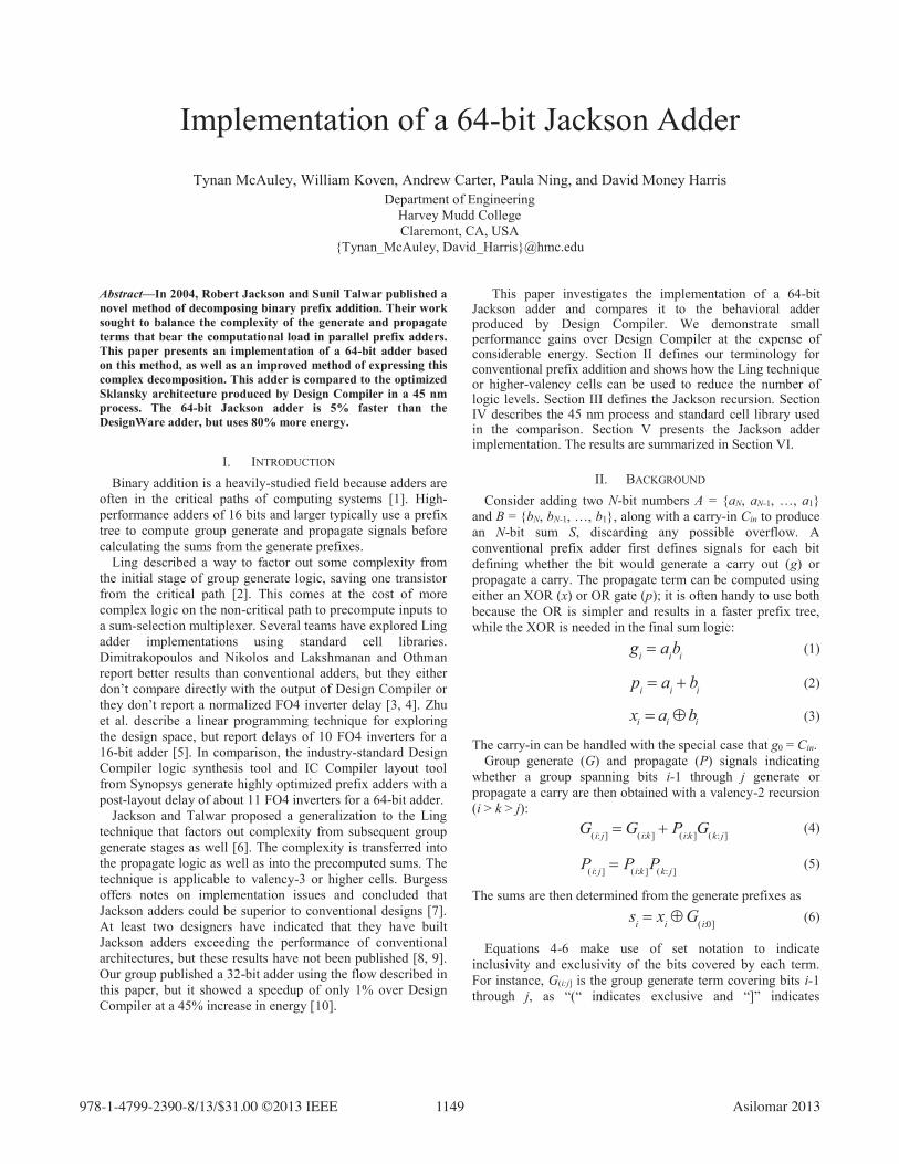
Implementation of a 64-bit Jackson Adder Tynan McAuley, William Koven, Andrew Carter, Paula Ning, and David Money Harris Department of Engineering Harvey Mudd College Claremont, CA, USA {Tynan_McAuley, David_Harris}@hmc.edu Abstract—In 2004, Robert Jackson and Sunil Talwar published a novel method of decomposing binary prefix addition. Their work sought to balance the complexity of the generate and propagate terms that bear the computational load in parallel prefix adders. This paper presents an implementation of a 64-bit adder based on this method, as well as an improved method of expressing this complex decomposition. This adder is compared to the optimized Sklansky architecture produced by Design Compiler in a 45 nm process. The 64-bit Jackson adder is 5% faster than the DesignWare adder, but uses 80% more energy. I. INTRODUCTION Binary addition is a heavily-studied field because adders are often in the critical paths of computing systems [1]. High- performance adders of 16 bits and larger typically use a prefix tree to compute group generate and propagate signals before calculating the sums from the generate prefixes. Ling described a way to factor out some complexity from the initial stage of group generate logic, saving one transistor from the critical path [2]. This comes at the cost of more complex logic on the non-critical path to precompute inputs to a sum-selection multiplexer. Several teams have explored Ling adder implementations using standard cell libraries. Dimitrakopoulos and Nikolos and Lakshmanan and Othman report better results than conventional adders, but they either don’t compare directly with the output of Design Compiler or they don’t report a normalized FO4 inverter delay [3, 4]. Zhu et al. describe a linear programming technique for exploring the design space, but report delays of 10 FO4 inverters for a 16-bit adder [5]. In comparison, the industry-standard Design Compiler logic synthesis tool and IC Compiler layout tool from Synopsys generate highly optimized prefix adders with a post-layout delay of about 11 FO4 inverters for a 64-bit adder. Jackson and Talwar proposed a generalization to the Ling technique that factors out complexity from subsequent group generate stages as well [6]. The complexity is transferred into the propagate logic as well as into the precomputed sums. The technique is applicable to valency-3 or higher cells. Burgess offers notes on implementation issues and concluded that Jackson adders could be superior to conventional designs [7]. At least two designers have indicated that they have built Jackson adders exceeding the performance of conventional architectures, but these results have not been published [8, 9]. Our group published a 32-bit adder using the flow described in this paper, but it showed a speedup of only 1% over Design Compiler at a 45% increase in energy [10]. This paper investigates the implementation of a 64-bit Jackson adder and compares it to the behavioral adder produced by Design Compiler. We demonstrate small performance gains over Design Compiler at the expense of considerable energy. Section II defines our terminology for conventional prefix addition and shows how the Ling technique or higher-valency cells can be used to reduce the number of logic levels. Section III defines the Jackson recursion. Section IV describes the 45 nm process and standard cell library used in the comparison. Section V presents the Jackson adder implementation. The results are summarized in Section VI. II. BACKGROUND Consider adding two N-bit numbers A = {aN, aN-1, …, a1} and B = {bN, bN-1, …, b1}, along with a carry-in Cin to produce an N-bit sum S, discarding any possible overflow. A conventional prefix adder first defines signals for each bit defining whether the bit would generate a carry out (g) or propagate a carry. The propagate term can be computed using either an XOR (x) or OR gate (p); it is often handy to use both because the OR is simpler and results in a faster prefix tree, while the XOR is needed in the final sum logic: g i a i b i (1) p i a i b i (2) i i i x a b (3) The carry-in can be handled with the special case that g0 = Cin. Group generate (G) and propagate (P) signals indicating whether a group spanning bits i-1 through j generate or propagate a carry are then obtained with a valency-2 recursion (i > k > j): G ( i: j ] G ( i :k ] P ( i: k ] G ( k: j ] (4) P ( i : j ] P ( i: k ] P ( k: j ] (5) The sums are then determined from the generate prefixes as s i x i G ( i:0] (6) Equations 4-6 make use of set notation to indicate inclusivity and exclusivity of the bits covered by each term. For instance, G(i:j] is the group generate term covering bits i-1 through j, as “(“ indicates exclusive and “]” indicates ,((( $VLORPDU
Transcript of Implementation of a 64-Bit Jackson Adder - Harvey...
Implementation of a 64-bit Jackson Adder
Tynan McAuley, William Koven, Andrew Carter, Paula Ning, and David Money Harris Department of Engineering
Harvey Mudd College Claremont, CA, USA
{Tynan_McAuley, David_Harris}@hmc.edu
Abstract—In 2004, Robert Jackson and Sunil Talwar published a novel method of decomposing binary prefix addition. Their work sought to balance the complexity of the generate and propagate terms that bear the computational load in parallel prefix adders. This paper presents an implementation of a 64-bit adder based on this method, as well as an improved method of expressing this complex decomposition. This adder is compared to the optimized Sklansky architecture produced by Design Compiler in a 45 nm process. The 64-bit Jackson adder is 5% faster than the DesignWare adder, but uses 80% more energy.
I. INTRODUCTION Binary addition is a heavily-studied field because adders are
often in the critical paths of computing systems [1]. High-performance adders of 16 bits and larger typically use a prefix tree to compute group generate and propagate signals before calculating the sums from the generate prefixes.
Ling described a way to factor out some complexity from the initial stage of group generate logic, saving one transistor from the critical path [2]. This comes at the cost of more complex logic on the non-critical path to precompute inputs to a sum-selection multiplexer. Several teams have explored Ling adder implementations using standard cell libraries. Dimitrakopoulos and Nikolos and Lakshmanan and Othman report better results than conventional adders, but they either don’t compare directly with the output of Design Compiler or they don’t report a normalized FO4 inverter delay [3, 4]. Zhu et al. describe a linear programming technique for exploring the design space, but report delays of 10 FO4 inverters for a 16-bit adder [5]. In comparison, the industry-standard Design Compiler logic synthesis tool and IC Compiler layout tool from Synopsys generate highly optimized prefix adders with a post-layout delay of about 11 FO4 inverters for a 64-bit adder.
Jackson and Talwar proposed a generalization to the Ling technique that factors out complexity from subsequent group generate stages as well [6]. The complexity is transferred into the propagate logic as well as into the precomputed sums. The technique is applicable to valency-3 or higher cells. Burgess offers notes on implementation issues and concluded that Jackson adders could be superior to conventional designs [7]. At least two designers have indicated that they have built Jackson adders exceeding the performance of conventional architectures, but these results have not been published [8, 9]. Our group published a 32-bit adder using the flow described in this paper, but it showed a speedup of only 1% over Design Compiler at a 45% increase in energy [10].
This paper investigates the implementation of a 64-bit Jackson adder and compares it to the behavioral adder produced by Design Compiler. We demonstrate small performance gains over Design Compiler at the expense of considerable energy. Section II defines our terminology for conventional prefix addition and shows how the Ling technique or higher-valency cells can be used to reduce the number of logic levels. Section III defines the Jackson recursion. Section IV describes the 45 nm process and standard cell library used in the comparison. Section V presents the Jackson adder implementation. The results are summarized in Section VI.
II. BACKGROUND Consider adding two N-bit numbers A = {aN, aN-1, …, a1}
and B = {bN, bN-1, …, b1}, along with a carry-in Cin to produce an N-bit sum S, discarding any possible overflow. A conventional prefix adder first defines signals for each bit defining whether the bit would generate a carry out (g) or propagate a carry. The propagate term can be computed using either an XOR (x) or OR gate (p); it is often handy to use both because the OR is simpler and results in a faster prefix tree, while the XOR is needed in the final sum logic:
gi aibi (1)
pi ai � bi (2)
i i ix a b � (3)
The carry-in can be handled with the special case that g0 = Cin. Group generate (G) and propagate (P) signals indicating
whether a group spanning bits i-1 through j generate or propagate a carry are then obtained with a valency-2 recursion (i > k > j):
G(i: j] G( i:k ] � P(i:k ]G(k: j] (4)
P( i: j] P(i:k ]P(k: j] (5)
The sums are then determined from the generate prefixes as si xi �G(i:0] (6)
Equations 4-6 make use of set notation to indicate inclusivity and exclusivity of the bits covered by each term. For instance, G(i:j] is the group generate term covering bits i-1 through j, as “(“ indicates exclusive and “]” indicates
��������������������������������������,((( $VLORPDU�����

inclusive. This notation will be used for the rest of this paper, and will simplify the notation of Jackson recursion.
Many alternatives exist for combining the group generate and propagate signals. Design Compiler generates the modified Sklansky architecture [11] (sometimes called Ladner-Fischer [12]) because it has a minimal number of logic levels and no redundant logic, providing high speed at moderate energy. Fig. 1 shows a 16-bit modified Sklansky adder similar to the one produced by Design Compiler. The top row contains the logic to compute g, p, and x for each bit. The middle of the tree contains the group logic. Note that black cells compute both G and P, while gray cells compute only G for cases where P is unnecessary. The bottom row computes the sums with a final XOR. The design is called modified Sklansky because some of the non-critical P and G signals (such as G(4:0], G(5:0], and G(6:0]) are buffered to reduce the fanout on the critical path.
Fig. 1: 16-bit modified Sklansky tree
One logic level could be removed by directly computing pairwise group generates and propagates G(i+2:i] and P(i+2:i] from the primary inputs a and b. However, the generate logic is overly complex, requiring three series transistors:
G( i�2:i] gi�1 � pi�1gi ai�1bi�1 � ai�1 � bi�1� �aibi
(7)
Ling proposes defining a pseudogenerate signal, H, such that
H( i�1: j] gi �G( i: j] (8)
This is simpler than the conventional generate because it strips out one propagate term:
G(i�1: j] gi � piG( i: j] (9)
G can be recreated from H with an AND gate: G(i�1: j] piH(i�1: j]
(10)
Now the pairwise group pseudogenerate logic is simpler and requires only two series transistors
H( i�2:i] gi�1 � gi ai�1bi�1 � aibi
(11)
Ling also defines a psuedopropagate signal, I, that is a shifted version of the conventional propagate:
I( i: j] P(i�1: j�1] (12)
Now, the valency-2 recursion can be expressed using exactly the same logic as with G and P in EQs (4-5), and can be computed using exactly the same prefix tree:
H( i: j] H( i:k ] � I( i:k ]H(k: j] (13)
I( i: j] I( i:k ]I(k: j] (14)
The sums are computed as si xi �G( i:0]
xi � pi�1H( i:0]
(15)
Because the group pseudogenerates are the critical signal, the sum logic can be refactored to use H to select a sum based on precomputed options using a multiplexer, thus shifting logic off the critical H path:
si H( i:0] ? xi� pi�1ª¬ º¼ : xi (16)
Sparse trees seek to save energy and area by computing the prefixes for every mth bit. Meanwhile, they perform short m-bit ripples to precompute the results for each m-bit block assuming the prefix is 0 and 1. Ling adders naturally benefit from a sparseness of 2 by computing prefixes only in the even-numbered columns (e.g. H(2:0], H(4:0], H(6:0], …, H(14:0]). The sum selection logic now contains a pair of multiplexers as shown in Fig. 2. Note that the a and b inputs may be buffered before computing x, p, and g to reduce the load on the critical path.
H(2k:0] s2ks2k+1
0101
x2kp2k-1x2k+1g2k
Fig. 2: Ling sum selection for sparseness-2
Yet another option for reducing the number of logic levels in an adder is to combine more than two groups at a time in the prefix tree. For example, the valency-3 recursion (i > k > l > j) gives:
G(i: j] G( i:k ] � P(i:k ]G(k:l ] � P( i:k ]P(k:l ]G( l: j] (17)
P( i: j] P(i:k ]P(k:l]P( l: j] (18)
The complexity of these terms is high enough that higher valency adders tend not to be beneficial in static CMOS circuits. Domino gates are more amenable to complex stacks; Hewlett-Packard built very fast domino adders using a valency-4 Ling design [13, 14], but domino has been phased out due to its high power consumption.
����

III. THE JACKSON DECOMPOSTION Jackson and Talwar generalized the Ling technique to
reduce the complexity of the entire prefix tree, rather than just the first stage. The simplification makes higher-valency cells more attractive in static logic. Observe that the valency-3 generate logic is significantly more complex than the propagate logic in EQs (17-18). Jackson defines reduced generate, R, and hyperpropagate, Q, signals that balance these complexities and simplify the worst case. This section reviews the Jackson decomposition using a new notation that we believe is easier to read. First, we must introduce two intermediate signals, D and B.
D(i:j] indicates that the group spanning bits i-1 through j either generate or propagate a carry:
D( i: j] G( i: j] � P( i: j] (19)
Because P(i:j] covers the case of generating in bit j and propagating through the rest, the logic can be simplified to
D( i: j] G( i: j�1] � P(i: j] (20)
and in the common special case of one-bit blocks, D( i�1:i] pi (21)
B(i:j] indicates that the group generates a carry in at least one bit:
B( i: j] gkk j
i�1
� (22)
Now, the group generate signal can be rewritten as
G(i: j] D( i:k ] B(i:k ] �G(k: j]ª¬ º¼ (23)
In other words, the group generates a carry if the upper part either generates or propagates and either at least one bit of the upper part generates (indicating that the upper as a whole generates), or the lower part generates.
The bracketed term is called the reduced generate signal, R: R( i:k: j] B( i:k ] �G(k: j] (24)
It can be viewed as G with the top i-1 through k propagate signals stripped out. The special cases of k = i and k = i-1 correspond to the conventional generate and the Ling pseudogenerate signals, while Jackson adders permit further reductions of k < i-1.
R( i:i: j] G( i: j] (25)
R( i:i�1: j] H( i: j] (26)
The ordinary group generate is recovered from the reduced generate using D; greater reduction of R requires a larger D term. EQ (23) can be rewritten using R as
G(i: j] D( i:k ]R(i:k: j] (27)
Jackson also defines a hyperpropagate signal, Q, to complete the recursion:
Q( i:k: j] P( i:k ]D(k: j] (28)
The frequently used special case of k = j for two-bit groups correspond to the ordinary propagate signal, while k > j produces more complex logic.
Q( i: j: j] P( i: j] (29)
Jackson derives a valency-3 recursion using R and Q, using the indices i > m > n > k > s > t > j:
R( i:k: j] R( i:m:n] � R(n:k:s] �Q(k:s:t]R(s:t: j] (30)
Q( i:k: j] Q(i:m:n]Q(n:k:s] R(k:s:t ] �Q(s:t: j]ª¬ º¼ (31)
As compared to EQs (17-18), these terms are better balanced, and the larger of the two terms is less complicated.
The valency-2 recursion is needed for some of the intermediate terms in a prefix adder. Unfortunately, the recursion is no simpler than the ordinary valency-2 PG logic from EQs (4-5).
R( i:k: j] R( i:k:s] �Q(k:s:t]R(s:t: j] (32)
Q( i:k: j] Q(i:k:s] R(k:s:t ] �Q(s:t: j]ª¬ º¼ (33)
The recursion for D over large groups can be shown to be [10]:
D( i: j] D(i:l] R(i:l:k ] �Q(l:k: j]ª¬ º¼ (34)
The next two sections of this paper describe the first published standard cell implementation of a 64-bit static adder using the Jackson R/Q equations in a 45 nm process.
IV. COMPARISON METHODOLOGY One of the challenges in comparing circuits is to ensure that
the novel circuit is fairly compared to the best known implementation of the conventional circuit [15]. For this reason, we use Synopsys Design Compiler and compare against a synthesized version of a behavioral description, assign y = a + b. We will refer to this as the behavioral adder.
The adders are synthesized onto the ARM standard cell library for a 45 nm partially-depleted SOI process. The library uses regular-Vt transistors and a 12 track cell height (1.68 Pm). It contains a rich set of complex gates including the AOI211 and OAI211 gates used in a valency-3 Jackson recursion. Timing is characterized in the SS corner at 0.9 V, 125 ºC. The fanout-of-4 inverter delay (FO4) is 15.0 ps, corresponding to W = 3.0 ps [1]. A unit-sized (X1) inverter has an input capacitance of 1.6 fF and switching energy of 0.78 fJ. The inputs are driven by an X4 inverter and the outputs are loaded by the capacitance of X4 inverters.
Design Compiler recommends the compile_ultra command for standard high-performance synthesis. To accurately account for routing, the synthesized netlist was passed to Synopsys IC Compiler for placement, routing, and
����

parasitic estimation. The inputs and outputs are constrained to appear in 64 ordered rows with a pitch of one cell per row. Layout utilization is set to 70%, which produces good timing results.
When synthesizing a 64-bit behavioral adder to be as fast as possible, Design Compiler produces the modified Sklansky adder like that of Fig. 1 extended to 64 bits; we will call this a conventional design. The gray cells are built using alternating AOI21 and OAI21 cells according to DeMorgan’s Law. Various gates are cloned to optimize the critical and non-critical paths.
V. IMPLEMENTATION Jackson adders have a huge space of possible architectures
and circuit implementations [7]. High-level architectural decisions—such as setting the valency of each level in the prefix tree as well as the adder’s sparseness—narrowed this design space. A Sklansky architecture for the prefix tree was chosen, starting with a valency-2 Ling first stage. The second and third logic levels used valency-3 gates, taking advantage of Jackson’s more balanced recursion. The final two stages used a mix of valency-2 and 3 gates as needed to compute the final R signals.
This adder has a sparseness of 6 for the lower 60 bits, and then a sparseness of 4 to compute the upper 4 sum bits. This sparseness was chosen to take advantage of the valency-3 Jackson recursion, while balancing complexity between the prefix tree and the carry-select adders, which compute the final sum.
Fig. 3 shows a diagram of the adder, illustrating the signals computed at each logic level. Fig. 4 defines the cells used in the adder. The prefix tree was created by applying EQ (30) and EQ (32) to calculate R prefixes, EQ (31) and EQ (33) for Q prefixes, and EQ (34) for the D prefixes. The computation of the following two prefixes was left out of Fig. 3 to reduce clutter:
Q(9:6:5] (~Q(9:8:7])� (~Q(7:6:5]) (35)
R(42:39:38] (~ R(42:41:40])(~ R(40:39:38]) (36)
These simplifications can be proven by examining EQ (24) and EQ (28). If the G and D terms in each equation are reduced to a single bit, then they can be combined with their adjoining B and P terms, respectively.
Since the adder will be fastest when the R and D paths that help compute the sum are balanced, the width of the final D signal never exceeds 27 bits. A 27-bit D signal is the largest that can be computed in 4 stages of logic using EQ (34). Note that while the final R prefix (~R(60:33:0]) is computed with a valency-3 gate, a valency-2 computation of a final R prefix is also possible. However, this results in slightly worse delay performance due to extra loading of already heavily-loaded signals in the third logic stage.
In parallel with the computation of the D and R prefixes, the carry-select adders at the bottom of Fig. 3 calculate potential sum signals over six bits using a small PG prefix tree, shown
in Fig. 5. Note that while the indices shown range from bits 0 through 5, this design can be applied to any 6-bit range, so long as the appropriate R and D prefixes are used as select signals. By using the R and D signals as selects for multiplexers at the very bottom of the carry-select adders, these signals can be the critical path in the adder while not incurring a large extra delay through the carry-select adders. While Fig. 5 shows the diagram for the 6-bit carry-select adder, the 4-bit carry-select adder in Fig. 3 is constructed by truncating the logic associated with the top two bits in Fig. 5.
VI. RESULTS Table 1 summarizes the post-layout delay, energy, and area
results for the architectures considered.
Table 1: Comparison of 64-bit adder results Behavioral Behavioral Jackson Compiler Option
-ultra -ultra -inc
-inc
Delay (ps) 166.6 165.3 156.8 Energy (fJ) 1663 1641 2959 Area (μm2) 1253 1232 2066
The behavioral adder results are quite good and took months of design refinements to beat. The behavioral adder synthesized with Design Compiler Ultra achieved 11.1 FO4 delays including layout parasitic. Applying incremental resynthesis sped up the design by 0.8% and decreases energy and area by 1.5%. The Jackson adder offers a further 5.1% speedup at a cost of 80% more energy relative to the fastest behavioral adder. The Jackson adder had to be specified as a structural netlist; Design Compiler was unable to achieve such good results with a more abstract description such as Boolean equations. Moreover, the Jackson adder required initial sizing in the structural netlist to achieve good results, and the energy use in Table 1 was only arrived at by brute-force downsizing gates in the adder to determine if they had any effect on the critical path length.
VII. CONCLUSION Design Compiler is the industry standard logic synthesis
tool. The quality of the arithmetic circuits it generates is now very high. This paper has investigated applying the Jackson technique to produce even faster adders.
This paper has presented the first published implementation of a 64-bit Jackson adder with all details shown. The adder also uses a sparseness-6 modified Sklansky tree with a mix of valency-2 and valency-3 stages to minimize logic levels. The synthesis results are 5% faster than the behavioral adder but consume significantly more energy.
Ideas for future work include optimizing this adder for energy. The adder was carefully designed for delay but not tuned for energy; potential remains to reduce the energy by optimizing noncritical paths.
ACKNOWLEDGMENT
����

This work was supported by the Clay-Wolkin Fellowship at Harvey Mudd College.
REFERENCES [1] N. Weste and D. Harris, CMOS VLSI Design, 4th ed., Boston, MA:
Addison Wesley, 2011. [2] H. Ling, “High-speed binary adder,” IBM J. Research and Dev., vol. 25,
no. 3, May 1981, pp. 156-166. [3] G. Dimitrakopoulos and D. Nikolos, “High-speed parallel-prefix VLSI
Ling adders,” IEEE Trans. Computers, vol. 54, no. 2, Feb. 2005, pp. 225-231.
[4] A Lakshmanan and M. Othman, “High-speed hybrid parallel-prefix carry-select adder using Ling’s algorithm,” Intl. Conf. Semiconductor Electronics, 2006, pp. 598-602.
[5] Y. Zhu, J. Liu, H. Zhu, and C.K. Cheng, “Timing-power optimization for mixed-radix Ling adders,” Asia/South Pacific Design Automation Conf., 2008, pp. 131-137.
[6] R. Jackson and S. Talwar, “High speed binary addition,” Proc. Asilomar Conf. Signals, Systems, and Computers, Nov. 2004, pp. 1350-1353.
[7] N. Burgess, “Implementation of recursive Ling adders in CMOS VLSI,” Proc. Asilomar Conf. Signals, Systems, and Computers, 2009.
[8] R. Jackson, personal communication, 5 July 2010. [9] E. Mahurin, personal communication, 25 October 2010. [10] M. Keeter, D. Harris, A. Macrae, R. Glick, and M. Ong,
“Implementation of 32-bit Ling and Jackson Adders,” Proc. Asilomar Conf. Signals, Systems, and Computers, 2011.
[11] J. Sklansky, “Conditional-sum addition logic,” IRE Trans. Electronic Computers, vol. EC-9, Jun. 1960, pp. 226-231.
[12] R. Ladner and M. Fischer, “Parallel prefix computation,” J. ACM, vol. 27, no. 4, Oct. 1980, pp. 831-838.
[13] S. Naffziger, “A subnanosecond 0.5 Pm 64b adder design,” Proc. IEEE Intl. Solid-State Circuits Conf., 1996, pp. 362-363.
[14] S. Naffziger, “High speed addition using Ling’s equations and dynamic CMOS logic,” US Patent 5,719,803, 1998.
[15] R. Zimmermann and W. Fichtner, “Low-power logic styles: CMOS versus pass-transistor logic,” IEEE J. Solid-State Circuits, vol. 32, no. 7, July 1997, pp. 1079-1090.
Figure 4: Cell designs for Jackson adder
Figure 5: Cell design for 6-bit carry-select adder
����

Figure 3: 64-bit Jackson Adder
����