IMPLEMENTATION AND CIRCUIT MINIMIZATION, ASSIGNMENT ... · PDF fileMINIMIZATION, ASSIGNMENT...
46
Chapter 15 SEQUENTIAL CIRCUITS — ANALYSIS, STATE- MINIMIZATION, ASSIGNMENT AND CIRCUIT IMPLEMENTATION
Transcript of IMPLEMENTATION AND CIRCUIT MINIMIZATION, ASSIGNMENT ... · PDF fileMINIMIZATION, ASSIGNMENT...
Chapter 15
SEQUENTIAL CIRCUITS —ANALYSIS, STATE-
MINIMIZATION, ASSIGNMENT AND CIRCUIT
IMPLEMENTATION
Ch15L2- "Digital Principles and Design", Raj Kamal, Pearson Education, 2006 2
Lesson 2
ANALYSIS OF CLOCKED SEQUENTIAL CIRCUIT

Ch15L2- "Digital Principles and Design", Raj Kamal, Pearson Education, 2006 3
Outline
• Procedure• Excitation table• Transition table• State table • State Diagram
Ch15L2- "Digital Principles and Design", Raj Kamal, Pearson Education, 2006 4
Analysis Procedure — Clocked Sequential circuit
• 1. Draw logic circuit diagram• 2. Perform state variable assignments and
excitation variable(means FF inputs) assignments
• 3. Find the expressions for excitations from flip-flop characteristic equations as per the excitations variables and make an excitation table. [Find Q’ = FQ (X, Q) and Y.]
Ch15L2- "Digital Principles and Design", Raj Kamal, Pearson Education, 2006 5
Analysis Procedure• 4. Make transition table from the
expressions for Y = Fo (X, Q) in case of Mealy model and Y = Fo (X) in case of Moore model.
• 5. Perform state minimization and make minimal state table.
• 6. Draw the state diagram.

Ch15L2- "Digital Principles and Design", Raj Kamal, Pearson Education, 2006 6
Outline
• Procedure• Excitation table• Transition table• State table • State Diagram

Ch15L2- "Digital Principles and Design", Raj Kamal, Pearson Education, 2006 7
Excitation table
• Tabular representation of X and Q at the FFs and of Y as per FQ for the combination circuit at the output stages.
• Gives present states and the inputs given at the memory section.
• Gives the memory-section outputs that follow the excitations

Ch15L2- "Digital Principles and Design", Raj Kamal, Pearson Education, 2006 8
Excitation Table for Y = X. Q2 +Q1; Q1’ =D and Q2’ = Qn+1 = J. Q n + K. Q n
State Excitation Inputs Y (Q1,Q2) [D, (J, K)]X=0 [D, (J, K)]X=1 X=0 X =1
�Y is present output state after the X inputs but before transition
(0, 0) 0, (0, 0) 1, (0,1) 0 0
(0, 1) 0, (0, 0) 1, (0,1) 1 0(1, 0) 0, (1, 0) 1, (1,1) 1 1
(1, 1) 0, (1, 0) 1, (1,1) 1 1

Ch15L2- "Digital Principles and Design", Raj Kamal, Pearson Education, 2006 9
Excitation Table Rows• Number of rows in each column equals 2 m
where m is the number of flip-flops because each flip-flop has one Q output and m flip-flops will have 2m different combinations of the states at the Qs.
• For example, if (Q1, Q2) are the Qs of two FFs, then (Q1, Q2) = (0, 0), (0, 1), (1, 0) and (1, 1) are the four combinations possible for the four different states of the memory section present outputs

Ch15L2- "Digital Principles and Design", Raj Kamal, Pearson Education, 2006 10
Excitation Table Columns• First column—present state (Q1, Q2) in its
each row• The number of columns for the excitation
inputs Q’ equals the number of possible combinations of external inputs in the set X. It equals 2i if there are i distinct literal to represent the inputs when there are i inputs X0, X1, … Xi–1. If i = 1, then columns 2 and 3 will be for X = 0 and X =1, as there are two possible values of X.
Ch15L2- "Digital Principles and Design", Raj Kamal, Pearson Education, 2006 11
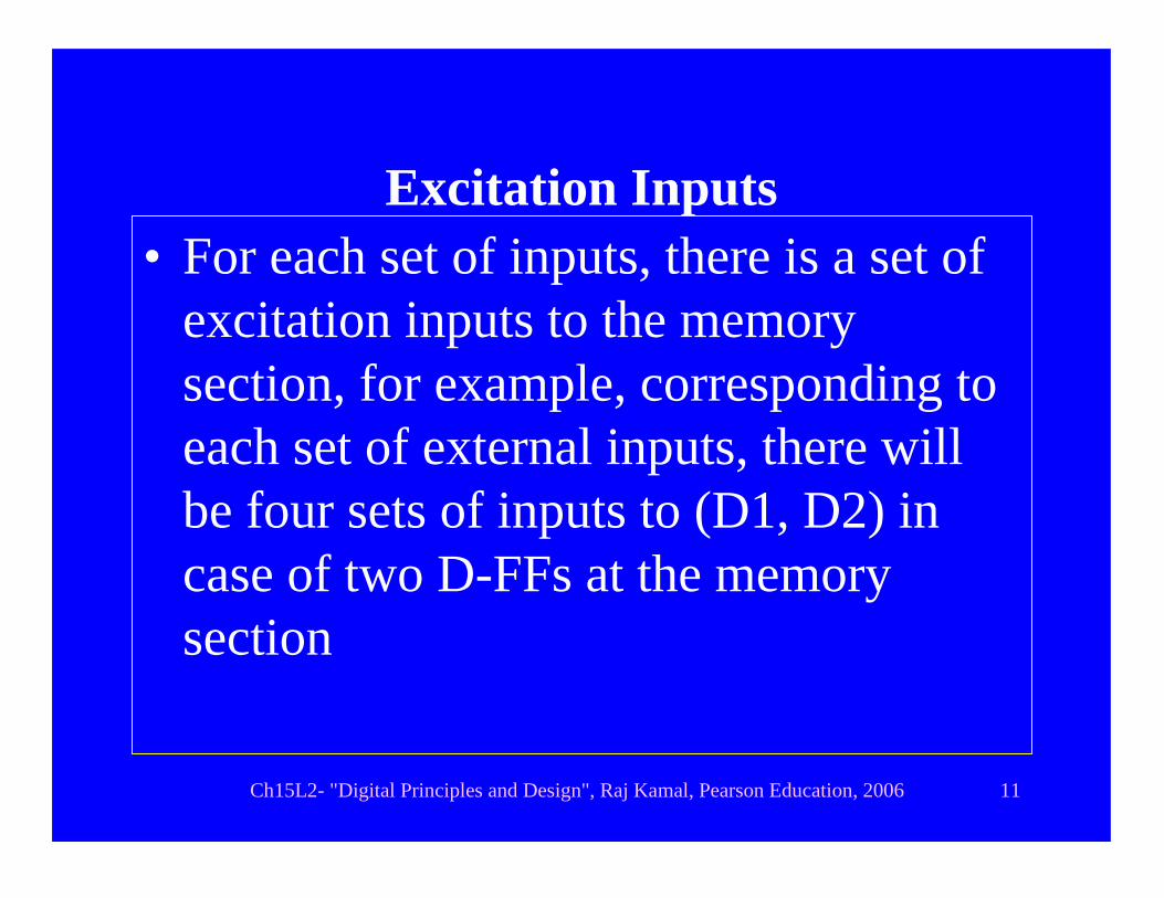
Excitation Inputs • For each set of inputs, there is a set of
excitation inputs to the memory section, for example, corresponding to each set of external inputs, there will be four sets of inputs to (D1, D2) in case of two D-FFs at the memory section
Ch15L2- "Digital Principles and Design", Raj Kamal, Pearson Education, 2006 12
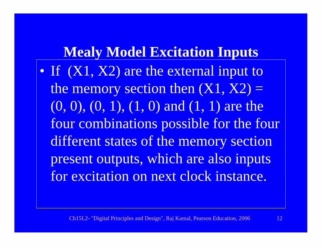
Mealy Model Excitation Inputs • If (X1, X2) are the external input to
the memory section then (X1, X2) = (0, 0), (0, 1), (1, 0) and (1, 1) are the four combinations possible for the four different states of the memory section present outputs, which are also inputs for excitation on next clock instance.

Ch15L2- "Digital Principles and Design", Raj Kamal, Pearson Education, 2006 13
Moore Model Excitation Inputs
• The number of column = 1 for a set of Q inputs Q as in Moore model Q’depends on Qs only.
Ch15L2- "Digital Principles and Design", Raj Kamal, Pearson Education, 2006 14
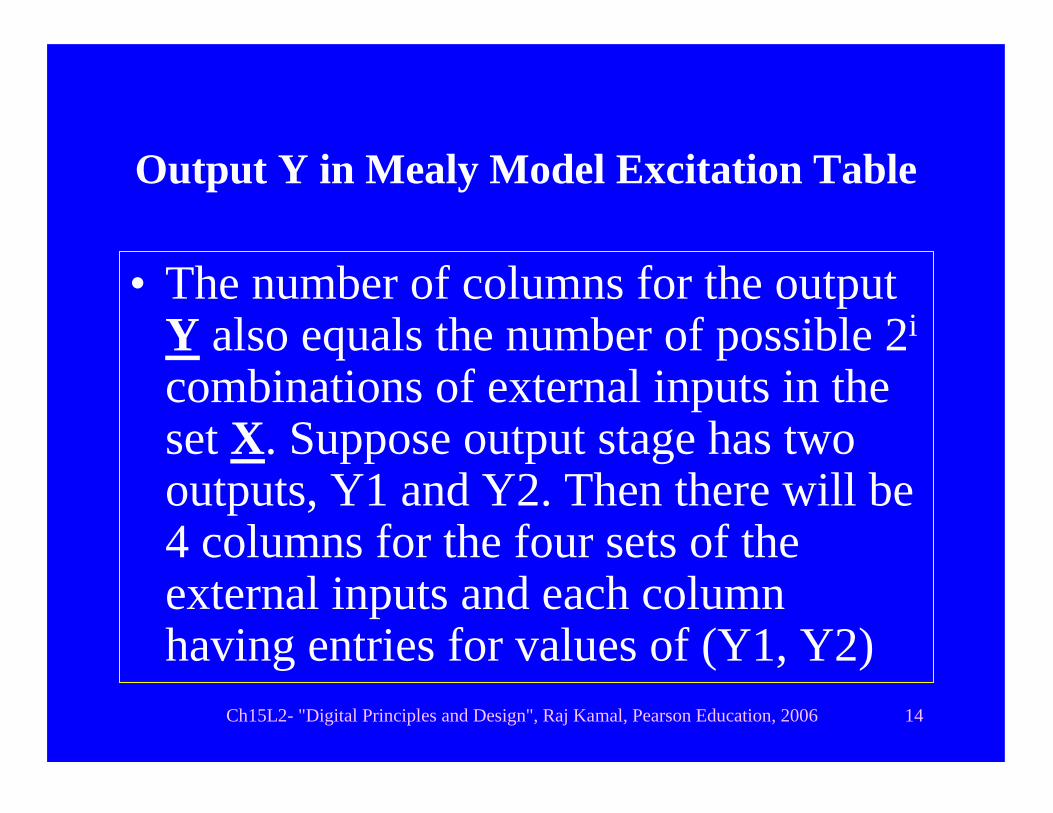
Output Y in Mealy Model Excitation Table
• The number of columns for the output Y also equals the number of possible 2i
combinations of external inputs in the set X. Suppose output stage has two outputs, Y1 and Y2. Then there will be 4 columns for the four sets of the external inputs and each column having entries for values of (Y1, Y2)

Ch15L2- "Digital Principles and Design", Raj Kamal, Pearson Education, 2006 15
Moore Model Excitation Table
• The number of column = 1 for the output Y as in Moore model Y depends on Qs only. The column entries for values of (Y1, Y2) as per the combinational circuit between the memory section output Qs and Ys

Ch15L2- "Digital Principles and Design", Raj Kamal, Pearson Education, 2006 16
Outline
• Procedure• Excitation table• Transition table• State table • State Diagram

Ch15L2- "Digital Principles and Design", Raj Kamal, Pearson Education, 2006 17
Transition table
• A tabular representation of FQ and Fo.• It shows how the sequential circuit FF
will respond to all the present inputs Xs and Qs and will generate Ys from the Q’s.

Ch15L2- "Digital Principles and Design", Raj Kamal, Pearson Education, 2006 18
Transition Table for Y = X. Q2 +Q1; Q1’ =D and Q2’ = Qn+1 = J. Q n + K. Q n
State Transition Outputs Y (Q1,Q2) [Q1’,Q2’]X=0 [Q1’,Q2’]X=1 X=0 X =1
�Y is present output state after the X inputs but before transition
(0, 0) 0, 0 1, 0 0 0
(0, 1) 0, 1 1, 0 1 0(1, 0) 0, 1 1, 1 1 1
(1, 1) 0, 1 0, 0 1 1

Ch15L2- "Digital Principles and Design", Raj Kamal, Pearson Education, 2006 19
Transition Table Rows• Number of rows in each column equals 2 m
where m is the number of flip-flops because each flip-flop has one Q output and m flip-flops will have 2m different combinations of the states at the Qs.
• For example, if (Q1, Q2) are the Qs of two FFs, then (Q1, Q2) = (0, 0), (0, 1), (1, 0) and (1, 1) are the four combinations possible for the four different states of the memory section present outputs
Ch15L2- "Digital Principles and Design", Raj Kamal, Pearson Education, 2006 20
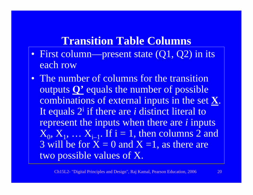
Transition Table Columns• First column—present state (Q1, Q2) in its
each row• The number of columns for the transition
outputs Q’ equals the number of possible combinations of external inputs in the set X. It equals 2i if there are i distinct literal to represent the inputs when there are i inputs X0, X1, … Xi–1. If i = 1, then columns 2 and 3 will be for X = 0 and X =1, as there are two possible values of X.
Ch15L2- "Digital Principles and Design", Raj Kamal, Pearson Education, 2006 21
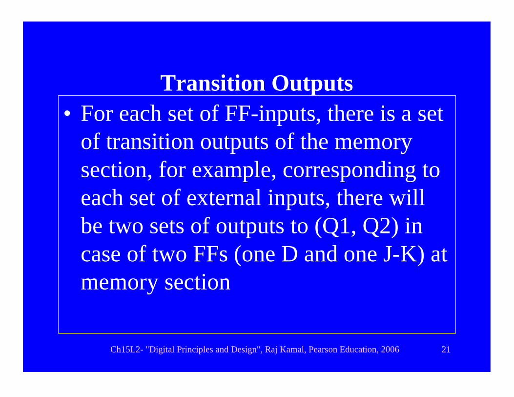
Transition Outputs • For each set of FF-inputs, there is a set
of transition outputs of the memory section, for example, corresponding to each set of external inputs, there will be two sets of outputs to (Q1, Q2) in case of two FFs (one D and one J-K) at memory section
Ch15L2- "Digital Principles and Design", Raj Kamal, Pearson Education, 2006 22
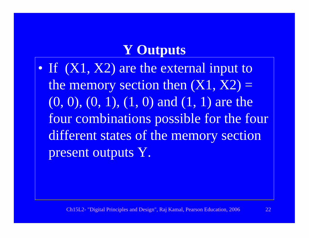
Y Outputs • If (X1, X2) are the external input to
the memory section then (X1, X2) = (0, 0), (0, 1), (1, 0) and (1, 1) are the four combinations possible for the four different states of the memory section present outputs Y.
Ch15L2- "Digital Principles and Design", Raj Kamal, Pearson Education, 2006 23
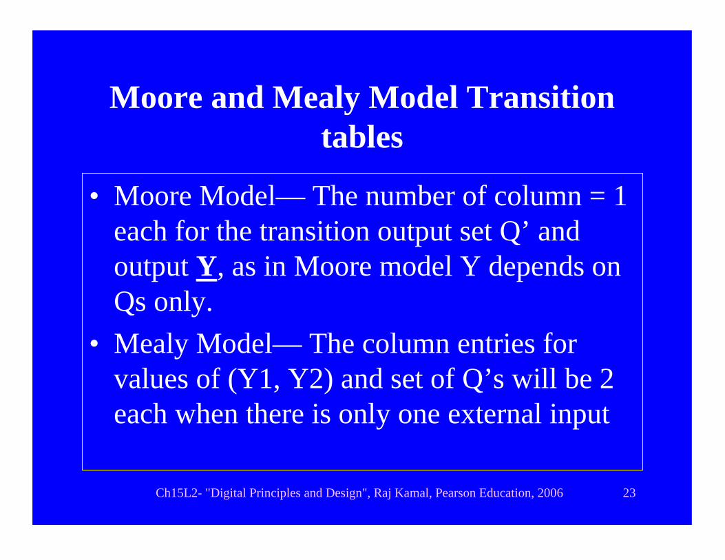
Moore and Mealy Model Transition tables
• Moore Model— The number of column = 1 each for the transition output set Q’ and output Y, as in Moore model Y depends on Qs only.
• Mealy Model— The column entries for values of (Y1, Y2) and set of Q’s will be 2 each when there is only one external input

Ch15L2- "Digital Principles and Design", Raj Kamal, Pearson Education, 2006 24
Outline
• Procedure• Excitation table• Transition table• State table • State Diagram

Ch15L2- "Digital Principles and Design", Raj Kamal, Pearson Education, 2006 25
State Table • State table can made easily• A set of present Q0, Q1,.. denotes a state• Each set assigned a state-name Si as
follows:• (Q1, Q2) = (0,0) → S0• (Q1, Q2) = (0,1) → S1• (Q1, Q2) = (0,0) → S2• (Q1, Q2) = (0,0) → S3

Ch15L2- "Digital Principles and Design", Raj Kamal, Pearson Education, 2006 26
State table
1. Tabular representation of Q,’Q’ at given Y in terms of S0, S1, S2, ...states assigned to the sets of the Qs at FFs
2. Gives in terms of S0, S1, S2, ...the memory-section outputs that follow the state transitions after excitation inputs

Ch15L2- "Digital Principles and Design", Raj Kamal, Pearson Education, 2006 27
State Table for Y = X. Q2 +Q1; Q1’ =D and Q2’ = Qn+1 = J. Q n + K. Q n
State Next State Outputs Y (Q1,Q2) [Q1, Q2]X=0 [Q1, Q2]X=1 X=0 X =1
�Y is present output state after the X inputs but before transition
S0 S0 S2 0 0
S1 S1 S2 1 0S2 S1 S3 1 1
S3 S1 S0 1 1
Ch15L2- "Digital Principles and Design", Raj Kamal, Pearson Education, 2006 28
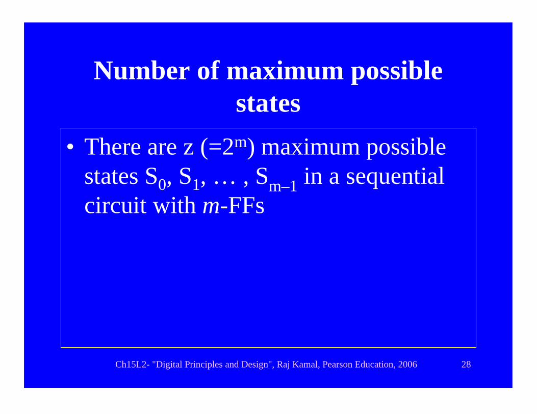
Number of maximum possible states
• There are z (=2m) maximum possible states S0, S1, … , Sm–1 in a sequential circuit with m-FFs

Ch15L2- "Digital Principles and Design", Raj Kamal, Pearson Education, 2006 29
State Table Rows• Number of row in state table = z , one
row for each state • For m = 2 , rows are for S0, S1, S2 and
S3, each corresponding to a state of the circuit.
Ch15L2- "Digital Principles and Design", Raj Kamal, Pearson Education, 2006 30
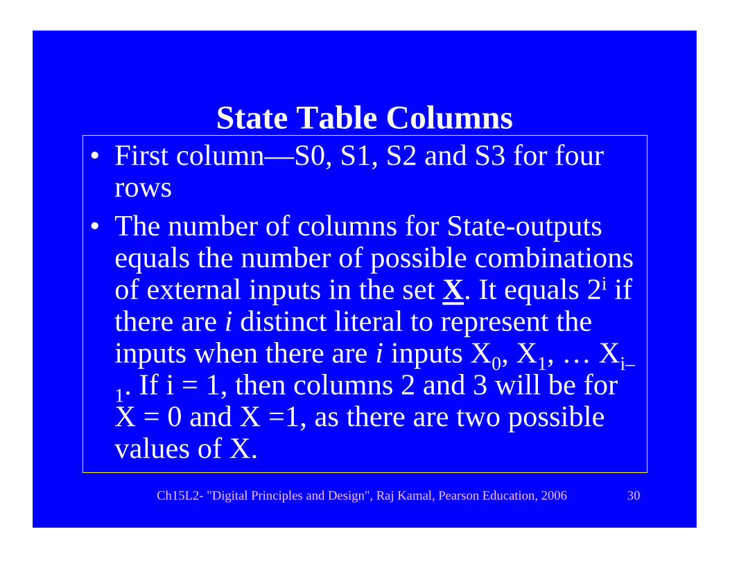
State Table Columns• First column—S0, S1, S2 and S3 for four
rows• The number of columns for State-outputs
equals the number of possible combinations of external inputs in the set X. It equals 2i if there are i distinct literal to represent the inputs when there are i inputs X0, X1, … Xi–
1. If i = 1, then columns 2 and 3 will be for X = 0 and X =1, as there are two possible values of X.

Ch15L2- "Digital Principles and Design", Raj Kamal, Pearson Education, 2006 31
Number of Y Output columns
• Same as number of columns for next state before
Ch15L2- "Digital Principles and Design", Raj Kamal, Pearson Education, 2006 32
State minimization from state table
• We shall learn it in next lesson
Ch15L2- "Digital Principles and Design", Raj Kamal, Pearson Education, 2006 33
Outline
• Procedure• Excitation table• Transition table• State table • State Diagram

Ch15L2- "Digital Principles and Design", Raj Kamal, Pearson Education, 2006 34
State Diagram
• A set of present Q0, Q1,.. is denoted by a state. A state diagram is a diagrammatic representation of state table to show the transitions from present state to next state.
• A state diagram is drawn after state minimization at the state table

Ch15L2- "Digital Principles and Design", Raj Kamal, Pearson Education, 2006 35
Number of Nodes
• A circle shows a node• The number of nodes = number of
rows in the state table.• For two flip-flops, there are four states
S1, S2, S3 and S4. So four circles are drawn for the four nodes

Ch15L2- "Digital Principles and Design", Raj Kamal, Pearson Education, 2006 36
Directed Arc
• A directed arc from the present state node to the next state node shows a transition

Ch15L2- "Digital Principles and Design", Raj Kamal, Pearson Education, 2006 37
Directed arcs to next state
• A small diameter directed circular arc, which starts from node and ends at the same node represents a transition in which the state remains unchanged [Si remains Si]
• The number of directed circular arcs equals the number of transitions in which the state does not change
Ch15L2- "Digital Principles and Design", Raj Kamal, Pearson Education, 2006 38
Directed arcs to next state
• A small diameter directed arc, which starts from node and ends at another node represents a transition in which the state changed [Si becomes Sj]
• The number of directed arcs to another node equals the number of transitions in which the state changes

Ch15L2- "Digital Principles and Design", Raj Kamal, Pearson Education, 2006 39
Mealy Model state diagram
• Each state S0 or S1, ... is labeled as S0or S1 at the center of circle, which is representing the node
• Each arc or circular arc is labeled as X/Y [present input X and output Y].
Ch15L2- "Digital Principles and Design", Raj Kamal, Pearson Education, 2006 40
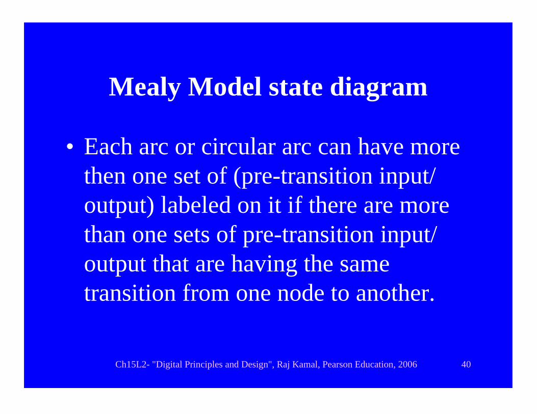
Mealy Model state diagram
• Each arc or circular arc can have more then one set of (pre-transition input/ output) labeled on it if there are more than one sets of pre-transition input/ output that are having the same transition from one node to another.
Ch15L2- "Digital Principles and Design", Raj Kamal, Pearson Education, 2006 41
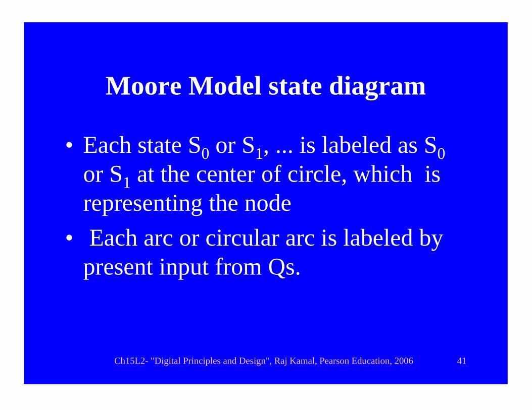
Moore Model state diagram
• Each state S0 or S1, ... is labeled as S0or S1 at the center of circle, which is representing the node
• Each arc or circular arc is labeled by present input from Qs.
Ch15L2- "Digital Principles and Design", Raj Kamal, Pearson Education, 2006 42
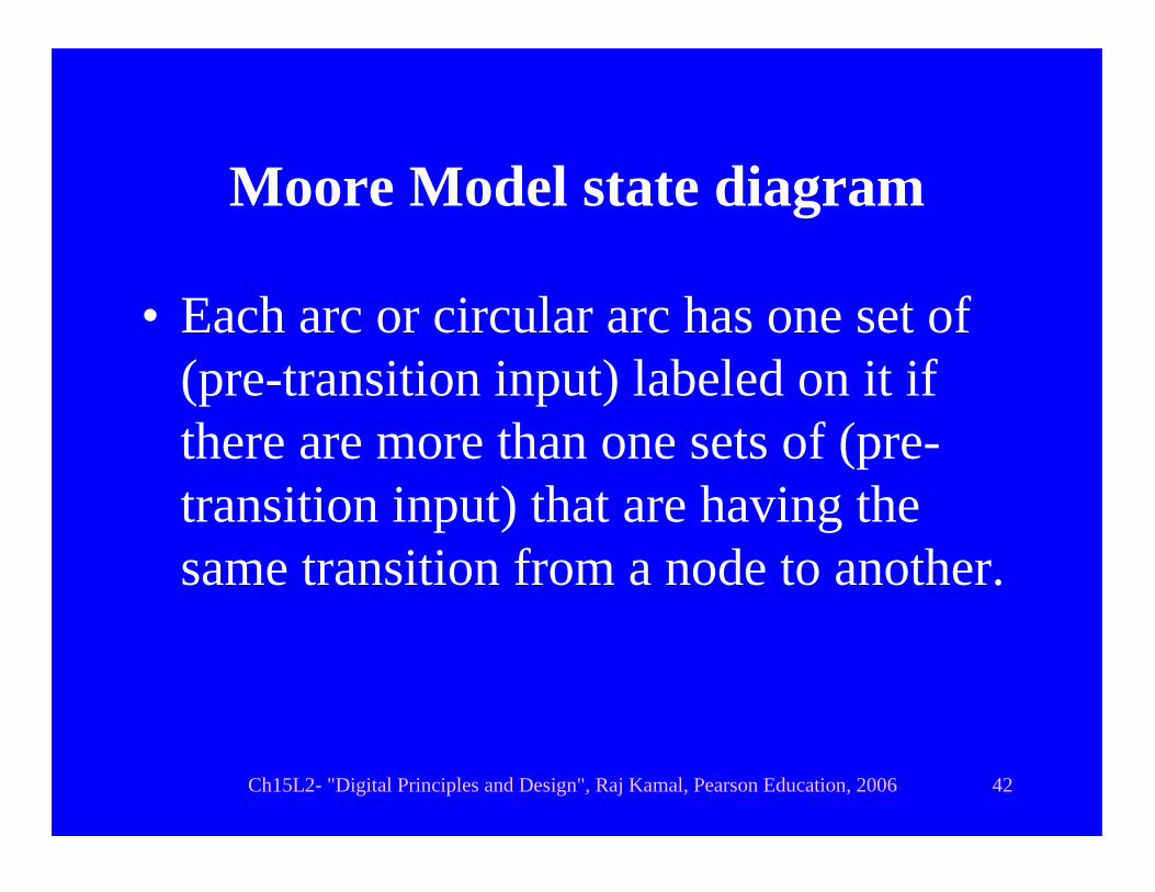
Moore Model state diagram
• Each arc or circular arc has one set of (pre-transition input) labeled on it if there are more than one sets of (pre-transition input) that are having the same transition from a node to another.

Summary

• Analysis of logic clocked sequential circuit is in steps:
• Making excitation table• Making state transition table • Making State table • Reducing the table after a state
minimization process • Draw state diagram using circles and
directed arcs

End of Lesson 2 on ANALYSIS OF CLOCKED SEQUENTIAL CIRCUIT
Ch15L2- "Digital Principles and Design", Raj Kamal, Pearson Education, 2006 46
THANK YOU


![Installation Guide for the Circuit Wall Enhancement/ Replacement Kit · PDF file · 2012-09-11[Type text] Installation Guide for the "Circuit Wall" Enhancement/ Replacement Kit for](https://static.fdocuments.in/doc/165x107/5ab492f17f8b9a156d8c0be8/installation-guide-for-the-circuit-wall-enhancement-replacement-kit-type-text.jpg)