Impacts of Centrally and Non-centrally Planned Distributed ... · PDF fileImpacts of Centrally...
7
International Journal of Smart Grid and Clean Energy Impacts of Centrally and Non-centrally Planned Distributed Generation on Low Voltage Distribution Network Jun Huat Tang*, Yun Seng Lim, Stella Morris, Jianhui Wong a Faculty of Engineering and Science, Universiti Tunku Abdul Rahman, Jalan Genting Klang 53300 Kuala Lumpur, Malaysia Abstract The introduction of Feed in Tariff (FiT) by Malaysian Government in December 2011 has resulted in the increasing number of distributed generators (DG) connected to the existing radial low voltage (LV) distribution network. It is important to investigate the technical issues caused by anticipated amount of DG, in order to ensure the safety, reliability, and efficiency of the power system. The paper describes a simulation work based on a commercial and residential LV distribution network in the state of Selangor. Both centrally and non-centrally planned distributed generators are studied to investigate the positive and negative impacts of DG connected to the LV distribution network. The voltage unbalance factor in LV distribution network with different penetration level of DG is studied. In addition, the LV network with DGs is also used to minimize the network power losses. The power factor and the voltage unbalance factor at point of coupling are studied. Finally, this simulation work is extended to assess how the cable length from substation to the point of coupling affects the voltage unbalance in the network. Keywords: Voltage unbalanced factor, distributed generation, low voltage distribution network 1. Introduction The emergence of green technology plays a very influential role, including Malaysia with the vast potential it presents environmentally and economically. The Malaysian Government has committed to the reduction of greenhouse gas (GHG) emission by 40 per cent in 2020 at the Copenhagen meeting on climate change held in 2009. This has led to high investment on the renewable energy by the government, government linked companies (GLC) and private sectors [1]. Grid-tied Photovoltaic (PV) systems are driven by the financial incentive programs administered by the Malaysia Building Integrated Photovoltaic (MBIPV) Project. It is expected that by the end of 10 th Plan in 2020, Malaysia should have installed more than 3,000MW of new renewable energy sources due to the proposed feed-in tariff (FiT) [2],[3]. The energy demand forecast has increased from 15,000MW in 2010 to 25,000MW by 2030 [4]. In order to meet the increasing electricity demand, capital intensive power system infrastructure will need to be continuously developed. However, the existing radial LV distribution networks are designed in such a way as to allow unidirectional power flow. In addition, a radial network normally operates with a single source feeding downstream load without any other distributed generation. Consequently, the low voltage (LV) distribution networks with a high penetration of distributed generator (DG) may cause numerous technical issues affecting the stability of the power system. These technical issues include network adequacy, power quality, protection schemes, network losses, stability and interface design [5]. The development of clean energy is crucial as the earth could not afford to allow emerging economies to follow the same “grow first, clean later” model adopted before, as it would bring grave consequences to the well-being and security of future generation. In the past, research and study have been focus on the connection of DG on the medium voltage * Manuscript received June 9, 2012; revised August 18, 2012. Corresponding author. Tel.: +60-168563225; E-mail address: [email protected].
Transcript of Impacts of Centrally and Non-centrally Planned Distributed ... · PDF fileImpacts of Centrally...
International Journal of Smart Grid and Clean Energy
Impacts of Centrally and Non-centrally Planned Distributed Generation on Low Voltage Distribution Network
Jun Huat Tang*, Yun Seng Lim, Stella Morris, Jianhui Wonga
Faculty of Engineering and Science, Universiti Tunku Abdul Rahman, Jalan Genting Klang 53300 Kuala Lumpur, Malaysia
Abstract
The introduction of Feed in Tariff (FiT) by Malaysian Government in December 2011 has resulted in the increasing number of distributed generators (DG) connected to the existing radial low voltage (LV) distribution network. It is important to investigate the technical issues caused by anticipated amount of DG, in order to ensure the safety, reliability, and efficiency of the power system. The paper describes a simulation work based on a commercial and residential LV distribution network in the state of Selangor. Both centrally and non-centrally planned distributed generators are studied to investigate the positive and negative impacts of DG connected to the LV distribution network. The voltage unbalance factor in LV distribution network with different penetration level of DG is studied. In addition, the LV network with DGs is also used to minimize the network power losses. The power factor and the voltage unbalance factor at point of coupling are studied. Finally, this simulation work is extended to assess how the cable length from substation to the point of coupling affects the voltage unbalance in the network. Keywords: Voltage unbalanced factor, distributed generation, low voltage distribution network
1. Introduction
The emergence of green technology plays a very influential role, including Malaysia with the vast potential it presents environmentally and economically. The Malaysian Government has committed to the reduction of greenhouse gas (GHG) emission by 40 per cent in 2020 at the Copenhagen meeting on climate change held in 2009. This has led to high investment on the renewable energy by the government, government linked companies (GLC) and private sectors [1]. Grid-tied Photovoltaic (PV) systems are driven by the financial incentive programs administered by the Malaysia Building Integrated Photovoltaic (MBIPV) Project. It is expected that by the end of 10th Plan in 2020, Malaysia should have installed more than 3,000MW of new renewable energy sources due to the proposed feed-in tariff (FiT) [2],[3].
The energy demand forecast has increased from 15,000MW in 2010 to 25,000MW by 2030 [4]. In order to meet the increasing electricity demand, capital intensive power system infrastructure will need to be continuously developed. However, the existing radial LV distribution networks are designed in such a way as to allow unidirectional power flow. In addition, a radial network normally operates with a single source feeding downstream load without any other distributed generation. Consequently, the low voltage (LV) distribution networks with a high penetration of distributed generator (DG) may cause numerous technical issues affecting the stability of the power system. These technical issues include network adequacy, power quality, protection schemes, network losses, stability and interface design [5]. The development of clean energy is crucial as the earth could not afford to allow emerging economies to follow the same “grow first, clean later” model adopted before, as it would bring grave consequences to the well-being and security of future generation.
In the past, research and study have been focus on the connection of DG on the medium voltage
* Manuscript received June 9, 2012; revised August 18, 2012. Corresponding author. Tel.: +60-168563225; E-mail address: [email protected].
Jun Huat Tang et al.: Impacts of Centrally and Non-centrally Planned Distributed Generation … 61
network without neutral line and balanced operation is assumed [6]-[8]. Under the FiT, commercial and residential customers can directly inject single phase DG power into the 3 phase 4 wire LV distribution network. The network voltage unbalance factor and power losses in the LV network with DG were studied [9]-[11]. This paper further study how the power factor at the DG point of coupling (PoC) and cable length affect the voltage unbalance factor in the network.
The paper is arranged in the following manner. Section 2 describes the modeling approach, the details of the LV distribution network. The results of the simulation studies are discussed in Section 3. Section 4 presents the conclusion of the studies.
2. Modeling Approach
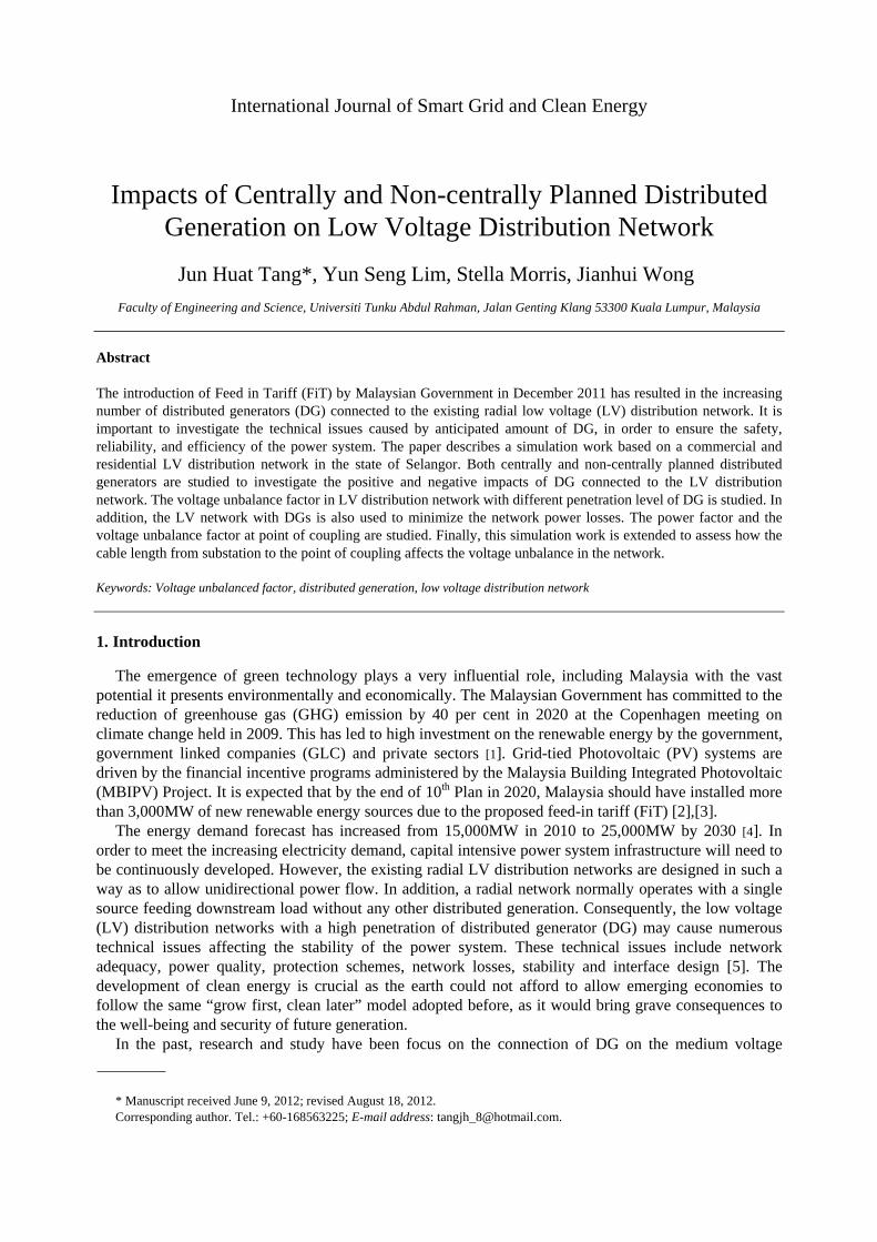
Two LV networks are used in this research. Fig. 1 (a) and Fig. 1 (b) represent a commercial LV network and a residential LV network of Petaling Jaya, respectively. These LV network using are modelled using DIgSILENT PowerFactory. DIgSILENT PowerFactory is the most economical solution, as data handling, modelling capabilities and overall functionality replace a set of other software systems, thereby minimizing project execution costs and training requirements. The all in one PowerFactory solution promotes highly optimized workflow.
(a) (b)
Fig. 1. (a) Commercial LV network; (b) residential LV network of Petaling Jaya, Selangor
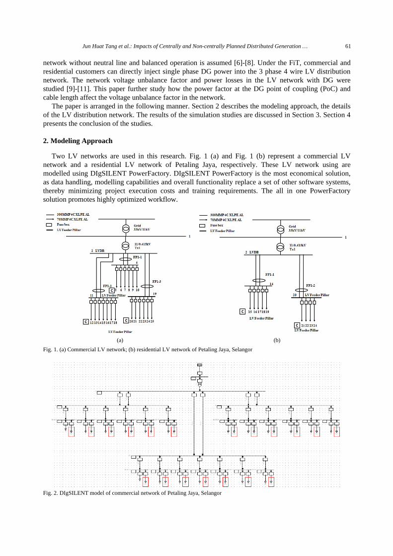
Fig. 2. DIgSILENT model of commercial network of Petaling Jaya, Selangor
62 International Journal of Smart Grid and Clean Energy, vol. 1, no. 1, September 2012
2.1. Commercial LV distribution network
DIgSILENT Power Factory is used to model the commercial distribution network. The network is integrated with DG connected to the grid with an increment of 1 KW per step up to 10 KW. The commercial network is radial in nature, and it is connected to a 1MVA, 11 KV/ 0.415KV 3 phases transformer equipped with off load tap changer at the high voltage side. With Delta-Grounded Wye connection, the transformer adeptly handles single phase load in any of the three phases. The earthing type used is T-T arrangement, where the potential earth of the customer is separated from the electricity supplier at the transformer side. Fig. 2 shows the DIgSILENT model of the commercial network. All customers are connected at the remote end of the feeder. This network consists of three double circuit feeders from the local substation transformer to distribution pillar using 300 sqmm 4C XLPE AL underground cable. Commercial customers’ service entrances are connected to the distribution pillar using 70 sqmm 4C XLPE AL underground cable. The parameters of underground cables and transformer rating are given in Table 1.
2.2. Residential LV distribution network
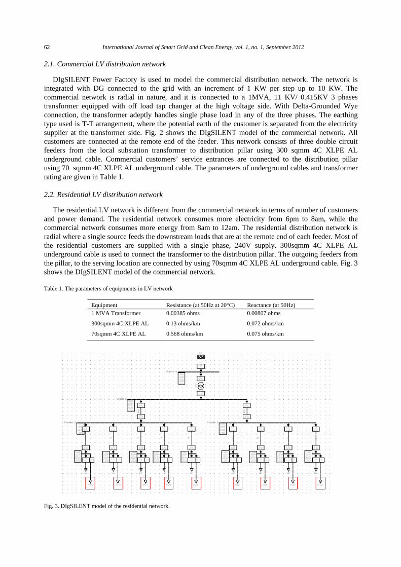
The residential LV network is different from the commercial network in terms of number of customers and power demand. The residential network consumes more electricity from 6pm to 8am, while the commercial network consumes more energy from 8am to 12am. The residential distribution network is radial where a single source feeds the downstream loads that are at the remote end of each feeder. Most of the residential customers are supplied with a single phase, 240V supply. 300sqmm 4C XLPE AL underground cable is used to connect the transformer to the distribution pillar. The outgoing feeders from the pillar, to the serving location are connected by using 70sqmm 4C XLPE AL underground cable. Fig. 3 shows the DIgSILENT model of the commercial network.
Table 1. The parameters of equipments in LV network
Equipment Resistance (at 50Hz at 20°C) Reactance (at 50Hz) 1 MVA Transformer 0.00385 ohms 0.00807 ohms
300sqmm 4C XLPE AL 0.13 ohms/km 0.072 ohms/km
70sqmm 4C XLPE AL 0.568 ohms/km 0.075 ohms/km
Fig. 3. DIgSILENT model of the residential network.
Jun Huat Tang et al.: Impacts of Centrally and Non-centrally Planned Distributed Generation … 63
2.3. Description of the methodology
The commercial and residential LV distribution networks are modeled with DIgSILENT PowerFactory to study the impacts of aggregated DG connected in the existing network. The simulation studies are to investigate the voltage unbalance factor and network losses in the LV distribution networks with two extreme scenarios:
1) Centrally planned DGs 2) Non-centrally planned DGs Centrally planned DGs maybe implement by the utility companies or government regulation body so
that DGs can be evenly distributed across the distribution network. The worst case scenario of non-centrally planned DGs is used in this simulation study where all DGs connected at the same phase. Besides that, the simulation work is extended to investigate the impacts of different feeder length and power factor at the point of coupling where DG is connected. Negative loads are used to represent the distributed generators that inject power into the LV distribution network.
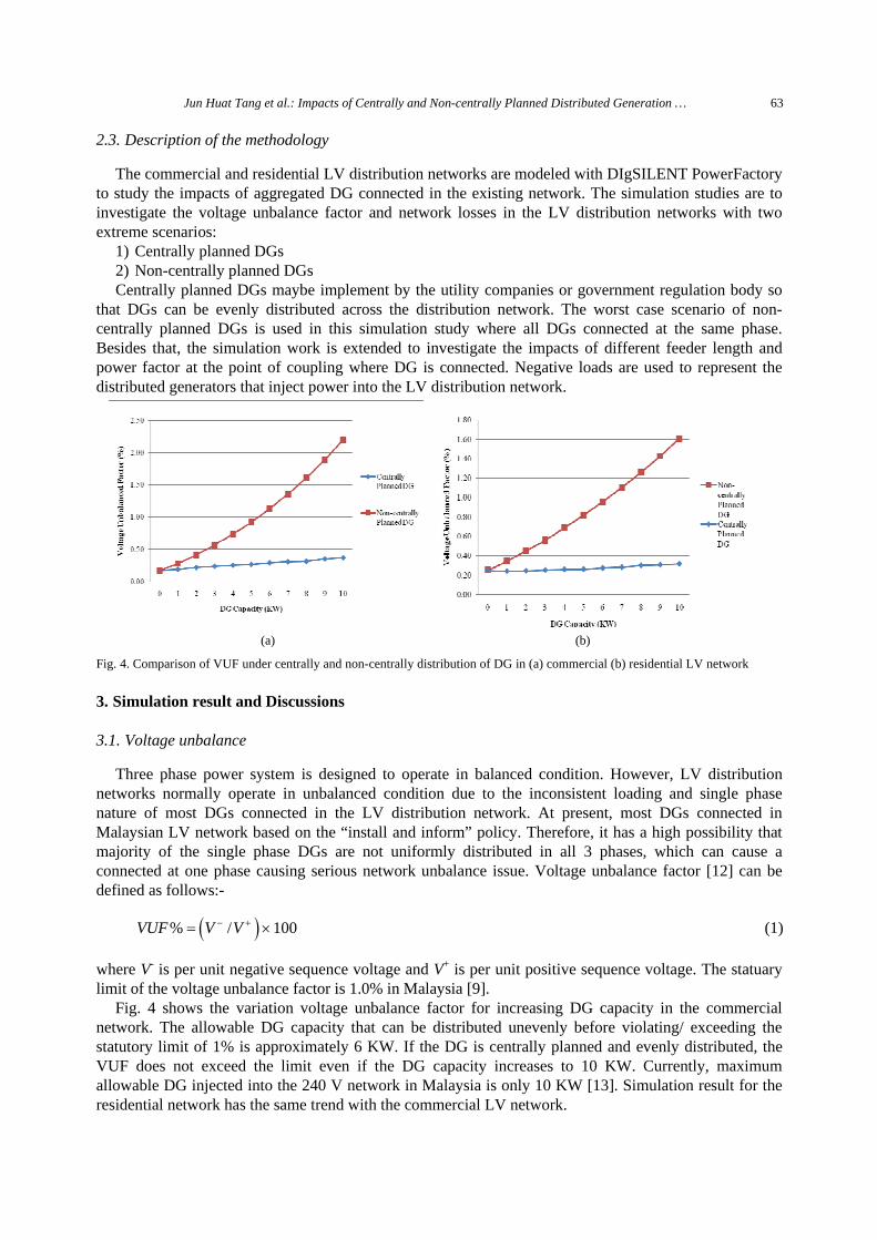
(a) (b)
Fig. 4. Comparison of VUF under centrally and non-centrally distribution of DG in (a) commercial (b) residential LV network
3. Simulation result and Discussions
3.1. Voltage unbalance
Three phase power system is designed to operate in balanced condition. However, LV distribution networks normally operate in unbalanced condition due to the inconsistent loading and single phase nature of most DGs connected in the LV distribution network. At present, most DGs connected in Malaysian LV network based on the “install and inform” policy. Therefore, it has a high possibility that majority of the single phase DGs are not uniformly distributed in all 3 phases, which can cause a connected at one phase causing serious network unbalance issue. Voltage unbalance factor [12] can be defined as follows:-
( )% / 100VUF V V− += × (1)
where V- is per unit negative sequence voltage and V+ is per unit positive sequence voltage. The statuary limit of the voltage unbalance factor is 1.0% in Malaysia [9].
Fig. 4 shows the variation voltage unbalance factor for increasing DG capacity in the commercial network. The allowable DG capacity that can be distributed unevenly before violating/ exceeding the statutory limit of 1% is approximately 6 KW. If the DG is centrally planned and evenly distributed, the VUF does not exceed the limit even if the DG capacity increases to 10 KW. Currently, maximum allowable DG injected into the 240 V network in Malaysia is only 10 KW [13]. Simulation result for the residential network has the same trend with the commercial LV network.
64 International Journal of Smart Grid and Clean Energy, vol. 1, no. 1, September 2012
3.2. Network power losses
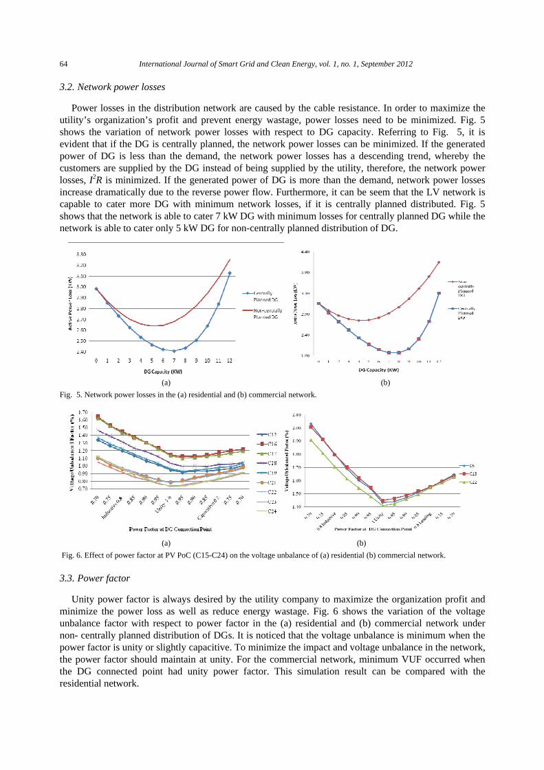
Power losses in the distribution network are caused by the cable resistance. In order to maximize the utility’s organization’s profit and prevent energy wastage, power losses need to be minimized. Fig. 5 shows the variation of network power losses with respect to DG capacity. Referring to Fig. 5, it is evident that if the DG is centrally planned, the network power losses can be minimized. If the generated power of DG is less than the demand, the network power losses has a descending trend, whereby the customers are supplied by the DG instead of being supplied by the utility, therefore, the network power losses, I2R is minimized. If the generated power of DG is more than the demand, network power losses increase dramatically due to the reverse power flow. Furthermore, it can be seem that the LV network is capable to cater more DG with minimum network losses, if it is centrally planned distributed. Fig. 5 shows that the network is able to cater 7 kW DG with minimum losses for centrally planned DG while the network is able to cater only 5 kW DG for non-centrally planned distribution of DG.
(a) (b)
Fig. 5. Network power losses in the (a) residential and (b) commercial network.
(a) (b)
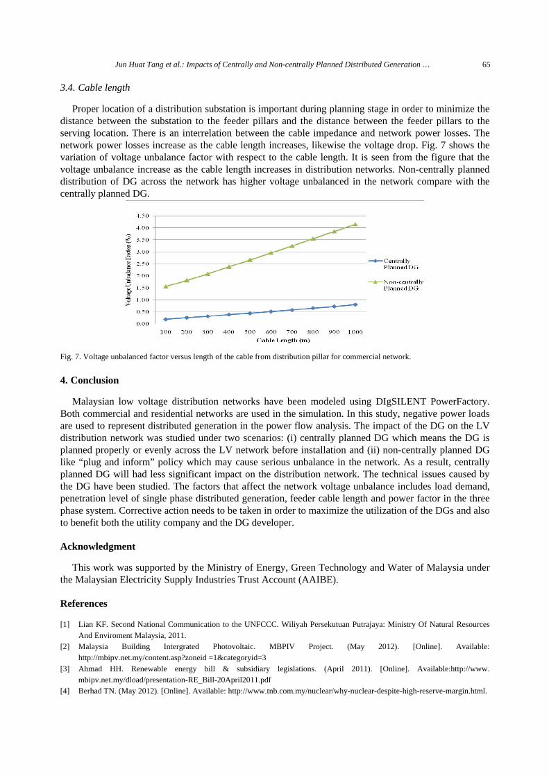
Fig. 6. Effect of power factor at PV PoC (C15-C24) on the voltage unbalance of (a) residential (b) commercial network.
3.3. Power factor
Unity power factor is always desired by the utility company to maximize the organization profit and minimize the power loss as well as reduce energy wastage. Fig. 6 shows the variation of the voltage unbalance factor with respect to power factor in the (a) residential and (b) commercial network under non- centrally planned distribution of DGs. It is noticed that the voltage unbalance is minimum when the power factor is unity or slightly capacitive. To minimize the impact and voltage unbalance in the network, the power factor should maintain at unity. For the commercial network, minimum VUF occurred when the DG connected point had unity power factor. This simulation result can be compared with the residential network.
Jun Huat Tang et al.: Impacts of Centrally and Non-centrally Planned Distributed Generation … 65
3.4. Cable length
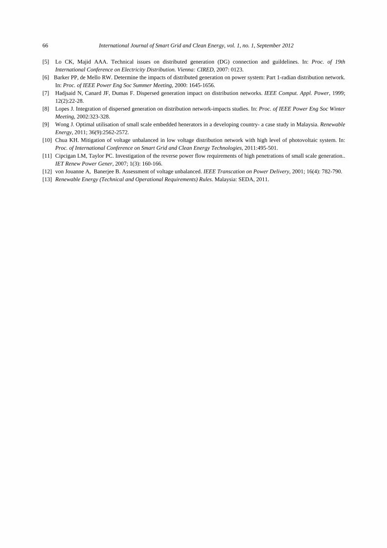
Proper location of a distribution substation is important during planning stage in order to minimize the distance between the substation to the feeder pillars and the distance between the feeder pillars to the serving location. There is an interrelation between the cable impedance and network power losses. The network power losses increase as the cable length increases, likewise the voltage drop. Fig. 7 shows the variation of voltage unbalance factor with respect to the cable length. It is seen from the figure that the voltage unbalance increase as the cable length increases in distribution networks. Non-centrally planned distribution of DG across the network has higher voltage unbalanced in the network compare with the centrally planned DG.
Fig. 7. Voltage unbalanced factor versus length of the cable from distribution pillar for commercial network.
4. Conclusion
Malaysian low voltage distribution networks have been modeled using DIgSILENT PowerFactory. Both commercial and residential networks are used in the simulation. In this study, negative power loads are used to represent distributed generation in the power flow analysis. The impact of the DG on the LV distribution network was studied under two scenarios: (i) centrally planned DG which means the DG is planned properly or evenly across the LV network before installation and (ii) non-centrally planned DG like “plug and inform” policy which may cause serious unbalance in the network. As a result, centrally planned DG will had less significant impact on the distribution network. The technical issues caused by the DG have been studied. The factors that affect the network voltage unbalance includes load demand, penetration level of single phase distributed generation, feeder cable length and power factor in the three phase system. Corrective action needs to be taken in order to maximize the utilization of the DGs and also to benefit both the utility company and the DG developer.
Acknowledgment
This work was supported by the Ministry of Energy, Green Technology and Water of Malaysia under the Malaysian Electricity Supply Industries Trust Account (AAIBE).
References
[1] Lian KF. Second National Communication to the UNFCCC. Wiliyah Persekutuan Putrajaya: Ministry Of Natural Resources And Enviroment Malaysia, 2011.
[2] Malaysia Building Intergrated Photovoltaic. MBPIV Project. (May 2012). [Online]. Available: http://mbipv.net.my/content.asp?zoneid =1&categoryid=3
[3] Ahmad HH. Renewable energy bill & subsidiary legislations. (April 2011). [Online]. Available:http://www. mbipv.net.my/dload/presentation-RE_Bill-20April2011.pdf
[4] Berhad TN. (May 2012). [Online]. Available: http://www.tnb.com.my/nuclear/why-nuclear-despite-high-reserve-margin.html.
66 International Journal of Smart Grid and Clean Energy, vol. 1, no. 1, September 2012
[5] Lo CK, Majid AAA. Technical issues on distributed generation (DG) connection and guildelines. In: Proc. of 19th International Conference on Electricity Distribution. Vienna: CIRED, 2007: 0123.
[6] Barker PP, de Mello RW. Determine the impacts of distributed generation on power system: Part 1-radian distribution network. In: Proc. of IEEE Power Eng Soc Summer Meeting, 2000: 1645-1656.
[7] Hadjsaid N, Canard JF, Dumas F. Dispersed generation impact on distribution networks. IEEE Comput. Appl. Power, 1999; 12(2):22-28.
[8] Lopes J. Integration of dispersed generation on distribution network-impacts studies. In: Proc. of IEEE Power Eng Soc Winter Meeting, 2002:323-328.
[9] Wong J. Optimal utilisation of small scale embedded henerators in a developing country- a case study in Malaysia. Renewable Energy, 2011; 36(9):2562-2572.
[10] Chua KH. Mitigation of voltage unbalanced in low voltage distribution network with high level of photovoltaic system. In: Proc. of International Conference on Smart Grid and Clean Energy Technologies, 2011:495-501.
[11] Cipcigan LM, Taylor PC. Investigation of the reverse power flow requirements of high penetrations of small scale generation.. IET Renew Power Gener, 2007; 1(3): 160-166.
[12] von Jouanne A, Banerjee B. Assessment of voltage unbalanced. IEEE Transcation on Power Delivery, 2001; 16(4): 782-790. [13] Renewable Energy (Technical and Operational Requirements) Rules. Malaysia: SEDA, 2011.