Impact of running gear design on train energy consumption · partner, is RUN2RAIL (Innovative...
94
0 Faculty of Civil and Industrial Engineering Master’s Degree in Transport Systems Engineering Mohamed Nabil Mohamed Mohamed Elsayed Eldigwi Matricola 1187465 Supervisor Co-Supervisor Prof.Gabriele Malavasi Prof. Riccardo Licciardello A.A. 2017-2018 Impact of running gear design on train energy consumption
Transcript of Impact of running gear design on train energy consumption · partner, is RUN2RAIL (Innovative...

0
Faculty of Civil and Industrial Engineering
Master’s Degree in Transport Systems Engineering
Mohamed Nabil Mohamed Mohamed Elsayed Eldigwi
Matricola 1187465
Supervisor Co-Supervisor
Prof.Gabriele Malavasi Prof. Riccardo Licciardello
A.A. 2017-2018
Impact of running gear design on train energy consumption

1
2
Impact of running gear design on train energy
consumption
Faculty of Civil and Industrial Engineering
Master’s Degree in Transport Systems Engineering
Mohamed Nabil Mohamed Mohamed Elsayed Eldigwi
Matricola 1187465
Supervisor Co-Supervisor
Prof. Gabriele Malavasi Prof. Riccardo Licciardello
A.A. 2017-2018

3
Acknowledgments
I would like to express my sincere gratitude to my supervisor Prof. Gabriele Malavasi,
Dr.Riccardo Licciardello, Marco Antongnoli and Massimiliano Bruner for the
continuous support of my master study and research, for the patience, motivation,
enthusiasm, and immense knowledge. Their guidance helped me in all the time during
my research and during writing my thesis.
I would like to thank every faculty member namely Professors Stefano Ricci, Guido
Gentile, Mattia Giovanni Crespi, Antonio Musso, Paola Di Mascio, Gaetano Fusco,
Massimo Guarascio and Liana Ricci, who have taught and guided me in all aspects.
I was one of the fortunate students who had the privilege of being taught by such
esteemed professors.
4
Index
INTRODUCTION ...................................................................................................................................... 1
STATE OF ART ...................................................................................................................................... 3
OBJECTIVES: ........................................................................................................................................ 5
1 THE ANATOMY OF RAILWAY RUNNING GEAR ..................................................................................... 6
1.1 MAIN FUNCTIONS OF THE RUNNING GEAR AND TERMINOLOGY ................................................ 6
1.2 BOGIE COMPONENTS .................................................................................................................... 7
A. WHEELSETS ................................................................................................................................. 7
B. AXLE BOXES ............................................................................................................................... 10
C. WHEELS ..................................................................................................................................... 13
D. SUSPENSION ............................................................................................................................. 14
E. BOGIE FRAME SHAPE ................................................................................................................ 32
F. BRAKING SYSTEM ...................................................................................................................... 37
G. CAR BODY CONNECTION .......................................................................................................... 40
2 IMPACTS OF INNOVATIVE RUNNING GEAR WITH COMPOSITE MATERIAL ....................................... 51
2.1 OVERVIEW OF A SINGLE AXEL RUNNING GEAR .......................................................................... 51
2.2 REFERENCE CASE: ROME–CIVITACASTELLANA–VITERBO RAILWAY ........................................... 57
2.4 MASS REDUCTION ....................................................................................................................... 60
2.5 WHEEL MAINTENANCE COSTS .................................................................................................... 62
2.6 Energy consumption ................................................................................................................... 65
CASE 1: ENERGY CONSUMPTION WITH VARYING SPEED ............................................................. 67
CASE 2: ENERGY CONSUMPTION WITH DISTANCE ....................................................................... 68
CASE 3: ENERGY CONSUMPTION WITH PASSENGER OCCUPANCY RATE ..................................... 70
CASE 4: ENERGY CONSUMPTION WITH AUXILIARY POWER ......................................................... 71
3 RELEVANT REGULATION AND STANDARDIZATION DOCUMENTS ...................................................... 72
3.1 IMPORTANCE OF REGULATION AND STANDARDIZATION DOCUMENTS .................................... 72
3.2 CONDITION MONITORING / HEALTH MONITORING ................................................................... 73
A. ISEE (1451) ................................................................................................................................ 73
B. OSA-CBM ................................................................................................................................... 74
3.3 Materials and manufacturing processes ..................................................................................... 77
4 MAIN CONCLUSIONS .......................................................................................................................... 80
REFERENCES ..................................................................................................................................... 83
ACRONYMS AND ABBREVIATIONS .................................................................................................... 85
5
List of figures Fig.I.1: SF300 Running gear Siemens Transportation Systems................................................. 2
Fig.I.2: conventional running gear vehicle.................................................................................3
Fig.I.3: Single axle running gear vehicle.....................................................................................3
Fig.I.4: Copenhagen S train........................................................................................................4
Fig.I.5: High-speed train with bogie type locomotives and single-axle coaches.......................4
Fig.1.1: Wheelset typology........................................................................................................9
Fig.1.2: The rolling surface of wheels........................................................................................9
Fig.1.3: Axle boxes....................................................................................................................12
Fig.1.4: Axle boxes for high speed train....................................................................................13
Fig.1.5: type of wheels..............................................................................................................14
Fig.1.6: suspension classification..............................................................................................15
Fig.1.7: Airspring.......................................................................................................................16
Fig.1.8: Helical springs...............................................................................................................17
Fig.1.9: Flexi-coil........................................................................................................................18
Fig.1.10: Rubber for primary and secondary suspension..........................................................19
Fig.1.11: Hourglass shape for secondary suspension................................................................20
Fig.1.12: Classification of suspensions systems according to the geometry.............................21
Fig.1.13: Cylindrical guides inside the spring............................................................................22
Fig.1.14: DT200 suspension......................................................................................................23
Fig.1.15: Cylindrical laminated rubber......................................................................................24
Fig.1.16: Swing arm...................................................................................................................25
Fig.1.17: Swing arm on CRH-1A train........................................................................................25
Fig.1.18: Horizontal leaf springs................................................................................................26
Fig.1.19: MD-522 Bogies by Bombardier...................................................................................26
Fig.1.20: Two diagonal link arms...............................................................................................27
Fig.1.21: CL 624 Bogies by Alstom.............................................................................................28
Fig.1.22: Horn liner guides........................................................................................................29
Fig.1.23: Cylindrical stubs.........................................................................................................30
Fig.1.24: Friction dampers........................................................................................................31
Fig.1.25: Hydraulic dampers.....................................................................................................32

6
Fig.1.26: Designs of bogie frame............................................................................................33
Fig.1.27: Open H-frame..........................................................................................................33
Fig.1.28: External & Internal Open H-frame..........................................................................34
Fig.1.29: Open H-frame.........................................................................................................35
Fig.1.30: Three-piece frame..................................................................................................36
Fig.1.31: Classification of braking system.............................................................................37
Fig.1.32: Disc brake...............................................................................................................38
Fig.1.33: Wheel-mounted brake discs...................................................................................38
Fig.1.34: Classification of braking system..............................................................................39
Fig.1.35: Magnetic track brakes............................................................................................40
Fig.1.36: Classification of carbody connection......................................................................40
Fig.1.37: High location of the pivot point..............................................................................41
Fig.1.38: Low location of the pivot point...............................................................................41
Fig.1.39: Flat center plate......................................................................................................43
Fig.1.40: Watts linkage..........................................................................................................43
Fig.1.41: Watts linkage configuration....................................................................................44
Fig.1.42: Watts linkage..........................................................................................................45
Fig.1.43: Classification of tilting.............................................................................................46
Fig.1.44: Steering...................................................................................................................47
Fig.1.45: Classification of axel guidance.................................................................................48
Fig.1.46: Steering linkages & Actuator....................................................................................49
Fig.1.47: different systems of an axle.....................................................................................50
Fig.1.47: Running gear – case study........................................................................................51
Fig.2.1: DLR Next Generation Train (NGT) (design study by ids, Hamburg)............................53
Fig. 2.2: streeing principles for independently rotating wheels..............................................54
Fig.2.3: control for mechatronic guidance..............................................................................56
Fig.2.4: single axe running gear & Wheel module...................................................................57
Fig.2.5: Map of the line............................................................................................................58
Fig.2.6: Elettromotrice 310, terza generazione........................................................................59
Fig.2.7: configuration of the train............................................................................................60

7
List of graphs
Graph 1: time speed for 1 stop.............................................................................................66
Graph 2: Speed versus energy for 1 stop……………………………………………………………………….…67
Graph 3: Speed versus energy for 7 stops………………………………………………………………………..68
Graph 4: Energy versus distance for 1 stop………………………………………………………………....….68
Graph 5: Energy versus distance for 7 stops…………………………………………………………………….69
Graph 6: Energy consumption reduction with passenger…………………………………….………....70
Graph 7: Auxiliary power vs energy consumption for 1 stop…………………………………………...71
Graph 8: Auxiliary power vs energy consumption for 1 stop…………………………………………...71
1
INTRODUCTION
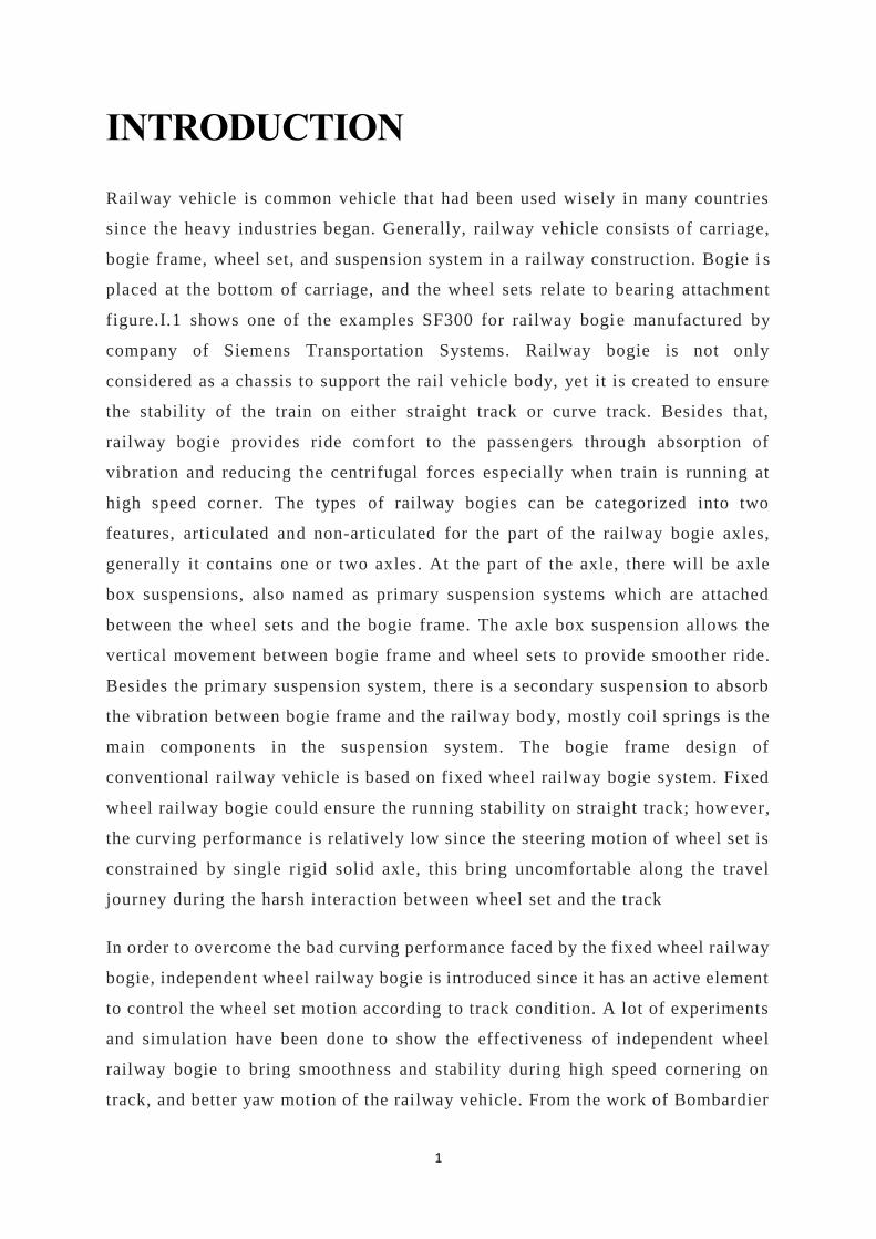
Railway vehicle is common vehicle that had been used wisely in many countries
since the heavy industries began. Generally, railway vehicle consists of carriage,
bogie frame, wheel set, and suspension system in a railway construction. Bogie i s
placed at the bottom of carriage, and the wheel sets relate to bearing attachment
figure.I.1 shows one of the examples SF300 for railway bogie manufactured by
company of Siemens Transportation Systems. Railway bogie is not only
considered as a chassis to support the rail vehicle body, yet it is created to ensure
the stability of the train on either straight track or curve track. Besides that,
railway bogie provides ride comfort to the passengers through absorption of
vibration and reducing the centrifugal forces especially when train is running at
high speed corner. The types of railway bogies can be categorized into two
features, articulated and non-articulated for the part of the railway bogie axles,
generally it contains one or two axles . At the part of the axle, there will be axle
box suspensions, also named as primary suspension systems which are attached
between the wheel sets and the bogie frame. The axle box suspension allows the
vertical movement between bogie frame and wheel sets to provide smooth er ride.
Besides the primary suspension system, there is a secondary suspension to absorb
the vibration between bogie frame and the railway body, mostly coil springs is the
main components in the suspension system. The bogie frame design of
conventional railway vehicle is based on fixed wheel railway bogie system. Fixed
wheel railway bogie could ensure the running stability on straight track; how ever,
the curving performance is relatively low since the steering motion of wheel set is
constrained by single rigid solid axle, this bring uncomfortable along the travel
journey during the harsh interaction between wheel set and the track
In order to overcome the bad curving performance faced by the fixed wheel railway
bogie, independent wheel railway bogie is introduced since it has an active element
to control the wheel set motion according to track condition. A lot of experiments
and simulation have been done to show the effectiveness of independent wheel
railway bogie to bring smoothness and stability during high speed cornering on
track, and better yaw motion of the railway vehicle. From the work of Bombardier

2
transportation, it stated that the independent wheel set can run steadily even in
high speed and smooth track cornering. With the invention of this bogie system,
curving performance is considered upgraded without sacrificed the running
stability of railway vehicle, the vibration of wheels and rail is also reduced to
ensure the driving comfort. The independent wheel railway bogie has a simple
linkage between wheel set and the bogie, by applying forces to the leverage to
actuate the link for desired movement of wheel set. The independ ent wheel railway
bogie includes wheel sets which are mounted separately near the end of side frame
by connecting with a connector. Besides that, there are four solid bars joined with
the bottom middle bar, this is a main bar to ensure the movement of whee l sets.
Fig.I.1: SF300 Running gear Siemens Transportation Systems

3
STATE OF ART
The use of new material for running gear such as composit material and single
axle configurations (figure.I.2) in stand of conventional one (figure.I.3) is
increasing for the new generation of rail vehicles in these days. In Europe there
are many commercial uses of the single axle configurations for LRT, commuter
trains and high-speed applications
Fig.I.2: conventional running gear vehicle
Fig.I.3: Single axle running gear vehicle
The simple structure leads to the expectation of low initial and running cost of
vehicles. For LRT the relative ease with which low floor arrangements is very
attractive for the accessibility of passengers. With this configuration the length of
the car body should be shortened to keep the wheel load within the limits required
by for track capacity. The short body enables a wider body because the amount
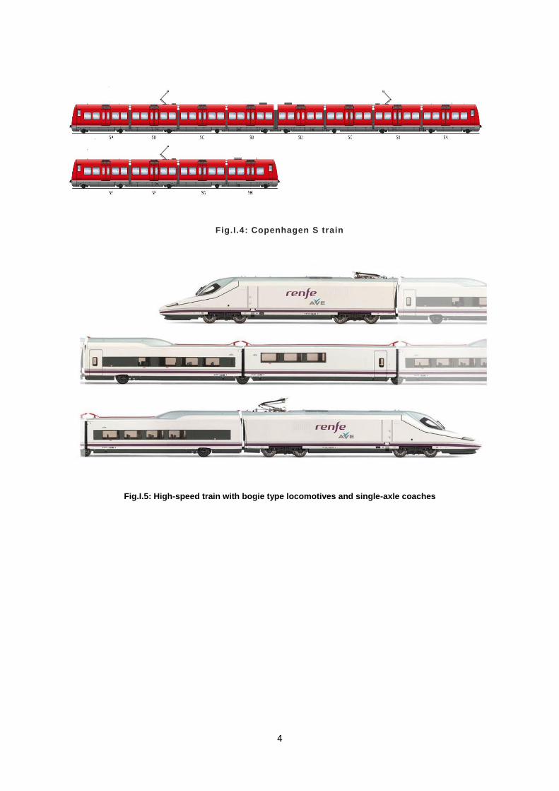
(Figure.I.4) – (Figure.I.5) of over-hang [1]. Therefore, it contributes to higher
capacity of the trains. Since bogies take a substantial share of overall train mass,
single-axle bogies make an appreciable contribution to mass reduction. Single-axle
bogies also have potential in freight services.
4
Fig.I.4: Copenhagen S train
Fig.I.5: High-speed train with bogie type locomotives and single-axle coaches
5
OBJECTIVES:
this thesis examines a case study with:
a single-axle vehicle with compiste material “light weight material” and
considering the possibilities of benefiting
In practical terms, as a case study, single-axle train-set is hypothesized for
operation on metro. The aim of this thesis is to understand the potential of reducing
wheel-set maintenance costs and energy consumption and in particular:
1. to quantify, through assumptions, the mass reductions of running gear
possible;
2. to quantify the corresponding energy consumption reduction on a
hypothetical line;
3. to quantify, through assumptions, the effect on wheel -set maintenance costs of
mass reduction and use of actively-steered wheels with the CAF series 8400.
The current solutions analyzed for reducing the mass is using composite materials
such as kevler Fibre composite whose costs are high but the density of the material
is less compared with steel’s. This light -weight material can be helpful in reducing
pollution (environmental aspect) and can be supportive in reducing costs
(economical aspect).
Being a new bogie concept produced in small numbers and tailored to specific
vehicles, costs are still relatively high but are expected to drop as soon as bigger
production number are achieved. Energy efficiency effects are especially high in
local and regional transport.
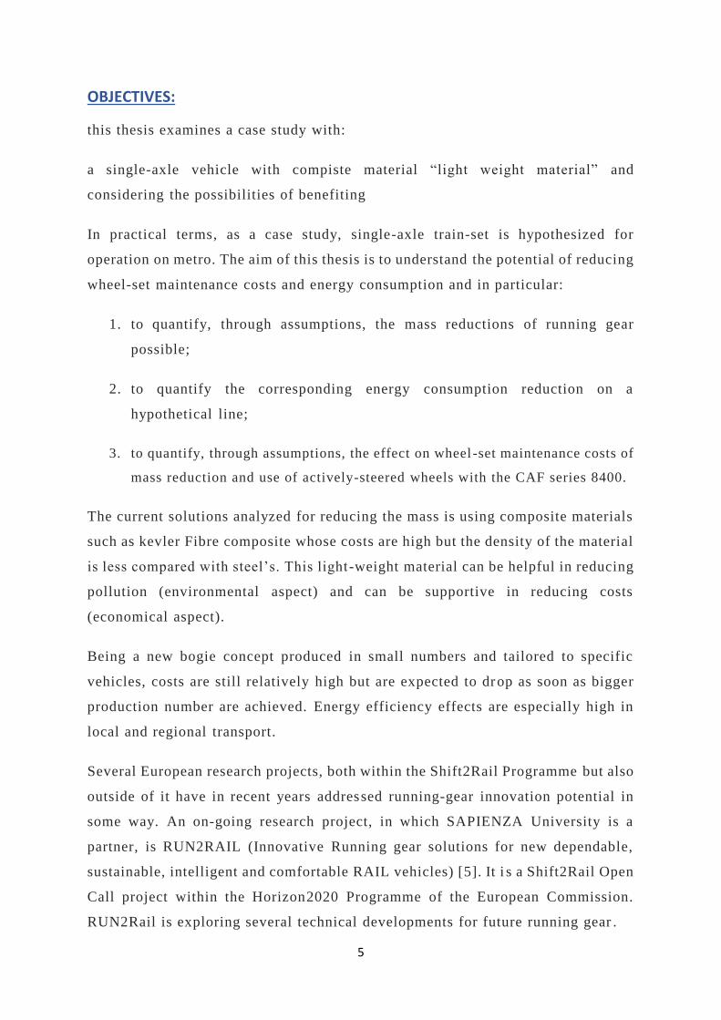
Several European research projects, both within the Shift2Rail Programme but also
outside of it have in recent years addressed running-gear innovation potential in
some way. An on-going research project, in which SAPIENZA University is a
partner, is RUN2RAIL (Innovative Running gear solutions for new dependable,
sustainable, intelligent and comfortable RAIL vehicles) [5]. It i s a Shift2Rail Open
Call project within the Horizon2020 Programme of the European Commission.
RUN2Rail is exploring several technical developments for future running gear .
6
1 THE ANATOMY OF RAILWAY
RUNNING GEAR
1.1 MAIN FUNCTIONS OF THE RUNNING GEAR AND TERMINOLOGY
The principal difference between a railway vehicle and other types of wheeled
transport is the guidance provided by the track. The surface of the rails not only
supports the wheels, but also guides them in a lateral direction. The rails and the
switches change the rolling direction of wheels and thus determine the travelling
direction of the railway vehicle. The running gear is the system that provides safe
motion of the vehicle along railway track. The running gear includes such
components as wheelsets with axle boxes, the elastic suspension, the brakes, the
traction drive, and the device to transmit traction and braking forces to the car
body [2].
Its main functions are:
• Transmission and equalization of the vertical load from the wheels of the
vehicle to the rails;
• Guidance of vehicle along the track;
• Control of the dynamic forces due to motion over track irregularities, in
curves, switches and after impacts between the cars;
• Efficient damping of excited oscillations ;
• Application of traction and braking forces;
Depending on the running gear, the vehicles may be described as bogied or bogie -
less. In vehicles without bogies the suspension, brakes, and traction equipment are
mounted on the car body frame. The traction and braking forces are transmitte d
through traction rods or axle box guides (sometimes known as “horn guides”).
Conventional two-axle vehicles will generate larger forces in tight curves than the
equivalent bogie vehicle; therefore, their length is limited. Running gear mounted

7
on a separate frame that can turn relative to the vehicle body is known as a bogie
(or truck). The number of wheelsets that they unite classifies the bogies. The most
common type is the two-axle bogie, but three- and four-axle bogies are also
encountered, often on locomotives.
Previously, the bogies simply allowed the running gear to turn in a horizontal
plane relative to the car body thus making it possible for the wheelsets to have
smaller angles of attack in curves. In modern bogies, the bogie frame transmits all
the longitudinal, lateral, and vertical forces between the car body and the
wheelsets. The frame also carries braking equipment, traction drive, suspension,
and dampers. It may also house tilting devices, lubrication devices for wheel -rail
contact and mechanisms to provide radial positioning of wheelsets in curves.
Bogie vehicles are normally heavier than two-axle vehicles. However, the design
of railway vehicles with bogies is often simpler than for two-axle vehicles and this
may provide reliability and maintenance benefits.
1.2 BOGIE COMPONENTS
A. WHEELSETS
A wheelset comprises two wheels rigidly connected by a common axle. The
wheelset is supported on bearings mounted on the axle journals.
The wheelset provides [2]:
• The necessary distance between the vehicle and the track
• The guidance that determines the motion within the rail gauge, including at
curves and switches
• The means of transmitting traction and braking forces to the rails to
accelerate and decelerate the vehicle
The design of the wheelset depends on:
• The type of the vehicle (traction or trailing)
• The type of braking system used (shoe brake, brake disc on the axle, or
brake disc on the wheel)
8
• The construction of the wheel center and the position of bearings on the
axle (inside or outside)
• The desire to limit higher frequency forces by using resilient elements
between the wheel center and the tyre
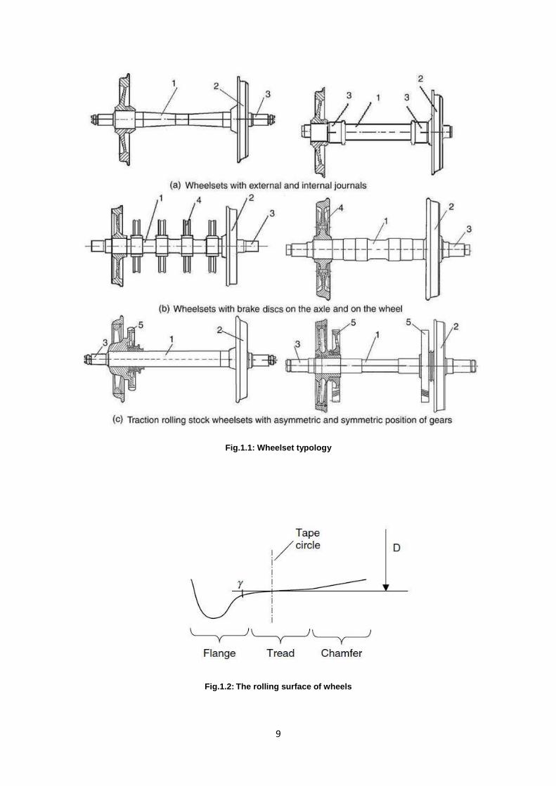
The main types of wheelset design are shown in FIGURE.1.1. Despite the variety
of designs, all these wheelsets have two common features: the rigid connect ion
between the wheels through the axle and the cross-sectional profile of the wheel
rolling surface, named wheel profile.
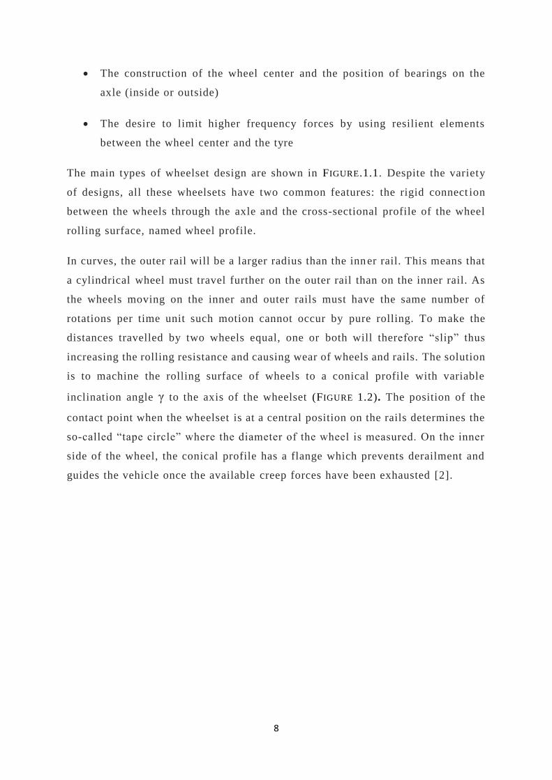
In curves, the outer rail will be a larger radius than the inner rail. This means that
a cylindrical wheel must travel further on the outer rail than on the inner rail. As
the wheels moving on the inner and outer rails must have the same number of
rotations per time unit such motion cannot occur by pure rolling. To make the
distances travelled by two wheels equal, one or both will therefore “slip” thus
increasing the rolling resistance and causing wear of wheels and rails. The solution
is to machine the rolling surface of wheels to a conical profile with variable
inclination angle γ to the axis of the wheelset (FIGURE 1.2). The position of the
contact point when the wheelset is at a central position on the rails determines the
so-called “tape circle” where the diameter of the wheel is measured. On the inner
side of the wheel, the conical profile has a flange which prevents derailment and
guides the vehicle once the available creep forces have been exhausted [2].
9
Fig.1.1: Wheelset typology
Fig.1.2: The rolling surface of wheels

10
B. AXLE BOXES
The axle box is the device that allows the wheelset to rotate by providing the
bearing housing and the mountings for the primary suspension to attach the
wheelset to the bogie or vehicle frame [2].
The axle box transmits longitudinal, lateral, and vertical forces from the wheelset
on to the other bogie elements. Axle boxes are classified according to:
• Their position on the axle depending on whether the journals are outside or
inside.
• The bearing type used, either roller or plain bearings .
• The external shape of the axle box is determined by the method of
connection between the axle box and the bogie frame and aims to achieve
uniform distribution of forces on the bearing.
Internal construction of the axle box is determined by the bearing and its sealing
method. Axle boxes with plain bearing consist of the housing , the bearing itself
which is usually made of alloy with low friction coefficient (e.g., bronze or white
metal), the bearing shell which transmits the forces from the axle box housing to
the bearing, a lubrication device which lubricates the axle journal. Front and rear
seals prevent dirt and foreign bodies entering the axle box, while the front seal
can be removed to monitor the condition of the bearing and add lubricant. Vertical
and longitudinal forces are transmitted through the internal surface of the bearing
and lateral forces by its faces.
Plain bearing axle boxes are now largely obsolete as they have several serious
disadvantages:
• High friction coefficient when starting from rest
• Poor reliability
• Labour-intensive maintenance
• Environmental pollution

11
However, from a vehicle dynamic behavior point of view, axle boxes with plain
bearings had certain positive features. In recent years, plain bearing axle boxes
that do not require lubrication have been reintroduced on certain types of rolling
stock though their use is still rare.
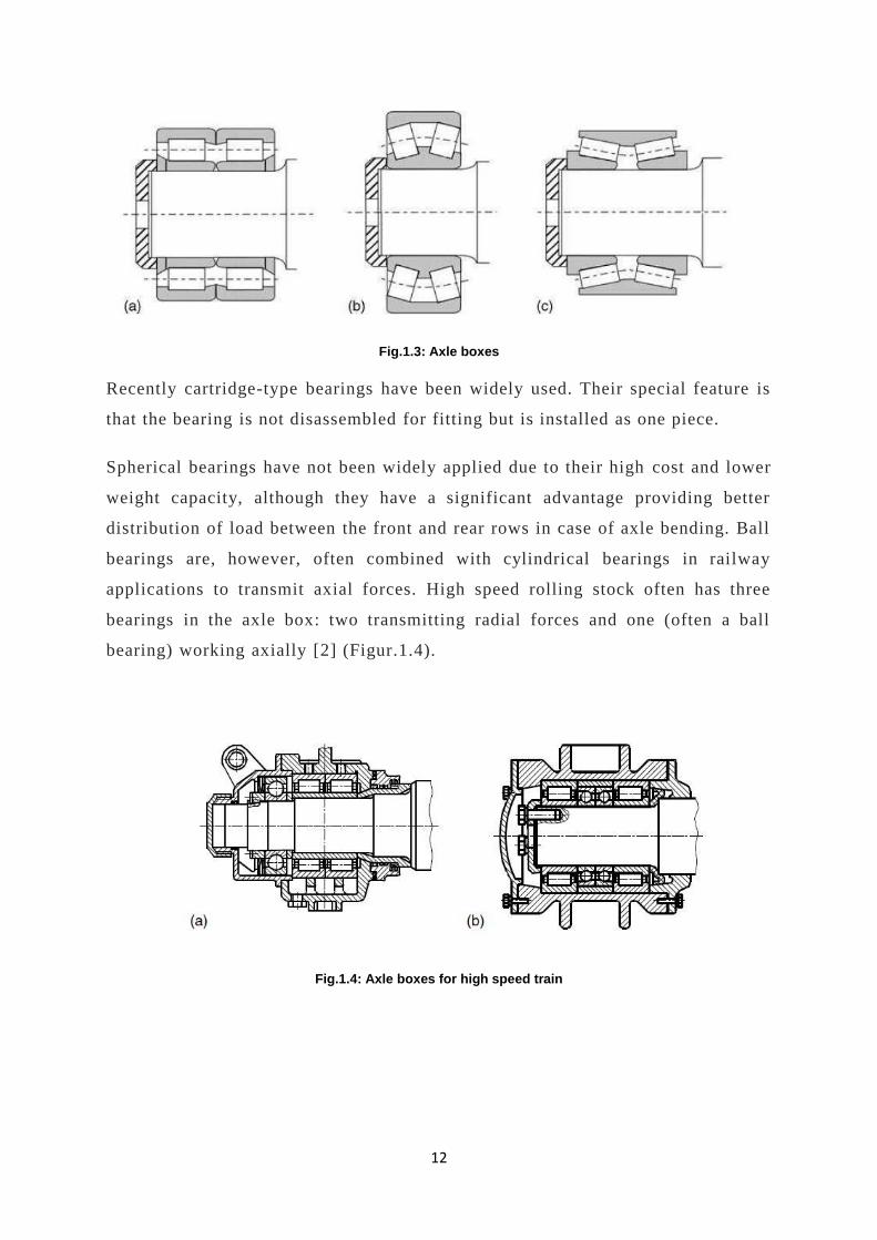
Axle boxes with roller type bearings (Figure.1.3) are classified according to:
• The bearing type (cylindrical, conical, spherical)
• The fitting method (press-fit, shrink-fit, bushing-fit)
The main factor that determines the construction of the axle box is the way it
experiences the axial forces and distributes the load between the rollers.
Cylindrical roller bearings have high dynamic capacity in the radial direction, but
do not transmit axial forces (Figure.1.3a). Experience in operation of railway
rolling stock showed that the faces of rollers can resist lateral forces. However, to
do this successfully it is necessary to regulate not only the diameter, but also the
length of rollers, and the radial, and axial clearances.
Conical bearings (Figure.1.3b and c) transmit axial forces through the cylindrical
surface due to its inclination to the rotation axis. This makes it necessary to keep
the tolerances on roller diameters and clearances almost an order of magnitude
tighter than for cylindrical bearings. In addition, conical bearings have higher
friction coefficients compared to the radial roller bearings and therefore generate
more heat. This not only increases traction consumption, but also creates
difficulties for diagnostics of axle box units during motion.
12
Fig.1.3: Axle boxes
Recently cartridge-type bearings have been widely used. Their special feature is
that the bearing is not disassembled for fitting but is installed as one piece.
Spherical bearings have not been widely applied due to their high cost and lower
weight capacity, although they have a significant advantage providing better
distribution of load between the front and rear rows in case of axle bending. Ball
bearings are, however, often combined with cylindrical bearings in railway
applications to transmit axial forces. High speed rolling stock often has three
bearings in the axle box: two transmitting radial forces and one (often a ball
bearing) working axially [2] (Figur.1.4).
Fig.1.4: Axle boxes for high speed train

13
C. WHEELS
Wheels and axles are the most critical parts of the railway rolling stock.
Mechanical failure or exceedance of design dimensions can cause derailment.
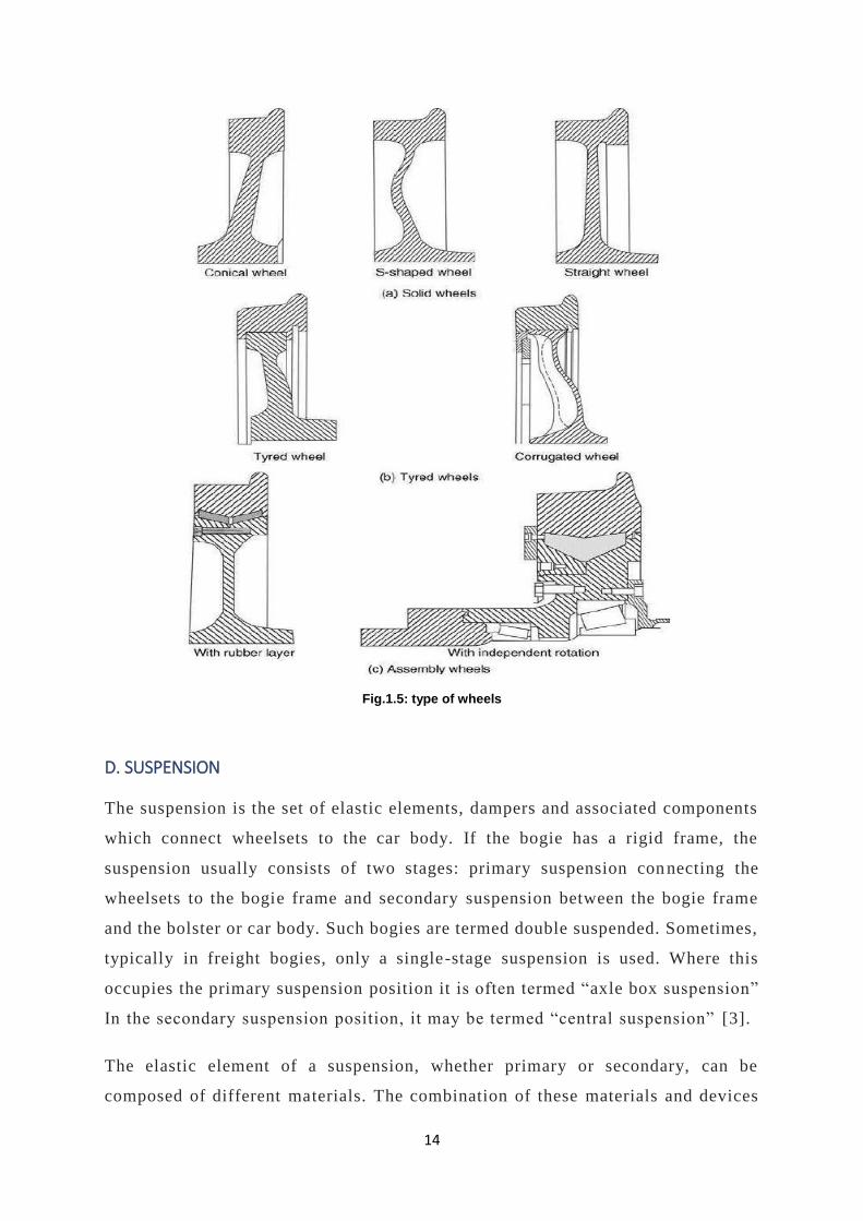
Wheels are classified into solid, tyre, and assembly types as shown in Figure.1.5.
Solid wheels [2] (Figure 1.5a) have three major elements: the tyre, the disc, and
the hub, and mainly differ in the shape of the disc.
Tyred wheels (Figure 1.5b) have a tyre fitted to the wheel disc that can be removed
and replaced when it reaches its maximum turning limit.
Wheels may have straight, conical, S-shaped, spoked, or corrugated type discs
when viewed in cross-section. A straight disc reduces the weight of the
construction and can be shaped such that the metal thickness corresponds to the
level of local stress. The conical and S-shape discs serve to increase the flexibility
of the wheel, therefore reducing the interaction forces between the wheels and the
rails. Corrugated discs have better resistance to lateral bending. The desire of
reducing wheel-rail interaction forces by reducing the unspring mass has led to
development of resilient wheels (Figure 1.5c) that incorporate a layer of material
with low elasticity modulus (rubber, polyurethane). These help to attenuate the
higher frequency forces acting at the wheel-rail interface.
14
Fig.1.5: type of wheels
D. SUSPENSION
The suspension is the set of elastic elements, dampers and associated components
which connect wheelsets to the car body. If the bogie has a rigid frame, the
suspension usually consists of two stages: primary suspension con necting the
wheelsets to the bogie frame and secondary suspension between the bogie frame
and the bolster or car body. Such bogies are termed double suspended. Sometimes,
typically in freight bogies, only a single-stage suspension is used. Where this
occupies the primary suspension position it is often termed “axle box suspension”
In the secondary suspension position, it may be termed “central suspension” [3].
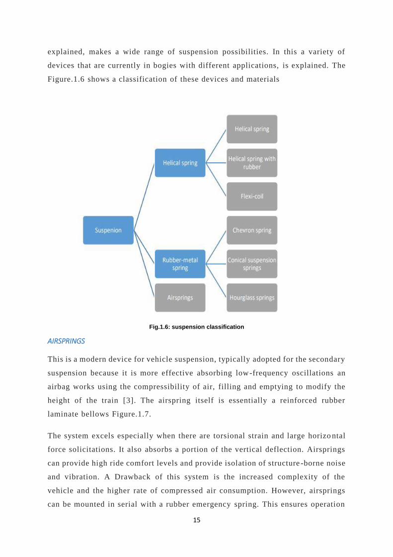
The elastic element of a suspension, whether primary or secondary, can be
composed of different materials. The combination of these materials and devices
15
explained, makes a wide range of suspension possibilities. In this a variety of
devices that are currently in bogies with different applications, is explained. The
Figure.1.6 shows a classification of these devices and materials
Fig.1.6: suspension classification
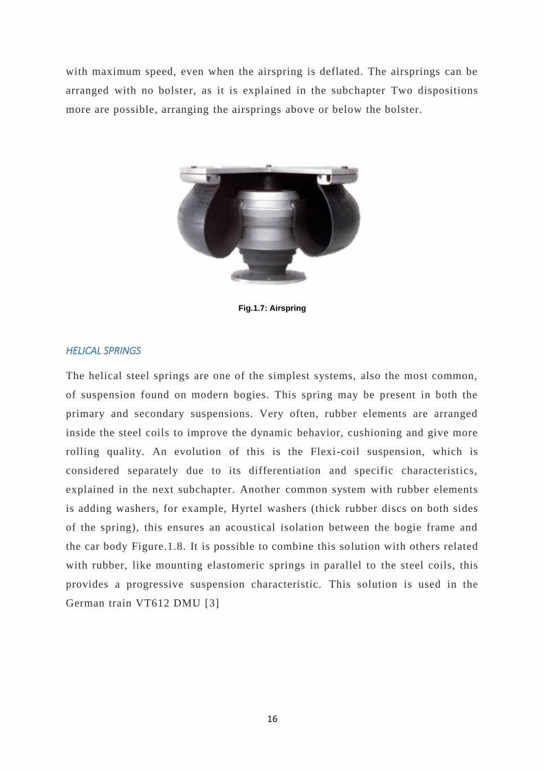
AIRSPRINGS
This is a modern device for vehicle suspension, typically adopted for the secondary
suspension because it is more effective absorbing low-frequency oscillations an
airbag works using the compressibility of air, filling and emptying to modify the
height of the train [3]. The airspring itself is essentially a reinforced rubber
laminate bellows Figure.1.7.
The system excels especially when there are torsional strain and large horizo ntal
force solicitations. It also absorbs a portion of the vertical deflection. Airsprings
can provide high ride comfort levels and provide isolation of structure -borne noise
and vibration. A Drawback of this system is the increased complexity of the
vehicle and the higher rate of compressed air consumption. However, airsprings
can be mounted in serial with a rubber emergency spring. This ensures operation
16
with maximum speed, even when the airspring is deflated. The airsprings can be
arranged with no bolster, as it is explained in the subchapter Two dispositions
more are possible, arranging the airsprings above or below the bolster.
Fig.1.7: Airspring
HELICAL SPRINGS
The helical steel springs are one of the simplest systems, also the most common,
of suspension found on modern bogies. This spring may be present in both the
primary and secondary suspensions. Very often, rubber elements are arranged
inside the steel coils to improve the dynamic behavior, cushioning and give more
rolling quality. An evolution of this is the Flexi-coil suspension, which is
considered separately due to its differentiation and specific characteristics,
explained in the next subchapter. Another common system with rubber elements
is adding washers, for example, Hyrtel washers (thick rubber discs on both sides
of the spring), this ensures an acoustical isolation between the bogie frame and
the car body Figure.1.8. It is possible to combine this solution with others related
with rubber, like mounting elastomeric springs in parallel to the steel coils, this
provides a progressive suspension characteristic. This solution is used in the
German train VT612 DMU [3]
17
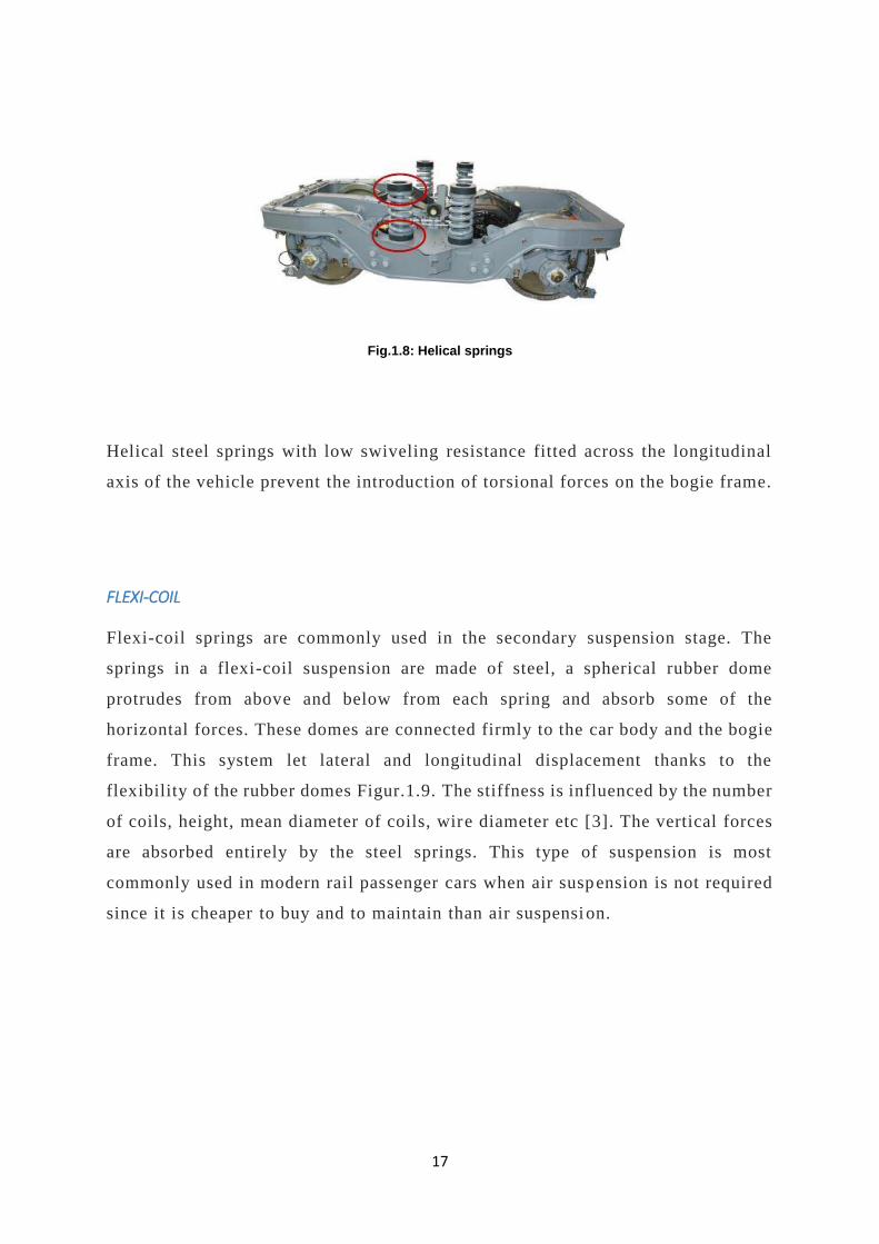
Fig.1.8: Helical springs
Helical steel springs with low swiveling resistance fitted across the longitudinal
axis of the vehicle prevent the introduction of torsional forces on the bogie frame.
FLEXI-COIL
Flexi-coil springs are commonly used in the secondary suspension stage. The
springs in a flexi-coil suspension are made of steel, a spherical rubber dome
protrudes from above and below from each spring and absorb some of the
horizontal forces. These domes are connected firmly to the car body and the bogie
frame. This system let lateral and longitudinal displacement thanks to the
flexibility of the rubber domes Figur.1.9. The stiffness is influenced by the number
of coils, height, mean diameter of coils, wire diameter etc [3]. The vertical forces
are absorbed entirely by the steel springs. This type of suspension is most
commonly used in modern rail passenger cars when air suspension is not required
since it is cheaper to buy and to maintain than air suspension.

18
Fig.1.9: Flexi-coil
An analysis from the University of Pardubice (Czech Republic) summarized in the
article “The effect of spring pads in the secondary suspension of railway vehicles
on bogie yaw resistance” concluded:
“At a slow run in a curve, the bogie yaw resistance is low. However, the resistance
is also low at the run of the vehicle in a straight track which can lead to worse
riding stability characterized by a lower critical speed of the vehicle. In the case
of a run in a curve at a high value of the cant deficiency, in which the need of a
minimized bogie yaw resistance is the most important, the reduction of the bogie
yaw resistance is not so significant, on the contrary.” [3]
RUBBER AND RUBBER-METAL SPRINGS
The elastomeric springs are suspensions made of rubber or composite materials
that have an important natural hysteresis and are optimal to avoid high -frequency
vibrations. The behavior of these materials varies according to their composition
and its shape, presenting values of resilience, in general, higher than steel.
Conical rubber-metal springs provide an optimal filtration of vibrations in the axle
box, avoids fatigue problems by transmission of vibrations to the axle. Conical
rubber-metal springs also provide three linear modes of flexibility, lateral,
longitudinal and vertical. Modifying the geometry, different properties are
reached. Therefore, this suspension is used to provide a bogie with the axle
guidance capability.
19
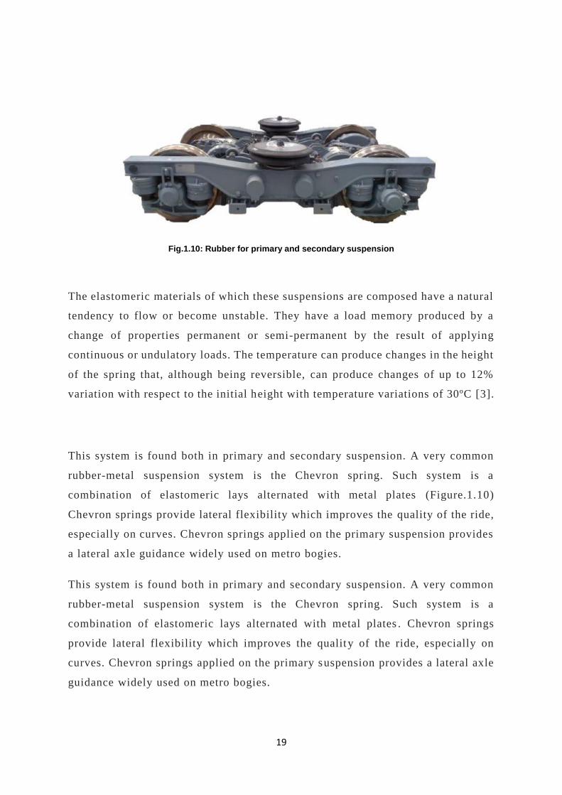
Fig.1.10: Rubber for primary and secondary suspension
The elastomeric materials of which these suspensions are composed have a natural
tendency to flow or become unstable. They have a load memory produced by a
change of properties permanent or semi-permanent by the result of applying
continuous or undulatory loads. The temperature can produce changes in the height
of the spring that, although being reversible, can produce changes of up to 12%
variation with respect to the initial height with temperature variations of 30ºC [3].
This system is found both in primary and secondary suspension. A very common
rubber-metal suspension system is the Chevron spring. Such system is a
combination of elastomeric lays alternated with metal plates (Figure.1.10)
Chevron springs provide lateral flexibility which improves the quality of the ride,
especially on curves. Chevron springs applied on the primary suspension provides
a lateral axle guidance widely used on metro bogies.
This system is found both in primary and secondary suspension. A very common
rubber-metal suspension system is the Chevron spring. Such system is a
combination of elastomeric lays alternated with metal plates . Chevron springs
provide lateral flexibility which improves the quality of the ride, especially on
curves. Chevron springs applied on the primary suspension provides a lateral axle
guidance widely used on metro bogies.

20
Fig.1.11: Hourglass shape for secondary suspension
Lastly, there are elastomeric springs applied to the secondary suspension with an
hourglass shape (Figure1.11). These springs allow lateral and longitudinal
displacement. In addition, rubber provides advantages such as their simplicity of
manufacturing, low maintenance cost, less weight than steel and a lo ng service
life. This type of suspension offers a high load capacit y and can store more elastic
energy per unit volume than metals [3].
CLASSIFICATION OF SUSPENSIONS SYSTEMS ACCORDING TO THE GEOMETRY
The primary suspension should connect the axlebox to the bogie frame. This
should be an elastic connection due to the ax lebox must have a stroke. The
different systems that allow this movement are classified (figure.1.12)

21
Fig.1.12: Classification of suspensions systems according to the geometry
CYLINDRICAL GUIDES INSIDE THE SPRING
This consists of a barrel inside the helical spring attached to the axlebox and a
guide that slides inside of it attached to the bogie frame (Figure .1.13). The barrels
are attached to the axlebox with rubber coaxial bushings, t herefore, provides some
flexibility between the wheelset and the bogie frame in the longitudinal and
vertical directions. Due to the axial symmetry of the rubber bushes, the stiffness
in longitudinal and vertical directions in the same [3].

22
Fig.1.13: Cylindrical guides inside the spring
Another system of guides are the ones with cylindrical laminated rubber achieved
concentrically inside the helical spring (Figure .1.14). This arrangement allows
lateral and longitudinal movement of the axlebox due to the flexibility of the
rubber. This system is more compact than the system with the cylindrical rubber
guides outside the spring (explained below). Due to the rubber guide s hould be
inside the helical spring, this has a limited space, consequently, the transmi tted
forces are lower.
In comparison with the guides inside the spring mentioned above, the cylindrical
laminated rubber guides get an excellent vibration isolation tha t provides more
comfort on the train.
This solution is widely used in the Japanese high-speed railways called
Shinkansen. A bogie from this line who use this suspension is the DT200 [3].

23
Fig.1.14: DT200 suspension
CYLINDRICAL LAMINATED RUBBER GUIDES OUTSIDE THE SPRING
This kind of axlebox guides design could be found on high -speed trains such as
the French TGV Y2-30 [3]. Now the guide itself is outside the spring (Figure .1.15),
the displacement of the axlebox along the guides occur by shear def ormation of
multi-layer rubber-metal block, and it is free from disadvantages. In order to
obtain the optimum relationship of horizontal and vertical stiffness this block
consists of two longitudinally oriented sections. This provides the bogie an
excellent guidance on curves due the axlebox is free to move in yaw and adapt to
the curve.

24
Fig.1.15: Cylindrical laminated rubber
25
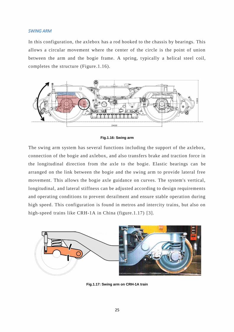
SWING ARM
In this configuration, the axlebox has a rod hooked to the chassis by bearings. This
allows a circular movement where the center of the circle is the point of union
between the arm and the bogie frame. A spring, typically a helical steel coil,
completes the structure (Figure.1.16).
Fig.1.16: Swing arm
The swing arm system has several functions including the support of the axlebox,
connection of the bogie and axlebox, and also transfers brake and traction force in
the longitudinal direction from the axle to the bogie. Elastic bearings can be
arranged on the link between the bogie and the swing arm to provide lateral free
movement. This allows the bogie axle guidance on curves. The system's vertical,
longitudinal, and lateral stiffness can be adjusted according to design requirements
and operating conditions to prevent derailment and ensure stable operation during
high speed. This configuration is found in metros and intercity trains, but also on
high-speed trains like CRH-1A in China (figure.1.17) [3].
Fig.1.17: Swing arm on CRH-1A train

26
HORIZONTAL LEAF SPRINGS
In this configuration, a horizontal leaf spring connects the axlebox and the bogie.
The idea is very similar as the swing arm system, but instead of a ro d. There is a
plane horizontal leaf which is linked also to the axlebox, it is not a part of it
(Figure.1.18). The connection of the steel leaf in both extremes is made by rubber
elements allowing yaw movement of the leaf and consequently, lateral movement
of the axlebox. It is another system to provide axle guidance to the bogie.
Fig.1.18: Horizontal leaf springs
Two parallel horizontal leaf springs instead of one is al so a possibility to guide
the axlebox. Again, the extremes of the two pairs of leaves are connected by rubber
bushings. This arrangement is used in the MD-522 by Bombardier [3] which is
used in the ICE (German High-speed trains) trailer bogies (Figure.1.19).
Fig.1.19: MD-522 Bogies by Bombardier
27
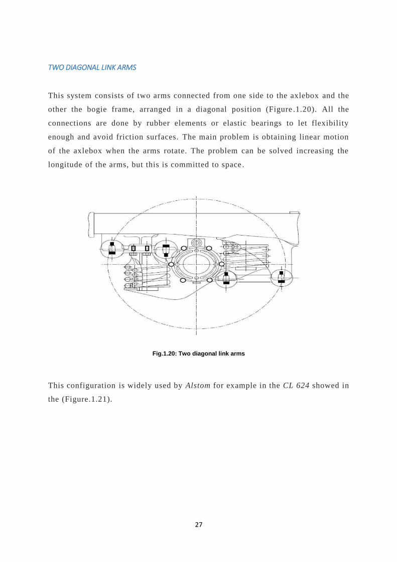
TWO DIAGONAL LINK ARMS
This system consists of two arms connected from one side to the axlebox and the
other the bogie frame, arranged in a diagonal position (Figure .1.20). All the
connections are done by rubber elements or elastic bearings to let flexibility
enough and avoid friction surfaces. The main problem is obtaining linear motion
of the axlebox when the arms rotate. The problem can be solved increasing the
longitude of the arms, but this is committed to space .
Fig.1.20: Two diagonal link arms
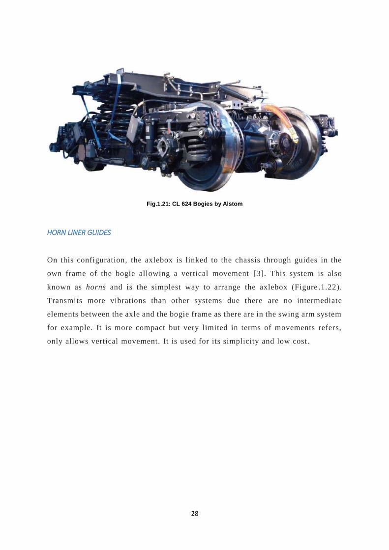
This configuration is widely used by Alstom for example in the CL 624 showed in
the (Figure.1.21).
28
Fig.1.21: CL 624 Bogies by Alstom
HORN LINER GUIDES
On this configuration, the axlebox is linked to the chassis through guides in the
own frame of the bogie allowing a vertical movement [3]. This system is also
known as horns and is the simplest way to arrange the axlebox (Figure .1.22).
Transmits more vibrations than other systems due there are no intermediate
elements between the axle and the bogie frame as there are in the swing arm system
for example. It is more compact but very limited in terms of movements refers,
only allows vertical movement. It is used for its simplicity and low cost .
29
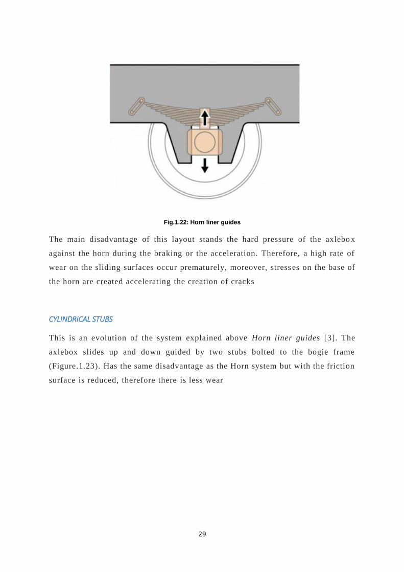
Fig.1.22: Horn liner guides
The main disadvantage of this layout stands the hard pressure of the axlebo x
against the horn during the braking or the acceleration. Therefore, a high rate of
wear on the sliding surfaces occur prematurely, moreover, stress es on the base of
the horn are created accelerating the creation of cracks
CYLINDRICAL STUBS
This is an evolution of the system explained above Horn liner guides [3]. The
axlebox slides up and down guided by two stubs bolted to the bogie frame
(Figure.1.23). Has the same disadvantage as the Horn system but with the friction
surface is reduced, therefore there is less wear

30
Fig.1.23: Cylindrical stubs
DAMPERS
The function of the damping elements is to absorb the oscillations produced by the
elastic suspension elements in the shortest possible time. Dampers absorb the
kinetic energy that is transmitted to the suspended mass and reduce the time in
which the wheel-rail adhesion varies due to the oscillations produced by the elastic
elements. They also break the oscillations produced in the suspended mass and in
the non-suspended mass. Dampers aim to provide the necessary comfort to the
passengers of the vehicle and limit the carbody movements.
Dampers can be classified into two groups: friction dampers and hydraulic
dampers:
• Friction dampers
• Hydraulic dampers
The friction dampers (Figure.1.24) the simplest ones but widely used on freight
vehicle or on bogies where the comfort is not essential

31
Fig.1.24: Friction dampers
Principal problem is that the damper starts working when the friction force is
exceeded, so the vehicle starts from an initial situation of blocked suspension.
Once the friction force is overcome, the damping force decreases with the speed
instead of increasing with it. In addition, continuous maintenance is necessary due
to the wear and tear suffered.
Hydraulic dampers (Figure.1.25) are the ones that use the viscosity of a fluid or
the compressibility of a gas to absorb the kinetic energy. There are basically two
different hydraulic dampers, monotube and double tube shock absorbers being the
second the most common for their best behavior. Hydraulic dampers are the most
common shock absorbers used on passenger bogies. Those can be used in both
primary and secondary suspension. Dampers arranged in parallel to the primary
suspension system ensure an optimal vibration and sound decoupling. This
solution is extended used in Siemens bogies for passengers like the SF 200.
Hydraulic dampers are also used to dampen the yaw and the tilting, also the axle
guidance (lateral movement) if the bogie is provided with it.

32
Fig.1.25: Hydraulic dampers
The correct usage of dampers is relevant to obtain a good comfort in the carbody,
that’s why many arrangements are avai lable on the market in the sense of getting
specific properties according to demand. For example, the SF 600 made by
Siemens, which is defined as a high-comfort bogie for passenger’s train, has a yaw
damper system fitted with hydraulic dampers, which can be automatically
activated depending on the vehicle speed to improve the stability of the carbody
Nevertheless, using an active stabilization of the wheelsets negates the need for
yaw dampers between bogie and carbody, which, in the case of conventional bogies
are required to stabilize the sinusoidal movement of the bogie. Furthermore, lower
weight designs are possible due to potential elimination of intervehicle dampers,
that means less material required.
E. BOGIE FRAME SHAPE
The bogie frame is the bogie chassis, where all the components are linked. There
is not a specific design or shape; it changes depending on the demands of each
33
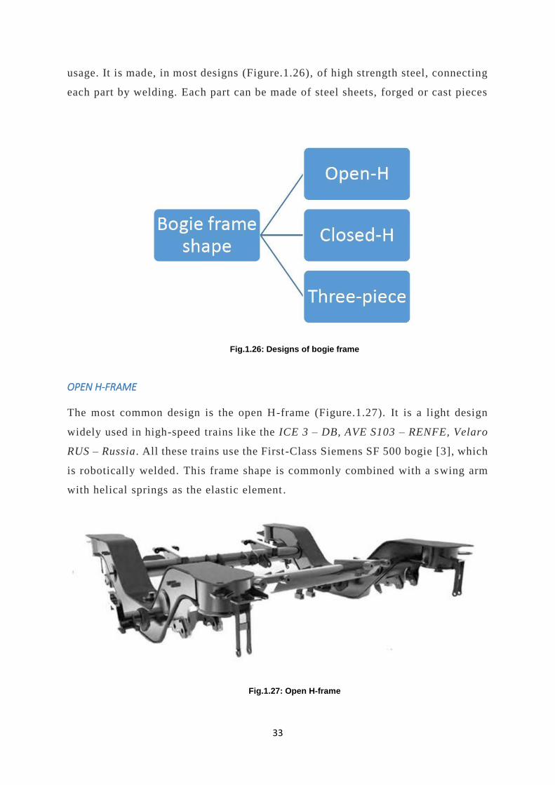
usage. It is made, in most designs (Figure.1.26), of high strength steel, connecting
each part by welding. Each part can be made of steel sheets, forged or cast pieces
Fig.1.26: Designs of bogie frame
OPEN H-FRAME
The most common design is the open H-frame (Figure.1.27). It is a light design
widely used in high-speed trains like the ICE 3 – DB, AVE S103 – RENFE, Velaro
RUS – Russia. All these trains use the First-Class Siemens SF 500 bogie [3], which
is robotically welded. This frame shape is commonly combined with a swing arm
with helical springs as the elastic element .
Fig.1.27: Open H-frame

34
The bearings can be located inboard with the bogie frame lying between the wheels
as shown in the lower image of the Figure.1.28, or outboard, keeping the wheels
in the inner part, top image of the Figure.1.28. Inboard bearings make the frame
lighter and more compact. This last configuration is used on regional passenger
trains and trams whose modest travel speed is unlikely to result in bearing failure
Fig.1.28: External & Internal Open H-frame
CLOSED H-FRAME
There exist also a closed H-frame that links the extremes of the H with a bolster
(Figure.1.29). This provides more torsional resistance, consequently, it has a
higher weight. This bogie frame is found on locomotives li ke the CL 622 from
Alstom. However, it is also rarely found on bogies for high-speed trains like the
SF 500 DSW from Siemens [3].
35
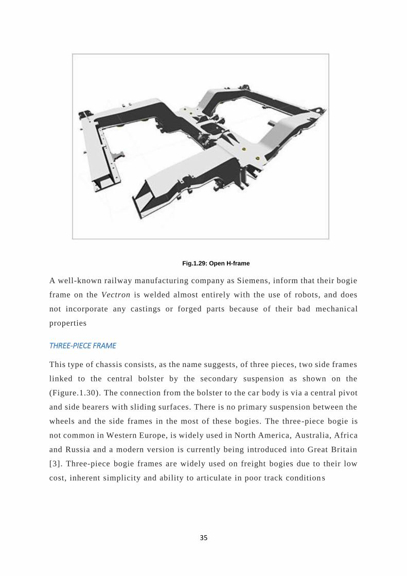
Fig.1.29: Open H-frame
A well-known railway manufacturing company as Siemens, inform that their bogie
frame on the Vectron is welded almost entirely with the use of robots, and does
not incorporate any castings or forged parts because of their bad mechanical
properties
THREE-PIECE FRAME
This type of chassis consists, as the name suggests, of three pieces, two side frames
linked to the central bolster by the secondary suspension as shown on the
(Figure.1.30). The connection from the bolster to the car body is via a central pivot
and side bearers with sliding surfaces. There is no primary suspension between the
wheels and the side frames in the most of these bogies. The three-piece bogie is
not common in Western Europe, is widely used in North America, Australia, Africa
and Russia and a modern version is currently being introduced into Great Britain
[3]. Three-piece bogie frames are widely used on freight bogies due to their low
cost, inherent simplicity and ability to articulate in poor track condition s

36
Fig.1.30: Three-piece frame

37
F. BRAKING SYSTEM
The principal function of the braking system is to reduce the spe ed of the train.
The weight, axle load and maximum speed are decisive parameters when choosing
one of these systems [3]. Braking can be achieved by the systems explained in this
subchapter which are classified in the (Figure.1.31).
Fig.1.31: Classification of braking system
TREAD BRAKES
Mostly used in non-tractive units, this brake uses the friction between a brake shoe
and the running surface of the wheel to create braking force. The wheel must be
designed to evacuate the heat and avoid thermal overst ress. The main problem of
this system is the considerable wear that occurs on the wheel. Over the time this
system has been replaced by disc brakes, however, these braking systems still used
in freight bogies [3].

38
DISC BRAKE
The braking effect is created by the friction of the brake shoe on the brake disc
(Figure.1.32) [3].
Fig.1.32: Disc brake
There is produced a transformation of the energy into heat and it is removed via
cooling fins. The most common designs are ventilated axle -mounted brake discs.
This system is the most common braking system used in all the bogies due to the
simplicity and good braking power which can be increased just adding more discs
in the same axle as needed Disc brakes can also be mounted on the inner part of
the wheel saving space on the axle box (Figure.1.33).The system is called wheel-
mounted brake discs. These are usually low-maintenance disc to reduce the life
cycle costs.
Fig.1.33: Wheel-mounted brake discs
39
ELECTRO-DYNAMIC BRAKE
This system consists on using an electric traction motor as a generator when
slowing the vehicle, it is understood that is a brake for electric tractive units. The
drive motor switches on and turns generators during the braking, transforming
kinetic energy of the train into electrical energy. Th is is a wear-free braking
system and it’s very effective at high speeds. It is assumed that the motor bogies
integrate this type of brakes [3].
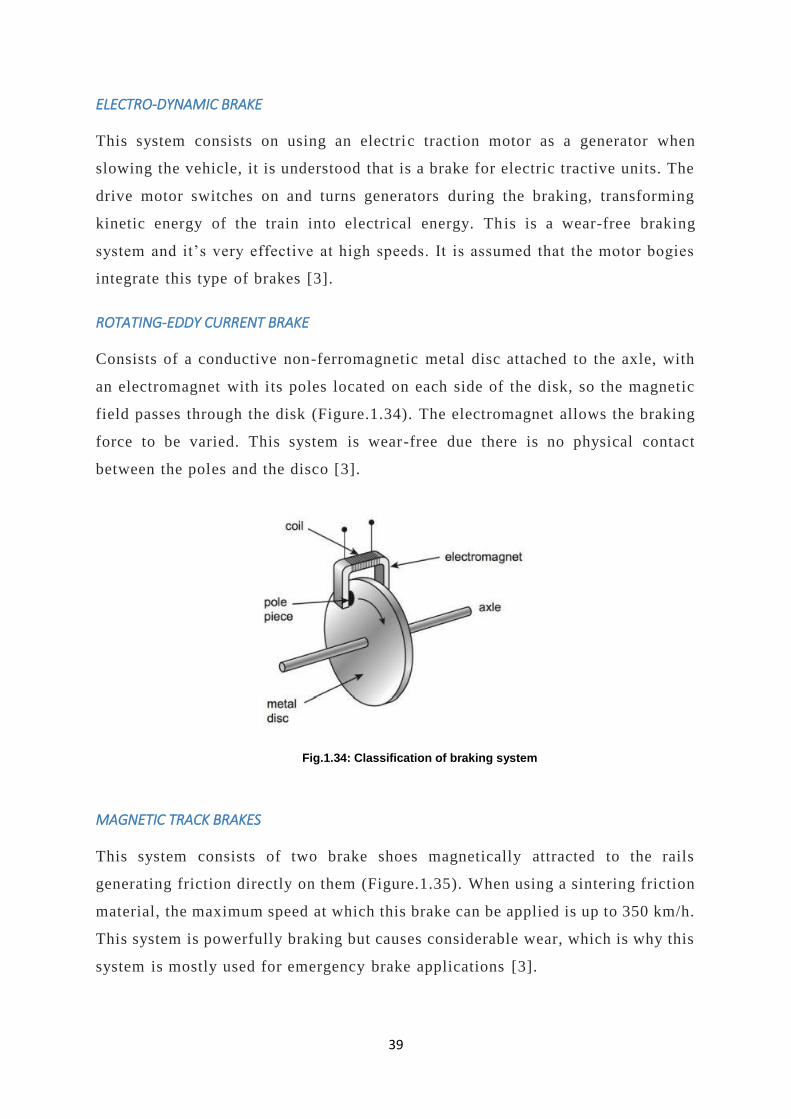
ROTATING-EDDY CURRENT BRAKE
Consists of a conductive non-ferromagnetic metal disc attached to the axle, with
an electromagnet with its poles located on each side of the disk, so the magnetic
field passes through the disk (Figure.1.34). The electromagnet allows the braking
force to be varied. This system is wear-free due there is no physical contact
between the poles and the disco [3].
Fig.1.34: Classification of braking system
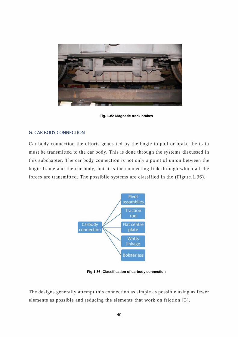
MAGNETIC TRACK BRAKES
This system consists of two brake shoes magnetically attracted to the rails
generating friction directly on them (Figure.1.35). When using a sintering friction
material, the maximum speed at which this brake can be applied is up to 350 km/h.
This system is powerfully braking but causes considerable wear, which is why this
system is mostly used for emergency brake applications [3].
40
Fig.1.35: Magnetic track brakes
G. CAR BODY CONNECTION
Car body connection the efforts generated by the bogie to pull or brake the train
must be transmitted to the car body. This is done through the systems discussed in
this subchapter. The car body connection is not only a point of union between the
bogie frame and the car body, but it is the connecting link through which all the
forces are transmitted. The possibile systems are classified in the (Figure.1.36).
Fig.1.36: Classification of carbody connection
The designs generally attempt this connection as simple as possible using as fewer
elements as possible and reducing the elements that work on friction [3].
41
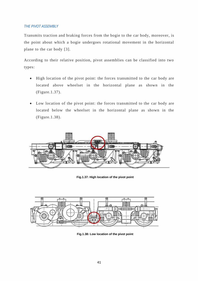
THE PIVOT ASSEMBLY
Transmits traction and braking forces from the bogie to the car body, moreover, is
the point about which a bogie undergoes rotational movement in the horizontal
plane to the car body [3].
According to their relative position, pivot assemblies can be classified into two
types:
• High location of the pivot point: the forces transmitted to the car body are
located above wheelset in the horizontal plane as shown in the
(Figure.1.37).
• Low location of the pivot point: the forces transmitted to the car body are
located below the wheelset in the horizontal plane as shown in the
(Figure.1.38).
Fig.1.37: High location of the pivot point
Fig.1.38: Low location of the pivot point

42
The low location of pivot point achieves higher values of tractive and brake efforts
on a bogie than another with the same design but a high pivot point. Pivot
assemblies can be designed with additional gaps that allow some small motion in
the horizontal plane. The ones with spherical joints allow the bogie to carry out a
rotational movement [3]. In addition, these can have movement in the vertical
plane and partial displacement in the horizontal plane. From the design point of
view, the pivot assembly consists of a pin rigidly fixed to the bogie frame on one
end, while, on the other end, a pin is inserted in the pivot yoke which is fixed to
the frame of the bogie or the bolster.
The advantages of a rigid pivot are the simplicity of their design and low-cost
manufacturing. This system allows lateral motions, therefore, have better
dynamics in comparison with rigid joints. In addition, this with spherical joints
can provide improved dynamic behavior for a traction bogie in comparison to other
designs.
A disadvantage are the clearances in longitudinal and lateral directions this system
has. Nevertheless, this design provides enough ride quality only for bogies having
low lateral stiffness of the secondary suspension [3].
FLAT CENTER PLATE
It is the most common connection for low speed and freight bogies. Consist of a
plate in charge of transmitting the weight of the bogie and both lateral and
longitudinal forces. It is normally located over the bolster , fitted in a crown
bearing (Figure.1.39). A pin pivot on the center always secures the structure. The
pin pivot has clearances on the yoke thus only provides emergency restraint. The
center plate allows the bogie to rotate in curves and creates a friction torque that
resists bogie rotation, therefore, the circular center plate provides a connection
between the bogie and the car body in all directions. This arrangem ent to join the
car body and the bogie frame is the simplest and low cost [3]. Logically it
has disadvantages, the most significant is that the rotary movement occurs
under a high contact pressure and, therefore, the surfaces are subject to
significant wear. On modern designs, it is being used a flat central plate
43
combined with elastic side supports that resist the rolling motion of the body
and reduce the load on the central plate
Fig.1.39: Flat center plate
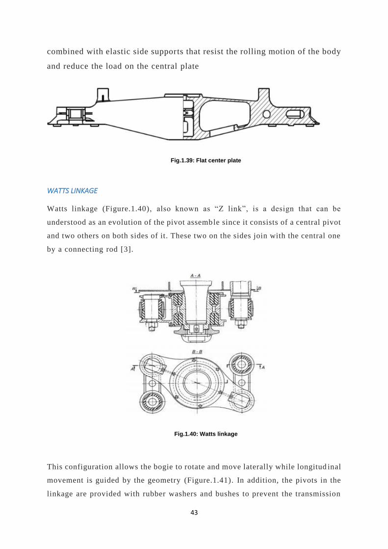
WATTS LINKAGE
Watts linkage (Figure.1.40), also known as “Z link”, is a design that can be
understood as an evolution of the pivot assemble since it consists of a central pivot
and two others on both sides of it. These two on the sides join with the central one
by a connecting rod [3].
Fig.1.40: Watts linkage
This configuration allows the bogie to rotate and move laterally while longitud inal
movement is guided by the geometry (Figure.1.41). In addition, the pivots in the
linkage are provided with rubber washers and bushes to prevent the transmission

44
of high frequency vibrations through the mechanism and improve the driving
comfort
Fig.1.41: Watts linkage configuration
BOLSTER LESS CONNECTION
A typical bogie design has a bolster joining transversely the springs of the
secondary suspension from one side to the other of the bogie frame. In the middle
of the bolster, there is the connect ion between the bogie and the car body. In the
bolster less designs, this bolster is missed and the link between the bogie and the
body rests only on the springs and a center pivot to transmit the forces. The bogie
rotates under the car body using the flexibility of secondary suspension. This
requires that the suspension used allows both longitudinal and lateral movements
for the correct turning of the bogie. Such requirement is solved with airsprings or
flexi-coil springs [3].
This design should use yaw dampers fitted longitudinally between the bogie and
the carbody to assure stability in a straight line.
TILTING
The tilting trains arise from the need to reduce the centrifugal forces in curves at high
speed [3]. This force pushes the passenger toward outside of the curve, hence comfort
is reduced. To solve this problem, some trains are equipped with a hydraulic or

45
electric system that makes the carbody tilt to the side where the center of the curve
(Figure.1.42).
Fig.1.42: Watts linkage
A tilting system (Figure.1.43) simulates a cant effect in railways which do not
have, thus a train can drive through places where initially were not designed for
high-speed. Even if the railway track is equipped with a cant, may not enough for
a high-speed train to run on it, hence the inclination helps to improve comfort and
drive faster.
An example of a bogie that uses a tilting system, is the CL 624 produced by Alstom
and used by RENFE or Trenitalia. This bogie is used in high-speed trains with an
operation speed around 225-250 km/h. The manufacturer Alstom specifies that

46
“has an active hydraulic tilting system (+/ - 8º) to enable to do high-speed curves
on conventional lines”.
There are four ways to tilt the carbody; two with no bolster, one just elevates the
secondary suspension and let the carbody naturally swings outwards the curve.
The other way is to actuate directly to the secondary suspension to make it tilt, for
example, applying differential control to the air springs. The other two systems
that use a bolster are the most complicated but also most effective tilting systems.
They are differentiated because one has the bolster above the secondary suspension
and the other below, this last avoids the increasing of the curving forces, and this is
probably the most common of all schemes. These two last are active ways to tilt in
the sense on there are arranged actuators (hydraulics or electrics) that force the car
body to tilt.
Tilting systems for high-speed trains is widely used due to their comfort gain. In
Japan for example, a passive system is used, in Italy, Pendolino trains have an active
control system, in Spain a completely different passive system had been developed
for the Talgo, however, in France and Germany, the high-speed lines are being built
on new alignments that don’t justify the expense and complication of tilt technology
.
Fig.1.43: Classification of tilting

47
WHEELSET STEERING
The steering is the capacity that the bogies have on the wheelset to adopt a radial
position in curves (Figure.1.44). This brings a significant decrease of flange wear
“10 time wear reduction”and lower track forces that will prolong the life of the
track and postpone the need for rail replacement. It prov ides a better behavior on
sharp curves, on a tram railway for example. Finally, the curve squeal noise is
eliminated or partially eliminated.
Fig.1.44: Steering
There are three different ways to get steering of the wheelset. The first is the one
that gets the yaw of the wheelset through the interaction between the rail and the
wheel. The second system, the yaw angles of the wheelsets are determined by the
angle of the bogie relative to the vehicle body, the wheelsets are forced to get
radial position due to the linkages between the wheelset and the vehicle body. This
second system has been used successfully on the Japanese Railways Hokkaido
Series 283 [3] passenger diesel motor units, where tests have shown that it reduces
48
lateral forces on the rail by a half or more. The last system integrates sensors and
actuators, either hydraulic or electric, that force the axlebox to adopt radial
position.
This is the most complicated system, but also the most effective . The two first
systems are passive ways of self-steering due there is any actuator that controls
the yaw of the wheelset.
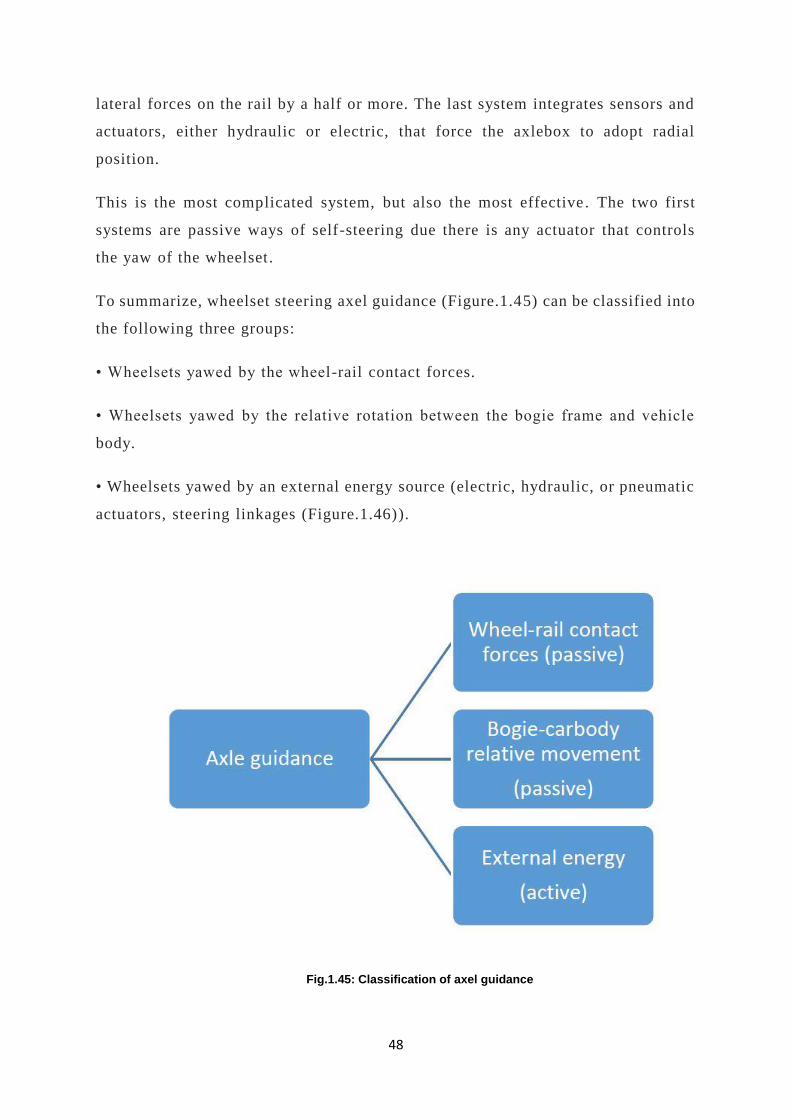
To summarize, wheelset steering axel guidance (Figure.1.45) can be classified into
the following three groups:
• Wheelsets yawed by the wheel-rail contact forces.
• Wheelsets yawed by the relative rotation between the bogie frame and vehicle
body.
• Wheelsets yawed by an external energy source (electric, hydraulic, or pneumatic
actuators, steering linkages (Figure.1.46)).
Fig.1.45: Classification of axel guidance

49
Fig.1.46: Steering linkages & Actuator
To understand how the axle can have yaw freedom to adopt radial position, the
(Figure.1.47) explains four different systems. The axlebox yaw must be
compatible with the primary suspension, which is joining the axlebox to the bogie
frame, hence the suspension must provide freedom in lateral and longitudinal
directions. This is not achieved by all the suspensions. To provide a bogie with
axle guidance, the selected suspension system should allow the lateral and
longitudinal displacement [3].

50
Fig.1.47: different systems of an axle
51
2 IMPACTS OF INNOVATIVE RUNNING
GEAR WITH COMPOSITE MATERIAL
2.1 OVERVIEW OF A SINGLE AXEL RUNNING GEAR
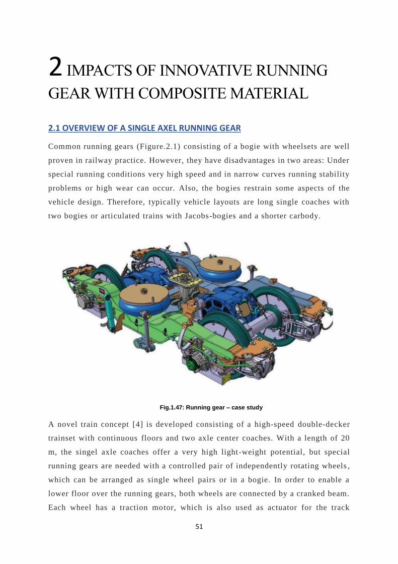
Common running gears (Figure.2.1) consisting of a bogie with wheelsets are well
proven in railway practice. However, they have disadvantages in two areas: Under
special running conditions very high speed and in narrow curves running stability
problems or high wear can occur. Also, the bogies restrain some aspects of the
vehicle design. Therefore, typically vehicle layouts are long single coaches with
two bogies or articulated trains with Jacobs-bogies and a shorter carbody.
Fig.1.47: Running gear – case study
A novel train concept [4] is developed consisting of a high-speed double-decker
trainset with continuous floors and two axle center coaches. With a length of 20
m, the singel axle coaches offer a very high light-weight potential, but special
running gears are needed with a controlled pair of independently rotating wheels ,
which can be arranged as single wheel pairs or in a bogie. In order to enable a
lower floor over the running gears, both wheels are connected by a cranked beam.
Each wheel has a traction motor, which is also used as actuator for the track

52
guiding and radial steering in curves. This mechatronic running gear should offer
a better running performance than a conventional running gear under all operation
conditions in combination with a low maintenance effort.
The challenges for the development of a mechatronic track guidance system are to
find a robust sensor to detect the current lateral position of the wheels relative to
the track, which can be placed in a real running gear, a robust control algorithm,
which is able to adjust itself to alternating operation conditions and a powerful
actuator to realize the commands of the control system.
The basic idea of the novel mechatronic running gear concept consists of
independently rotating wheels with a mechatronic guidance system to overcome
the disadvantages of conventional wheelsets under certain operating conditions.
At most operation conditions a conventional wheelset offers a good guidance
quality, but at very high speed and in narrow curves problems can occur on
vehicles with conventional wheelsets, for instance instability (high speed) or high
wear and vibrations (curves). In principle, the problems should disappear by using
independently rotating wheels (IRW).
Otherwise, vehicles with independently rotating wheels – without an active
guidance system – often need a higher maintenance effort to ensure low wear at
the wheels, because of the reduced centering effect of independently rotating
wheels.
The aim is the development of a running gear, which offers gear under all
operation conditions in combination with a low maintenance effort a better running
performance than a conventional running. This means a lower emission level of
vibrations to the ground and the air as well as less friction at cu rves and therefore
a lower need of traction energy. Additionally, the running gear concept enables
more comfortable train concepts such as low floor trams or double deck trains with
two continuous decks. The principle is applicable to bogies as well as running
gears with a single pair of wheels .
These features are preconditions for the realization of “Next generation Train” -
NGT, (Figure.2.1). The NGT is a research project and was started in 2007 [4].
Eight institutes are engaged in different rail specific topics such as aerodynamics,
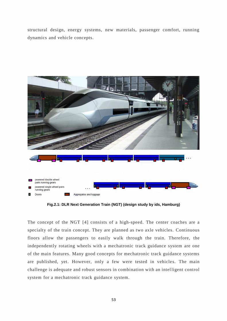
53
structural design, energy systems, new materials, passenger comfort, running
dynamics and vehicle concepts.
Fig.2.1: DLR Next Generation Train (NGT) (design study by ids, Hamburg)
The concept of the NGT [4] consists of a high-speed. The center coaches are a
specialty of the train concept. They are planned as two axle vehicles. Continuous
floors allow the passengers to easily walk through the train. Therefore, the
independently rotating wheels with a mechatronic track guidance system are one
of the main features. Many good concepts for mechatronic track guidance systems
are published, yet. However, only a few were tested in vehicles. The main
challenge is adequate and robust sensors in combination with an intel ligent control
system for a mechatronic track guidance system.

54
Especially in a high-speed train, an active track guidance system is a very
ambitious challenge and requires high demands of the sensor and control system.
For instance, the sensor must be able to identify the position of the wheels relative
to the track and the control system must be fast enough to avoid flange contact
even at highly disturbed tracks at high speed.
At the end this novel mechatronic running gear will increase the competitivenes s
and acceptance of the railway by a cost -effective and low emission running gear.
The mechatronic wheel pairs, which are an enhancement of the mechatronic
wheelset, are the main issue of the running gear. the following classification of
the concepts for steering of IRW, is suggested [4]:
• Driven independently rotating wheels (DIRW)
• Directly steered wheels (DSW)
• NGT CONCEPT
Fig. 2.2: streeing principles for independently rotating wheels
The concept of the driven independently rotating wheels (Fig.2.2) consists of two
wheels mounted at a frame. The wheels are steered by applying differential
traction or braking torques on both wheels. The springs between the frame and the
carbody or a bogie frame allow a limited rotational movement around the vertical
axis. The directly steered wheels have a coupled rotational degree of freedom. The
wheels can be steered by applying differential traction / braking torques on both
wheels or by an actuator.
55
The novel NGT concept is a combination of both (Fig.2.2): we think that both
wheels need a tough connection with a beam without any joints except for the
wheel rotation. The beam can have a U-shape with respect to the low floor. The
aim of the concept is to ensure the same running quality compared to wheelsets
and also to improve the running behavior in operation conditions, in which a
conventional wheelset reaches its limits – in particular:
• At (very) high speed large yaw dampers are necessary for the stability of
the hunting mode.
• In curves with (very) small radius large creeps occur and produce the related
problems: wear, corrugation, noise and higher traction effort.
The traction motors of the independently rotating wheels are also used as a ctuator
for the track guidance of the wheel pairs and a radial steering in curves. Therefore,
each wheel pair can rotate around the vertical axis. Given that the rotation velocity
of each wheel is controlled and that the wheel pair is held in a radial posi tion, the
creep can be minimized by force controlling.
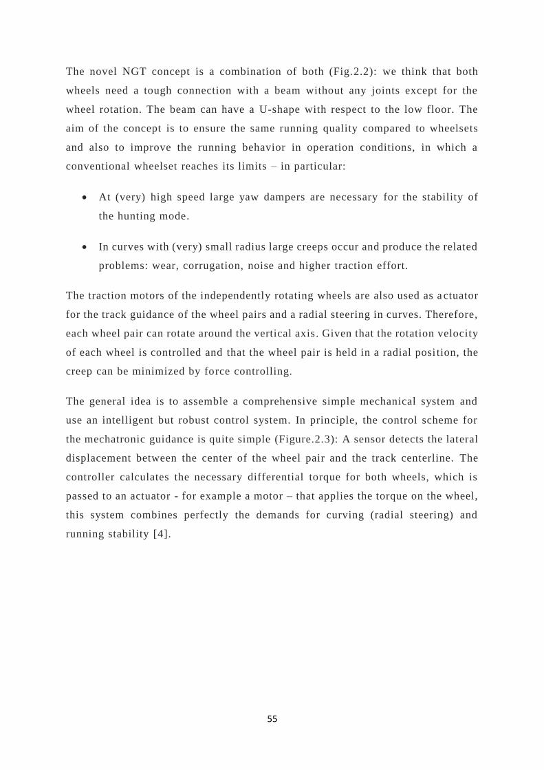
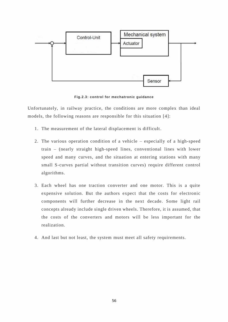
The general idea is to assemble a comprehensive simple mechanical system and
use an intelligent but robust control system. In principle, the control scheme for
the mechatronic guidance is quite simple (Figure.2.3): A sensor detects the lateral
displacement between the center of the wheel pair and the track centerline. The
controller calculates the necessary differential torque for both wheels, which is
passed to an actuator - for example a motor – that applies the torque on the wheel,
this system combines perfectly the demands for curving (radial steering) and
running stability [4].
56
Fig.2.3: control for mechatronic guidance
Unfortunately, in railway practice, the conditions are more complex than ideal
models, the following reasons are responsible for this situation [4]:
1. The measurement of the lateral displacement is difficult .
2. The various operation condition of a vehicle – especially of a high-speed
train – (nearly straight high-speed lines, conventional lines with lower
speed and many curves, and the situation at entering stations with many
small S-curves partial without transition curves) require different control
algorithms.
3. Each wheel has one traction converter and one motor. This is a quite
expensive solution. But the authors expect that the costs for electronic
components will further decrease in the next decade. Some light rail
concepts already include single driven wheels. Therefore, it is assumed, that
the costs of the converters and motors will be less important for the
realization.
4. And last but not least, the system must meet all safety requirements.

57
Fig.2.4: single axe running gear & Wheel module
Both wheels (1) in (Figure.2.4) of the running gear are connected by the cranked
beam (2). The primary springs (3) are stiff in vertical direction and softer in
horizontal direction. At present, the primary springs are only defined by their
stiffness. The traction motor (4) and the brake discs (5) are arranged outside the
wheels. Two levers (6) transfer the horizontal forces between the cranked beam
and the running gear frame (7) and define the center for rotation around the vertical
axis. Also actuated fiber-reinforced composite leaf springs are used for the
secondary suspension (8) [4].
2.2 REFERENCE CASE: ROME–CIVITACASTELLANA–VITERBO RAILWAY
Here we are analyzing a reference case with a conventional bogie -based vehicle
compared with a single-axel configuration using distinctive design material for
weight and energy consumption reduction and assuming advanced mechatronic.
The Rome–Civitacastellana–Viterbo railway is a light rail way line
connecting Rome, Italy, with Viterbo,[1] capital city of the Province of Viterbo.
The 102 km long line, also known in Rome as the Roma Nord line, after its
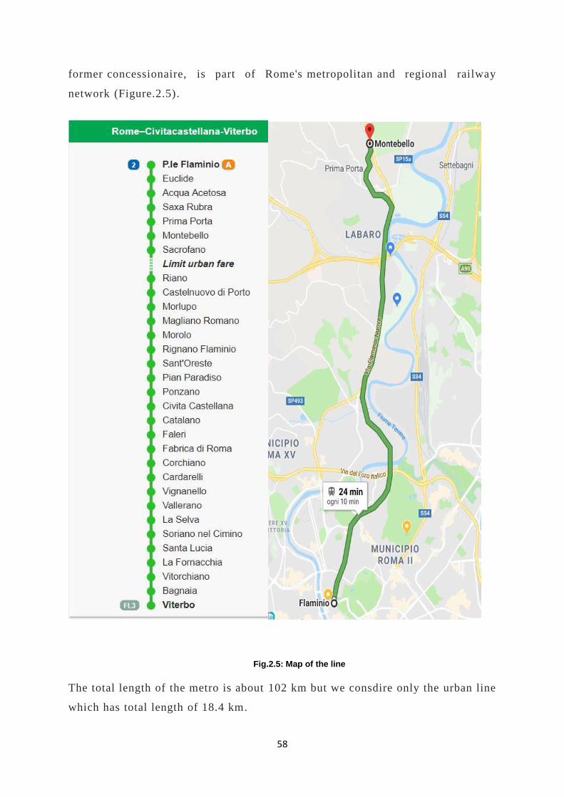
58
former concessionaire, is part of Rome's metropolitan and regional railway
network (Figure.2.5).
Fig.2.5: Map of the line
The total length of the metro is about 102 km but we consdire only the urban line
which has total length of 18.4 km.

59
There are 31 stops which 7 are urban and 24 extra urban and it takes about 24
minutes approximately for the round trip. Currently the rolling stock used is
Elettromotrice 310, terza generazione (Figure.2.6) by CostaRail and Alstom, the
rolling stock is consisting of three car body with conventional running gear.
Fig.2.6: Elettromotrice 310, terza generazione
60
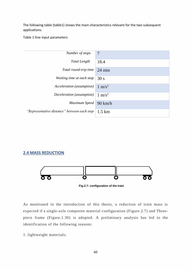
The following table (table1) shows the main characteristics relevant for the two subsequent
applications.
Table 1-line input parameters
Number of stops 7
Total Length
18.4
Total round-trip time 24 min
Waiting time at each stop 30 s
Acceleration (assumption) 1 m/s2
Deceleration (assumption) 1 m/s2
Maximum Speed 90 km/h
“Representative distance” between each stop 1.5 km
2.4 MASS REDUCTION
Fig.2.7: configuration of the train
As mentioned in the introduction of this thesis, a reduction of train mass is
expected if a single-axle composite material configuration (Figure.2.7) and Three-
piece frame (Figure.1.30) is adopted. A preliminary analysis has led to the
identification of the following reasons:
1. lightweight materials;
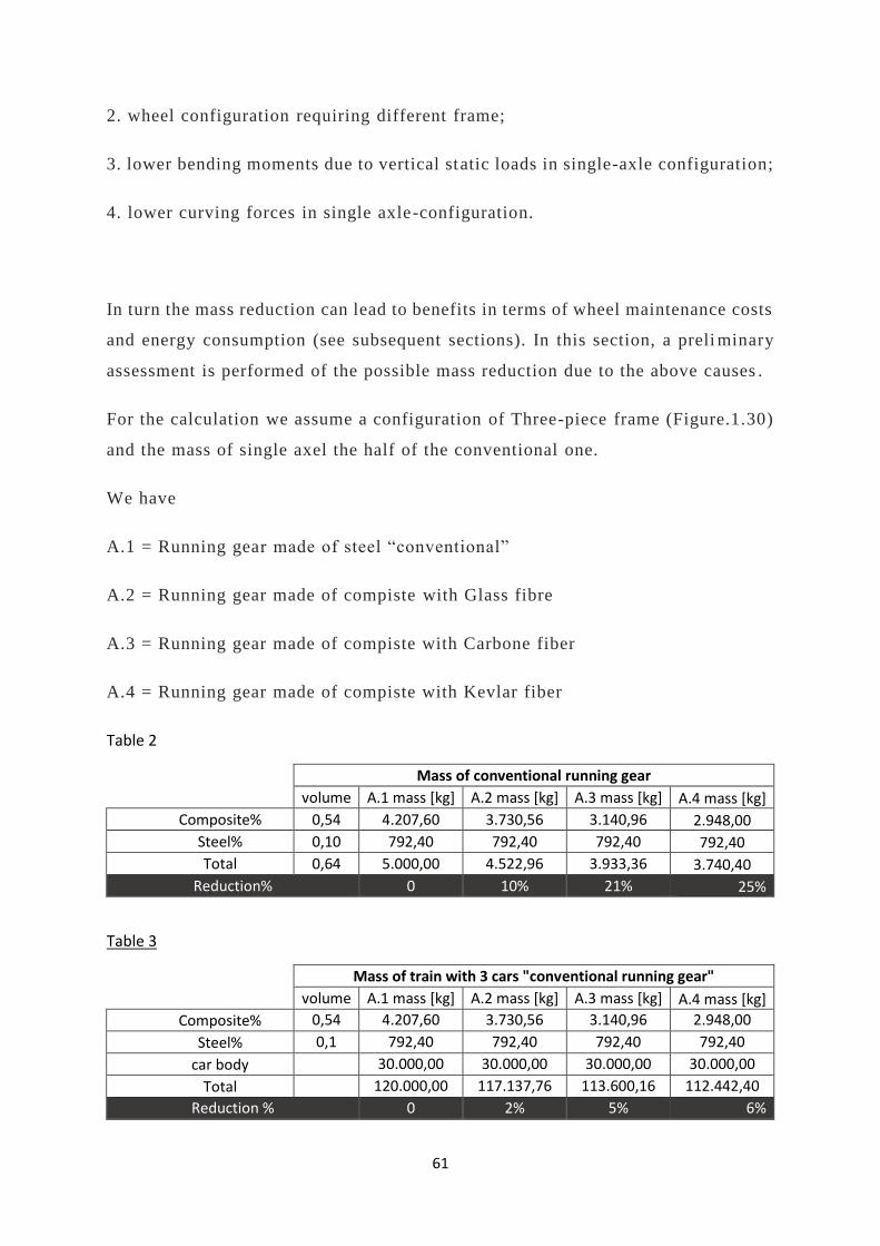
61
2. wheel configuration requiring different frame;
3. lower bending moments due to vertical static loads in single-axle configuration;
4. lower curving forces in single axle-configuration.
In turn the mass reduction can lead to benefits in terms of wheel maintenance costs
and energy consumption (see subsequent sections). In this section, a preli minary
assessment is performed of the possible mass reduction due to the above causes .
For the calculation we assume a configuration of Three-piece frame (Figure.1.30)
and the mass of single axel the half of the conventional one.
We have
A.1 = Running gear made of steel “conventional”
A.2 = Running gear made of compiste with Glass fibre
A.3 = Running gear made of compiste with Carbone fiber
A.4 = Running gear made of compiste with Kevlar fiber
Table 2
Mass of conventional running gear volume A.1 mass [kg] A.2 mass [kg] A.3 mass [kg] A.4 mass [kg]
Composite% 0,54 4.207,60 3.730,56 3.140,96 2.948,00
Steel% 0,10 792,40 792,40 792,40 792,40
Total 0,64 5.000,00 4.522,96 3.933,36 3.740,40
Reduction% 0 10% 21% 25%
Table 3
Mass of train with 3 cars "conventional running gear" volume A.1 mass [kg] A.2 mass [kg] A.3 mass [kg] A.4 mass [kg]
Composite% 0,54 4.207,60 3.730,56 3.140,96 2.948,00
Steel% 0,1 792,40 792,40 792,40 792,40
car body 30.000,00 30.000,00 30.000,00 30.000,00
Total 120.000,00 117.137,76 113.600,16 112.442,40
Reduction % 0 2% 5% 6%
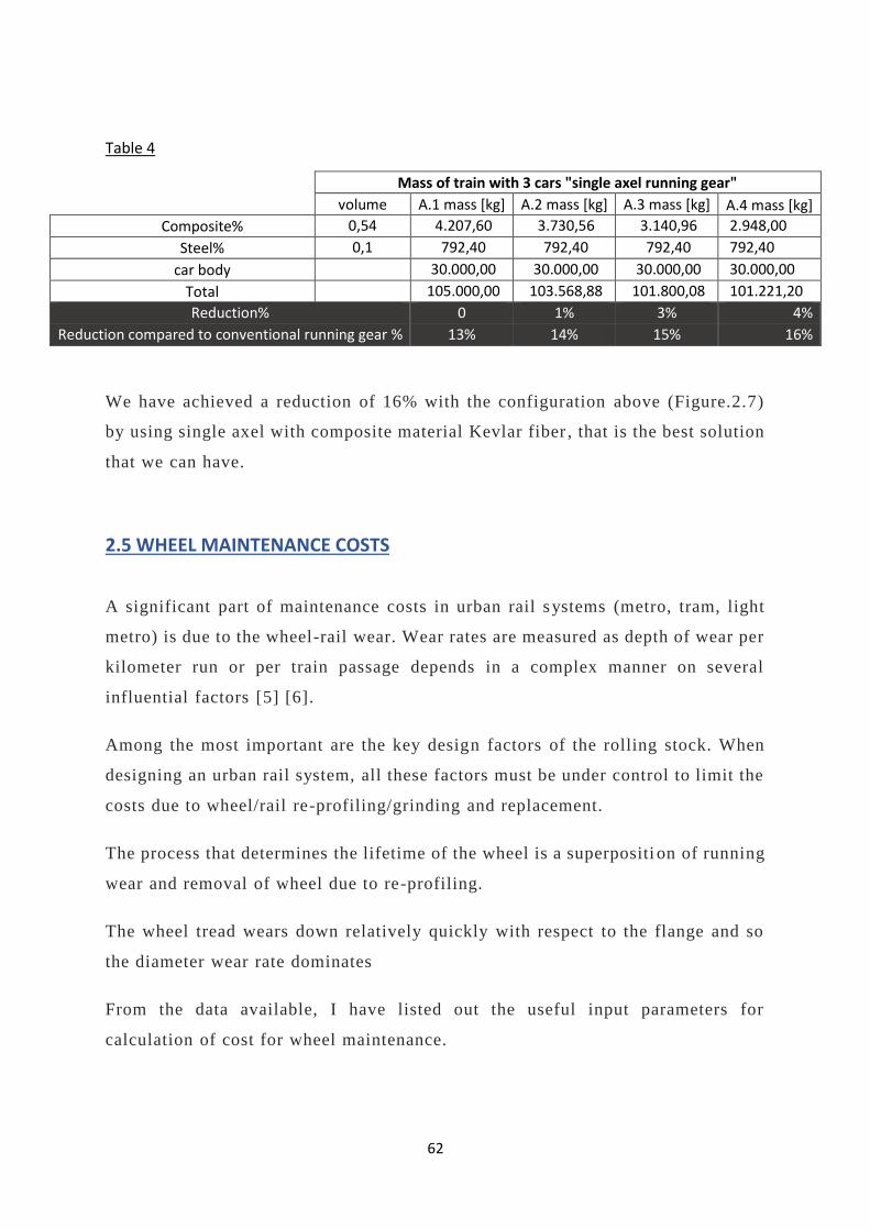
62
Table 4
Mass of train with 3 cars "single axel running gear" volume A.1 mass [kg] A.2 mass [kg] A.3 mass [kg] A.4 mass [kg]
Composite% 0,54 4.207,60 3.730,56 3.140,96 2.948,00
Steel% 0,1 792,40 792,40 792,40 792,40
car body 30.000,00 30.000,00 30.000,00 30.000,00
Total 105.000,00 103.568,88 101.800,08 101.221,20
Reduction% 0 1% 3% 4%
Reduction compared to conventional running gear % 13% 14% 15% 16%
We have achieved a reduction of 16% with the configuration above (Figure.2.7)
by using single axel with composite material Kevlar fiber , that is the best solution
that we can have.
2.5 WHEEL MAINTENANCE COSTS
A significant part of maintenance costs in urban rail systems (metro, tram, light
metro) is due to the wheel-rail wear. Wear rates are measured as depth of wear per
kilometer run or per train passage depends in a complex manner on several
influential factors [5] [6].
Among the most important are the key design factors of the rolling stock. When
designing an urban rail system, all these factors must be under control to limit the
costs due to wheel/rail re-profiling/grinding and replacement.
The process that determines the lifetime of the wheel is a superpositi on of running
wear and removal of wheel due to re-profiling.
The wheel tread wears down relatively quickly with respect to the flange and so
the diameter wear rate dominates
From the data available, I have listed out the useful input parameters for
calculation of cost for wheel maintenance.
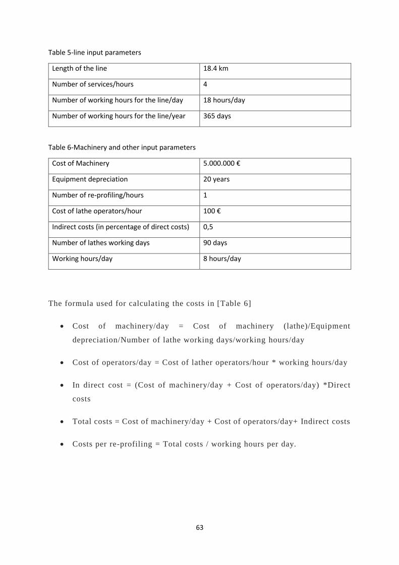
63
Table 5-line input parameters
Length of the line 18.4 km
Number of services/hours 4
Number of working hours for the line/day 18 hours/day
Number of working hours for the line/year 365 days
Table 6-Machinery and other input parameters
Cost of Machinery 5.000.000 €
Equipment depreciation 20 years
Number of re-profiling/hours 1
Cost of lathe operators/hour 100 €
Indirect costs (in percentage of direct costs) 0,5
Number of lathes working days 90 days
Working hours/day 8 hours/day
The formula used for calculating the costs in [Table 6]
• Cost of machinery/day = Cost of machinery (lathe)/Equipment
depreciation/Number of lathe working days/working hours/day
• Cost of operators/day = Cost of lather operators/hour * working hours/day
• In direct cost = (Cost of machinery/day + Cost of operators/day) *Direct
costs
• Total costs = Cost of machinery/day + Cost of operators/day+ Indirect costs
• Costs per re-profiling = Total costs / working hours per day.
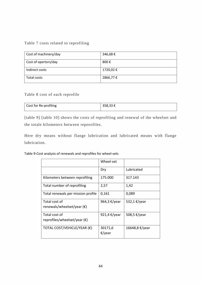
64
Table 7 costs related to reprofiling
Cost of machinery/day 346,68 €
Cost of opertors/day 800 €
Indirect costs 1720,02 €
Total costs 2866,77 €
Table 8 cost of each reprofile
Cost for Re-profiling 358,33 €
[table 9] [table 10] shows the costs of reprofiling and renewal of the wheelset and
the totale kilometers between reporofiles.
Here dry means without flange lubrication and lubricated means with flange
lubrication.
Table 9-Cost analysis of renewals and reprofiles for wheel-sets
Wheel-set
Dry Lubricated
Kilometers between reprofiling 175.000 317.143
Total number of reprofiling 2,57 1,42
Total renewals per mission profile 0,161 0,089
Total cost of
renewals/wheelset/year (€)
964,3 €/year 532,1 €/year
Total cost of
reprofiles/wheelset/year (€)
921,4 €/year 508,5 €/year
TOTAL COST/VEHICLE/YEAR (€) 30171,6
€/year
16648,8 €/year
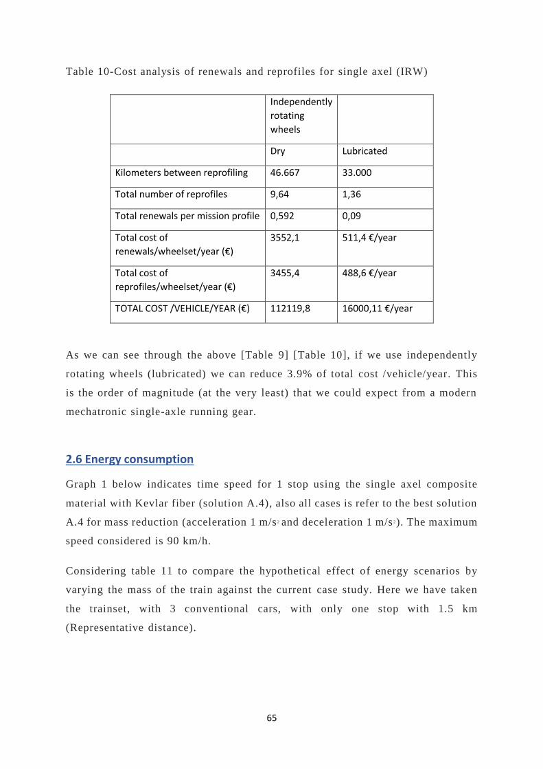
65
Table 10-Cost analysis of renewals and reprofiles for single axel (IRW)
Independently
rotating
wheels
Dry Lubricated
Kilometers between reprofiling 46.667 33.000
Total number of reprofiles 9,64 1,36
Total renewals per mission profile 0,592 0,09
Total cost of
renewals/wheelset/year (€)
3552,1 511,4 €/year
Total cost of
reprofiles/wheelset/year (€)
3455,4 488,6 €/year
TOTAL COST /VEHICLE/YEAR (€) 112119,8 16000,11 €/year
As we can see through the above [Table 9] [Table 10], if we use independently
rotating wheels (lubricated) we can reduce 3.9% of total cost /vehicle/year. This
is the order of magnitude (at the very least) that we could expect from a modern
mechatronic single-axle running gear.
2.6 Energy consumption
Graph 1 below indicates time speed for 1 stop using the single axel composite
material with Kevlar fiber (solution A.4), also all cases is refer to the best solution
A.4 for mass reduction (acceleration 1 m/s 2 and deceleration 1 m/s 2). The maximum
speed considered is 90 km/h.
Considering table 11 to compare the hypothetical effect of energy scenarios by
varying the mass of the train against the current case study. Here we have taken
the trainset, with 3 conventional cars, with only one stop with 1.5 km
(Representative distance).
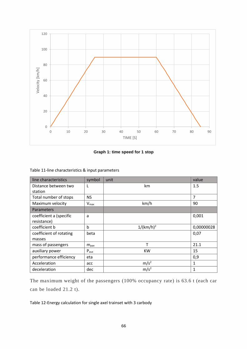
66
Graph 1: time speed for 1 stop
Table 11-line characteristics & input parameters
line characteristics symbol unit value
Distance between two station
L km 1.5
Total number of stops NS
7
Maximum velocity Vmax km/h 90
Parameters
coefficient a (specific resistance)
a
0,001
coefficient b b 1/(km/h)2 0,00000028
coefficient of rotating masses
beta
0,07
mass of passengers mpax T 21.1
auxiliary power Paux KW 15
performance efficiency eta
0,9
Acceleration acc m/s2 1
deceleration dec m/s2 1
The maximum weight of the passengers (100% occupancy rate) is 63.6 t (each car
can be loaded 21.2 t).
Table 12-Energy calculation for single axel trainset with 3 carbody
0
20
40
60
80
100
120
0 10 20 30 40 50 60 70 80 90
Vel
oci
ty [
km/h
]
TIME [S]

67
Case A.1 A.2 A.3 A.4
Energy calculation at starting [kJ]
46.774
46.449
46.048
45.917
Energy calculation at constant speed [kJ]
3.965
3.938
3.905
3.894
Energy for auxiliary [kJ] 1.725
1.725
1.725
1.725
Total energy consumption [kJ]
52.465
52.113
51.678
51.536
CASE 1: ENERGY CONSUMPTION WITH VARYING SPEED
In this case we are analyzing the energy consumption with speed variation.
Here the energy is calculated with full load for one stop.
Graph 2: speed versus Energy for 1 stop
0
10000
20000
30000
40000
50000
60000
0 20 40 60 80 100
Ener
gy c
on
sum
pti
on
(kJ)
Speed [km/h]

68
Graph 3: speed versus Energy for 7 stops
CASE 2: ENERGY CONSUMPTION WITH DISTANCE In the following, the variation of energy consumption with distance is analyzed.
Graph 4: Energy versus distance for 1 stop
0
50000
100000
150000
200000
250000
300000
350000
400000
0 20 40 60 80 100
Ener
gy c
on
sum
pti
on
[kJ]
Speed [km/h]
0
10000
20000
30000
40000
50000
60000
70000
0 0,5 1 1,5 2 2,5 3 3,5 4
Ener
gy c
on
sum
pti
on
[kJ]
Distance [km]
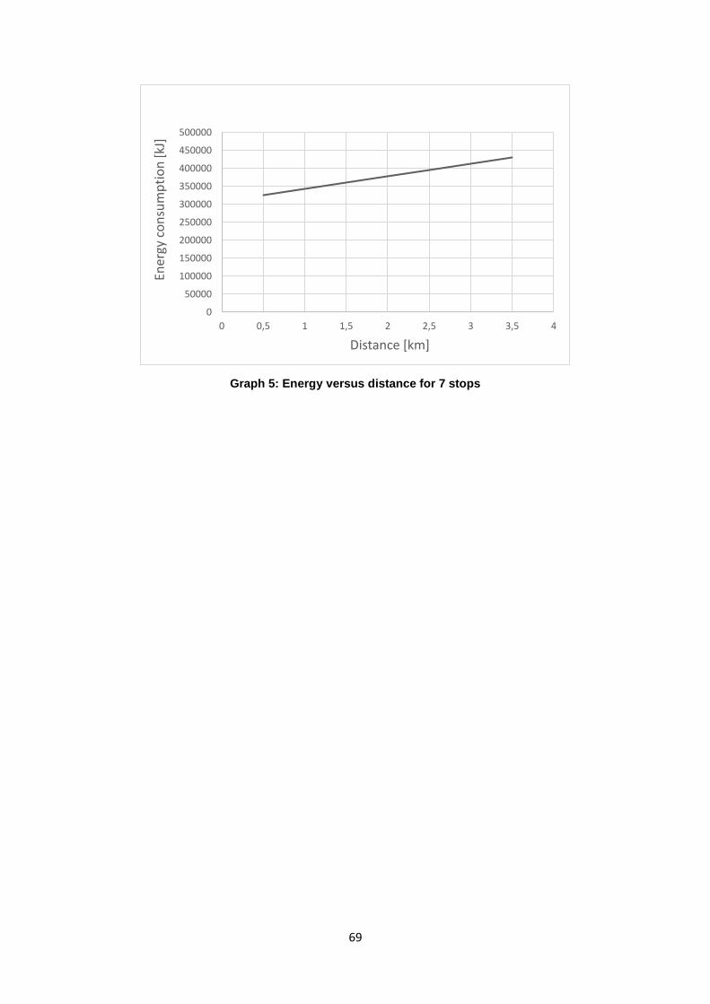
69
Graph 5: Energy versus distance for 7 stops
0
50000
100000
150000
200000
250000
300000
350000
400000
450000
500000
0 0,5 1 1,5 2 2,5 3 3,5 4
Ener
gy c
on
sum
pti
on
[kJ]
Distance [km]

70
CASE 3: ENERGY CONSUMPTION WITH PASSENGER OCCUPANCY RATE
In here we can see how the payload effects the energy consumption and, we can
see the approximate percentage of mass reduction and energy consumption
reduction.
Graph 6: Energy consumption reduction with passenger occupancy rate and mass reduction

71
CASE 4: ENERGY CONSUMPTION WITH AUXILIARY POWER
In our reference case we assumed the average auxiliary power as 15 kW.
Graph 7: Auxiliary power vs Energy consumption for 1 stop
Graph 8: Auxiliary power vs energy consumption for 7 stops
49500
50000
50500
51000
51500
52000
52500
53000
53500
0 5 10 15 20 25 30 35
Ener
gy c
on
sup
tio
n [k
J]
Ausiliary power [kw]
345000
350000
355000
360000
365000
370000
375000
0 5 10 15 20 25 30 35
Ener
gy c
on
sup
tio
n [k
J]
Ausiliary power [kw]

72
3 RELEVANT REGULATION AND
STANDARDIZATION DOCUMENTS
3.1 IMPORTANCE OF REGULATION AND STANDARDIZATION DOCUMENTS
Standards provide people and organizations with a basis for mutual understanding,
and are used as tools to facilitate communication, measurement, commerce and
manufacturing [7].
Standards are everywhere and play a key role in the economy, by:
• Facilitating business interaction;
• Enabling companies to comply with relevant laws and regulations ;
• Speeding up the introduction of innovative products to market ;
• Providing interoperability between new and existing products, services and
processes.
Standards form the basis for the introduction of modern technologies and
innovations, and ensure that products, components and services supplied by
different companies will be mutually compatible. However, they can also
introduce barriers to innovation.
In Europe, regulatory documents fall into a broad scope of rail-related legislation,
made up of Directives and Regulations, and so-called Technical Specifications for
Interoperability.
In the following, an analysis of the most relevant standardization documents is
presented, following the order of the topics described in the Shift2Rail
Programme.
73
3.2 CONDITION MONITORING / HEALTH MONITORING
In all industrial fields excessive costs are related to maintenance activities. The
excessive costs are related to the loss of productivity due to a poor availability of
assets regularly maintained. That is why there are research efforts dedicated to
improving condition monitoring/health monitoring as a basis for predictive
maintenance.
For the rail sector no standards were found for condition monitoring/ h ealth
monitoring. General standardization efforts in the United Stated on the other hand,
regards integrated system maintenance and goes along with :
• a standard for an easy transduction interface for sensors and actuators (IEEE
1451);
• a proposal of standardization for the architecture of condition-monitoring
systems (OSA-CBM);
• a proposal of standardization for the communication between different
condition-monitoring systems (MIMOSA)
A. ISEE (1451)
Due to the problems encountered by users during the activ ities of products
integration (transducer, sensors and actuators) of different vendors and their
network connection, it is necessary to adopt a standard for the hardware and
software interconnection level, to obtain the interoperability in the exchange and
in the use of information.
To develop a standard interface for intelligent sensors, the National Institute of
Standards and Technology (NIST), in cooperation with the Institute of Electrical
and Electronics Engineers (IEEE), has started to work on this o bjective since the
mid 90’s. This purpose is subsequently becoming the standard IEEE 1451, which
aims to achieve common interfaces to connect transducers towards systems based
on microprocessors and towards tools and field networks, avoiding that the
operation related to a network node (insertion/deletion) can influence the behavior
of the other nodes.
74
B. OSA-CBM
OSA-CBM is the acronym of Open System Architecture for Condition Based
Maintenance.
The mission of OSA-CBM organization states that the standard proposal should
cover the entire range of functions of a condition-based maintenance system, both
for hardware and software components. The proposed Condition -Based
Maintenance System is divided into seven levels (figure.3.1).
Level 1 Sensor Module: It provides sensors that return digitalized results or
transducers that return data. Signal module could be built following the standard
IEEE 1451.
Level 2 Signal Processing: The module receives signals and data from the sensor
module or other modules of signal processing. The output of signal processing
module includes sensor-data digitally filtered, frequency spectrum, signals of
virtual sensor. The signal processing module may consist of an AI-ESTATE, as
reported in IEEE 1232 standard.
Level 3 Condition Monitor: The condition-monitor level receives data from sensor
modules, signal processing modules and other condition-monitor modules. The
main goal of this level is to compare data with their expected values. The
condition-monitor level shall be also able to generate alerts based on operational
limits previously set. This latter can be a very useful function during development
of rapid failures.
Level 4 Health Monitoring: The module devoted to the assessment of the “status
of health” receives data from different condition-monitor modules or other
modules of assessment of the system conditions. The main goal of the condition
assessment module is to determine if the condition of the monitored
component/subsystem/system is degraded. The evaluation module shall be ab le to
generate diagnostic recordings and propose failure estimation. The diagnosis shall
be based on trends of the health status history, on operating status, workload and
maintenance history.
75
Level 5 Prognostics: The prognostic module shall be able to consider data from
all the previous levels. The main goal of the prognostic module is to compute the
future health status of an asset, considering its future profile of usage. The module
will report the future health status at a specified time or, alternative ly, the
remaining useful lifetime.
Level 6 Decision Support: The decision support module receives data from the
module of health status evaluation and the prognostic module. Its main goal is to
generate the recommended actions and the alternatives ones. Actions may be of
maintenance type but also related to how to run an asset until the current mission
is completed without the occurrence of breakage.
Level 7 Presentation: The presentation module must show the data coming from
all the previous modules. The most important levels of which present the data are
those related to Health Assessment, Prognostic and Decision Support, as well as
the alarms generated by the condition-monitor modules. The presentation module
can also can look further downwards and can be inserted also into a machine-
interface.

76
Fig.3.1: OSA-CBM Architecture

77
3.3 Materials and manufacturing processes
There are several standards for using the varied materials and different
manufacturing processes. Here are some of the standards:
• prEn-17084: This standard specifies the toxicity test on materials and
components of railway vehicles [13].
• EN 45545: The protection of passengers and staff is essentially based on
measures to: - prevent fires occurring due to technical faults and due to
equipment design or vehicle layout [14].
• EN 50125: This European Standard intends to define environmental
conditions within Europe. The scope of this European Standard covers the
definitions and ranges of the following parameters: Altitude, temperature,
humidity, air movement, rain, snow and hail, ice, solar radiation, lightning,
pollution for rolling stock and on-board equipment (mechanical,
electromechanical, electrical, electronic). This European Standard defines
interface conditions between the vehicle and its environment. The defined
environmental conditions are considered as normal in service [15].
• EN 16452:2015: This European Standard gives the requirements for the
design, dimensions, performance, and testing of a brake block (otherwise
known as brake shoe insert) that acts on the wheel tread as part of a tread
brake system. This European Standard contains the requirements for
interfacing the brake block with the rail vehicle, the testing procedures to
confirm that it satisfies the basic safety and technical interch angeability
requirements, the material control procedures to ensure product quality,
reliability and conformity and considers health and environmental needs
[16].
• EN 15085-1:2007+A1:2013: This series of standards applies to welding of
metallic materials in the manufacture and maintenance of railway vehicles
and their parts. With respect to the railway environment, this series of
standards defines the certification and quality requirements for the welding
manufacturer to undertake new building and repair work. It then provides
78
an essential link between performance requirements defined during design,
and achieves appropriate quality welds during production and the
demonstration of the required quality by inspection. This link is achieved
by defining a weld performance class during design, which is based on
safety and stress factors relevant to railway operation [17].
• EN-50155: This European Standard applies to all electronic equipment for
control, regulation, protection, diagnostic, energy supply, etc. install ed on
rail vehicles. For this European Standard, electronic equipment is defined
as equipment mainly composed of semiconductor devices and recognized
associated components. These components will mainly be mounted on
printed boards. This European Standard covers the conditions of operation,
design requirements, documentation, and testing of electronic equipment,
as well as basic hardware and software requirements considered necessary
for compliant and reliable equipment [18].
• EN 13261:2009+A1:2010: This European Standard specifies the
characteristics of axles for use on European networks. It defines
characteristics of forged or rolled solid and hollow axles, made from
vacuum-degassed steel grade EA1N1 that is the most commonly used grade
on European networks. For hollow axles, this standard applies only to those
that are manufactured by machining of a hole in a forged or rolled solid axle
in addition, the characteristics for axles in grade EA1T1 and EA4T1 are
given in Annex A. Two categories of axle are defined, category 1 and
category 2. Generally, category 1 is chosen when the operational speed is
higher than 200 km/h. This standard is applicable to axles that are designed
in accordance with the requirements of EN 13103 and EN 13104. NOTE
Different values for some characteristics may be agreed if a process of
fabrication (e.g. cold rolling, shot peening, shot peening, steel cleanliness,
reduction ratio, improved material properties from melting and heat
treatment processes, etc.) has an influence on them [19].
• EN 12663: This European Standard specifies minimum structural
requirements for freight wagon bodies and associated specific equipment
such as: roof, side and end walls, door, stanchion, fasteners and

79
attachments. It defines also specific requirements for the freight wagon
bodies when the wagon is equipped with crashworthy buffers. It defines the
loads sustained by vehicle bodies and specific equipment, gives material
data, identifies its use and presents principles and methods to be used for
design validation by analysis and testing. For this design validation, two
methods are given: - one based on loadings, tests and criteria based upon
methods used previously by the UIC rules and applicable only for car bodies
made of steel; - one based on the method of design and assessment of
vehicles bodies given in EN 12663-1. For this method, the load conditions
to be applied to freight wagons are given in this European Standard [20].
The standard also enables the demonstration of compliance against the target test
conditions for the case that their combination is not achievable during tests.
80
4 MAIN CONCLUSIONS
In the past the realization of a single axe fails because of:
1. a lack of practicable sensors
2. an adequate control algorithm
3. the costs for the high number of converts and motors
some study show that the new running gear can offer a better running performance
than a conventional running gear under all operation condition in combination with
a low maintenance effort. Because of less friction at curves a lower emission level
of the ground and the air as well as a lower need for traction is expected.
This thesis has focused also on the potential of reducing mass of the running gear
and energy consumption with composite material “light-weight” with single axel
and by using those materials there will be reduction in the overall costs of the
train, infrastructure, rolling stock and the energy. To justify this, it needs in -depth
research. The result of this work is a demonstration of the energy consumption
reduction with mass reduction (percentage).
Under the assumptions of this study, energy consumption reduction values can
approach the trainset mass reduction values – e.g. if a reasonably achievable mass
reduction is 16% as assumed, then almost 10% energy consumption reduction
could theoretically be obtained, by far the most significant contribution to energy
consumption is the traction phase. However, this is also due to the assumption of
no power limitation, which would need to be removed through further analysis.
In real conditions the payload will of course usually be variable and relatively
high Therefore the expectable energy reductions lie closer to 15% without payload.
In fact, the same trainset mass reduction has a lower overall effect due to the
presence of the payload, i.e. the overall mass reduction (trainset + payload) is
lower the higher the payload.
81
In this case study analyzed, the most influential variables on energy consumption,
apart from mass, proved to be maximum speed and braking decelerat ion.
Acceleration during traction did not show much influence, because a lower
acceleration means a longer time without an appreciable variation in required
traction.
Regarding wheel maintenance the preliminary analysis has shown that reductions
of annual wheel maintenance costs could be reduced by at least a few percentage
points.

82

83
REFERENCES
[1] Oriol de, L. M. El Talgo Pendular. Revista Asociacion de Investi0gacion del Transporte,
Vol. 53. (1983).
[2] Wickens, A. H. Fundamentals of Rail Vehicle Dynamics: Guidance and Stability. Lisse:
Swets & Zeitlinger BV. ISBN 90-265-1946 (2003).
[3] Garg, V. K. and Dukkipati, R. V. Dynamics of Railway Vehicle Systems. San Diego:
Academic Press (Harcourt Brace Jovanovich Publishers). ISBN 0-12-275950-8 (1984).
[4] Yoshihiro SUDA, University of Tokyo—Development of single axle truck for new
generation commuter vehicles
[5] European Union Run2rail-Shift2Rail: D5.6 Report on Targeted Impacts (21/12/2017)
[6] Dr. Eng. Roberto Nappi. Integrated Maintenance: analysis and perspective of innovation
in railway sector (Napoli, Italy)
[7] European Union – Directive (EU) 2016/797 of the European Parliament and of the
Council of 11 May 2016 on the interoperability of the rail system within the European Union.
[8] RUN2Rail http://www.run2rail.eu/Page.aspx?CAT=STANDARD&IdPage=ceb28165-
a705-4623-9a05-8aa3df8571b7
[9] European Commission – Directive 2008/57/EC on the interoperability of the rail system
within the Community (repealing Directives 96/48/EC and 2001/16/EC from 19 July 2010).
[10] European Union Mechatronic Train (Loughborough University (LU), United
Kingdom,28/02/2001)
[11] European Commission – Directive 2001/16/EC of the European Parliament and of the
council of 19 March 2001on the interoperability of the trans-European conventional rail
system.
[12] European Commission – Benefits of standardization
[13] CENELEC- pr En 17084: Railway applications- Fire protection in railway vehicles.
(November 2008)
[14] CENELEC – EN45545-2:2013+A1:2015- Requirements for fire behavior of materials
and components.
[15] CLC/SC 9XB -EN 50125 Rolling stock and on-board equipment
[16] CEN/TC 256 -EN 16452- Braking- brake blocks
[17] CENELEC- EN15437: Railway applications – Axle box condition monitoring.
[18] CLC/SC 9XB- EN 50155- Rolling stock and electronic equipment
[19] CEN/TC 256- EN 13261- Wheelsets and bogies-axle-product requirements

84
[20] CEN/TC 256- EN 12663- Structural requirements of railway vehicle bodies- Freight
wagons

85
ACRONYMS AND ABBREVIATIONS
AI-ESTATE Artificial Intelligence and Expert System Tie to Automatic Test Equipment
BAB Bogie Acquisition Box
CAF Construcciones y Auxiliar de Ferrocarriles
CEIT Centro de Estudios e Investigaciones Técnicas de Gipuzkoa
CMS Condition Monitoring System
CRIS Common Relation Information Schema
CS Control Station
DB Deutsche Bahn
DLR German Aerospace Centre
DSS Decision Support System
ERRI European Rail Research Institute
ERTMS European Railway Traffic Management System
IEEE Institute of Electrical and Electronics Engineers
INTEC
GmbH
INTEC Energy Systems
IPDSS Intelligent Predictive Decision Support System
KERF Kurvengesteuerte Einzelradsatz-Fahrwerke
LCC Life Cycle Cost
LRT Light Rail Transit
MIMOSA Machinery Information Management Open System Alliance
MTBF Mean Time Between Failure
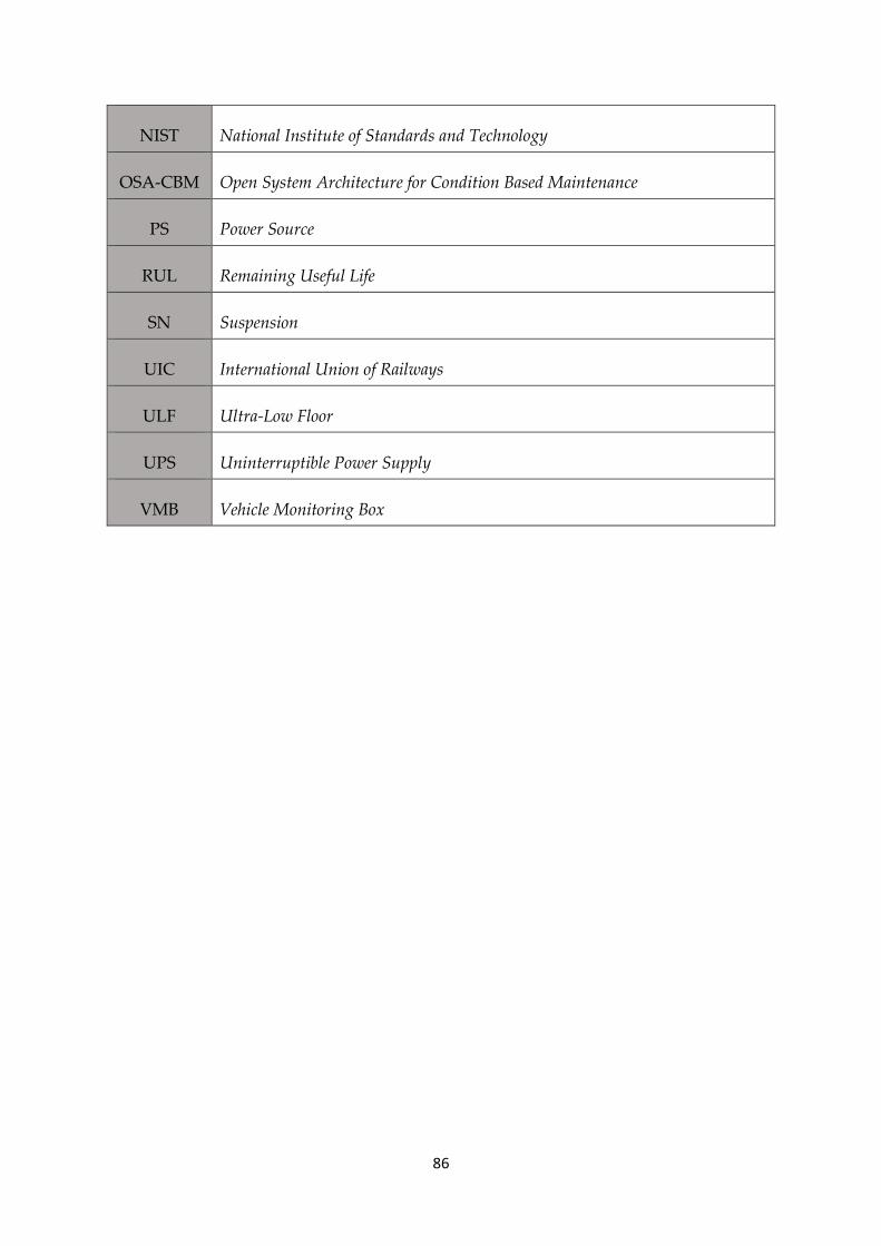
86
NIST National Institute of Standards and Technology
OSA-CBM Open System Architecture for Condition Based Maintenance
PS Power Source
RUL Remaining Useful Life
SN Suspension
UIC International Union of Railways
ULF Ultra-Low Floor
UPS Uninterruptible Power Supply
VMB Vehicle Monitoring Box