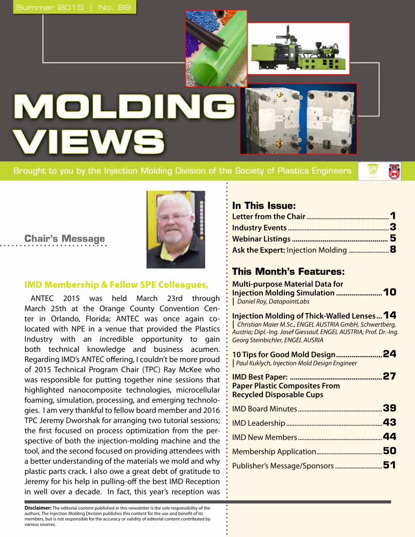
IMD Membership & Fellow SPE...
51
Disclaimer: The editorial content published in this newsletter is the sole responsibility of the authors. The Injection Molding Division publishes this content for the use and benefit of its members, but is not responsible for the accuracy or validity of editorial content contributed by various sources. Chair’s Message IMD Membership & Fellow SPE Colleagues, ANTEC 2015 was held March 23rd through March 25th at the Orange County Convention Cen- ter in Orlando, Florida; ANTEC was once again co- located with NPE in a venue that provided the Plastics Industry with an incredible opportunity to gain both technical knowledge and business acumen. Regarding IMD’s ANTEC offering, I couldn’t be more proud of 2015 Technical Program Chair (TPC) Ray McKee who was responsible for putting together nine sessions that highlighted nanocomposite technologies, microcellular foaming, simulation, processing, and emerging technolo- gies. I am very thankful to fellow board member and 2016 TPC Jeremy Dworshak for arranging two tutorial sessions; the first focused on process optimization from the per- spective of both the injection-molding machine and the tool, and the second focused on providing attendees with a better understanding of the materials we mold and why plastic parts crack. I also owe a great debt of gratitude to Jeremy for his help in pulling-off the best IMD Reception in well over a decade. In fact, this year’s reception was In This Issue: Letter from the Chair ................................................. 1 Industry Events ............................................................ 3 Webinar Listings .................................................. 5 Ask the Expert: Injection Molding ........................ 8 This Month’s Features: Multi-purpose Material Data for Injection Molding Simulation ........................ 10 | Daniel Roy, DatapointLabs Injection Molding of Thick-Walled Lenses ... 14 | Christian Maier M.Sc., ENGEL AUSTRIA GmbH, Schwertberg, Austria; Dipl.-Ing. Josef Giessauf, ENGEL AUSTRIA; Prof. Dr.-Ing. Georg Steinbichler, ENGEL AUSRIA 10 Tips for Good Mold Design ........................ 24 | Paul Kuklych, Injection Mold Design Engineer IMD Best Paper: ................................................ 27 Paper Plastic Composites From Recycled Disposable Cups IMD Board Minutes .................................................. 39 IMD Leadership ......................................................... 43 IMD New Members .................................................. 44 Membership Application....................................... 50 Publisher’s Message/Sponsors ............................ 51
Transcript of IMD Membership & Fellow SPE...
Disclaimer: The editorial content published in this newsletter is the sole responsibility of the authors. The Injection Molding Division publishes this content for the use and benefit of its members, but is not responsible for the accuracy or validity of editorial content contributed by various sources.
Chair’s Message
IMD Membership & Fellow SPE Colleagues,ANTEC 2015 was held March 23rd through
March 25th at the Orange County Convention Cen-ter in Orlando, Florida; ANTEC was once again co-located with NPE in a venue that provided the Plastics Industry with an incredible opportunity to gain both technical knowledge and business acumen. Regarding IMD’s ANTEC offering, I couldn’t be more proud of 2015 Technical Program Chair (TPC) Ray McKee who was responsible for putting together nine sessions that highlighted nanocomposite technologies, microcellular foaming, simulation, processing, and emerging technolo-gies. I am very thankful to fellow board member and 2016 TPC Jeremy Dworshak for arranging two tutorial sessions; the first focused on process optimization from the per-spective of both the injection-molding machine and the tool, and the second focused on providing attendees with a better understanding of the materials we mold and why plastic parts crack. I also owe a great debt of gratitude to Jeremy for his help in pulling-off the best IMD Reception in well over a decade. In fact, this year’s reception was
In This Issue:Letter from the Chair .................................................1Industry Events ............................................................3Webinar Listings .................................................. 5Ask the Expert: Injection Molding ........................8
This Month’s Features:Multi-purpose Material Data for Injection Molding Simulation ........................10| Daniel Roy, DatapointLabs
Injection Molding of Thick-Walled Lenses ...14| Christian Maier M.Sc., ENGEL AUSTRIA GmbH, Schwertberg, Austria; Dipl.-Ing. Josef Giessauf, ENGEL AUSTRIA; Prof. Dr.-Ing. Georg Steinbichler, ENGEL AUSRIA
10 Tips for Good Mold Design ........................24| Paul Kuklych, Injection Mold Design Engineer
IMD Best Paper: ................................................27Paper Plastic Composites From Recycled Disposable Cups
IMD Board Minutes ..................................................39IMD Leadership .........................................................43IMD New Members ..................................................44Membership Application .......................................50Publisher’s Message/Sponsors ............................51

Chair’s Message ContinuedPage 2 Summer 2015
reminiscent of that from ANTECs of old. High quality presentations, large injection-molding machines, and a great networking reception — what more could a PLASTICS GEEK ask for.
IMD members, I really hope you were able to attend ANTEC 2015, but recent trends tell me that if you are from “industry” (as opposed to academia), the chances are very good that you did not participate in ANTEC. Quite frankly, I am very concerned about the indifference shown by my industry colleagues to our annual technical conference — are you opting out for a more specialized TopCon or Minitec? I’d like to know. I certainly hope that our maturing industry hasn’t become complacent; but, if that is the case, then I call for change and it is time to get involved. A good place to start would be to at-tend the next IMD business meeting or any SPE conference of interest — IMD Board Members are looking at the possibility of co-hosting a Minitec with our colleagues in the Mold Making & Mold Design Division later in the 2015 calendar year. You could also consider becoming an IMD Sponsor. Sponsorship monies help your Board fund: 1) the ANTEC IMD Reception, 2) community outreach programs, 3) technical programming such as TopCons, Minitecs, and webinars, and 4) senior capstone projects at universi-ties such as Penn State and Western Michigan. Please contact me directly to discuss any one of several levels of sponsorship that are available as well as other opportunities where you can make a difference; you can find my email address on the IMD web site – http://injectionmolding.org/.
Best regards to all,David A. OkonskiIMD Chair & Staff Engineer, GM Global R&D Center

Industry Events Calendar
SPE Injection Molding Division www.4spe.org
Page 3 Summer 2015
Click the show links for more information on these events!
July 2015July 28 Novel Trends in Rheology VIThe international conference ‘Novel trends in rheology VI’, July 28 – 29, 2015, is organized by the Polymer Centre, Faculty of Technology, Tomas Bata University in Zlín in cooperation with the Applied rheology division, the Society of Plastics Engineers (SPE) and the Czech Group of Rheology. The meeting will capture recent development in areas of experimental and theoretical rheology, non-Newtonian fluid mechanics, applied rheology for advanced polymer processing with specific attention to polymeric nanofibers production.www.4spe.org
August 2015August 31- September 3SPE Thermoforming Conference® 2015Cobb Galleria Centre Renaissance Atlanta Waverly HotelThe SPE Thermoforming Division invites you to attend its 24th Annual Conference created exclusively by and for the Thermoforming Industry. The Conference will be held at the Cobb Galleria Centre and the Renaissance Atlanta Waverly Hotel. Network with clients, vendors and industry leaders in one convenient location! Our exhibit hall will provide you with opportunities to meet with equipment, material, tooling and service providers. The SPE Thermoforming Conference® is the most convenient and cost-effective way to learn about the Industry.www.4spe.org
September 2015September 8-11 Foams 2015 and TutorialFOAMS® 2015 conference is planned in Kyoto, Japan, to address the advances in synthesis, characterization and properties of polymer foams by leading foam researchers in industry and academia.www.4spe.org
September 15-17 westec 2015WESTEC, the West Coast’s premiere manufacturing event, gives you access to hundreds of industry experts and allows you to evaluate and compare cutting-edge manufacturing equipment, advanced technologies, new products and applications.http://www.westeconline.com
September 28-October 1 Canadian Manufacturing Technology ShowMeet 8,000+ manufacturing professionals who attend CMTS to source the latest in Machine Tools, Tooling, Metalworking, Forming, Fabricating, 3D Printing, Automation, and Designhttp://cmts.ca
October 2015October 20-21 Additive Manufacturing ConferenceThe focus of the Additive Manufacturing Conference is on industrial applications of additive technologies for making functional components and end-use production parts. It will cover the processes, applications and materials to give you practical knowledge on how to implement AM in your facility.http://www.additiveconference.com/events/additive-manufacturing-2015/event-summary-fdd05bae8ee349cb8c60c9bd08e03500.aspx
October 29 Mold Flow Simulation- What Information Do You Get? Erik Foltz, The Madison Group
November 2015November 4IMD Webinar SeriesGate/Runner Design Matthew Jaworski, Autodesk
November 18 IMD Webinar Series Injection Molding Part Design Fundamentals Mark Matsco, Bayer Material Science

B R E A K & A D V E R T I S I N G
G O L D & E X H I B I T O R
E X H I B I T O R
2015 SPE AUTOMOTIVE ENGINEERED POLYOLEFINS CONFERENCE SPONSORS
P L A T I N U M
Exhibit & Sponsorship Opportunities
Now in its 17th year, the show is the world’s leading automotive engineered polyolefins forum featuring 60+ technical presentations, keynote speakers, networking receptions, & exhibits that highlight advances in polyolefin materials, processes, and applications technologies as well as a growing range of thermoplastic elastomers (TPEs) and thermoplastic vulcanizates (TPVs). This year’s show will be held Oct. 4-7, 2015at the Troy-Marriott (Troy, Michigan) in the suburbs of Detroit.
Showcase your products and services at the world’s leading automotive engineered polyolefins forum. Many sponsorship packages are available. Companies interested in showcasing their productsand/or services at the SPE Auto TPO Conference should contact [email protected].
www.spedetroit.org or www.speautomotive.com/tpoPH: +1.248.244.8993, Ext. 3Email: [email protected]
SPE Detroit Section 1800 Crooks Road, Suite A
Troy, MI 48084, USA
Attend the World’s Leading Automotive
Engineered Polyolefins Forum
Injection Molding Design FundamentalsNovember 18: Presented by Mark Matsco, Bayer Material Science
In order to meet the demanding challenges of performance, appearance, and cost economics of a plastic part application, the part design must accommodate the unique properties of plastic materials and take full advantage of the design possibilities af-forded by the molding process. The design must be tailored to meet the structural and dimensional needs of the application, and where possible, should incorporate integration features that ease assembly and handling. At the same time, the part design must also work within the constraints the injection molding process, to meet quality and cost targets.
This webinar is intended for anyone involved in the design and manufacture of molded thermoplastic parts. The focus will be on the fundamentals of injection molded thermoplastic part design, providing specific recommendations for materials such as poly-carbonate and polycarbonate blends. Key topics include the design process, structural design, design for assembly, surface quality considerations and design for moldability. Several advanced topics such as design for thin-wall, gas-assist and other advanced processes will also be discussed.
In 1982 Mark M. Matsco began his career as a Structural Engineer for Bechtel Power Corporation. He became a Research Assistant at Michigan Technological University in 1984, and in 1985 he accepted a position as Research Engineer with Dow Chemical. He joined Bayer Corporation in 1987 as a Senior Design Engineer. In 1989, he started a delegate assignment to Bayer AG in Leverkusen, Germany where he worked in processing, CAE, design, testing and marketing. He returned to Pittsburgh in 1993 as Design Engineering Supervisor. Two years later he was promoted to Manager of Innovative Technologies, a position he held until his Technology Manager appoint-ment with Exatec LLC, a joint venture company formed by Bayer AG and GE Plastics. In 2001 Matsco returned to Bayer Corporation in Pittsburgh in the position of Processing Technology Manager. In 2002 Matsco was appointed Director of Application Development. In this role he leads the Application Development team in providing plastic part/mold design, engineering, cost estimations, computer-
aided analysis, tooling expertise, optimization, concept solutions, advanced processing, part testing and on-site technical service.Matsco received both his bachelor’s degree in structural engineering and master’s degree in mechanical engineering from Michigan Technological
University. A member of the Society of Plastics Engineers (SPE), Society of Automotive Engineers (SAE) and author of numerous technical papers, Matsco is a frequent speaker at plastics industry events. Matsco currently holds seven design and process patents.
Join our Fall webinar series only at SPE.
Everything You Wanted to Know About Plastics Simulation but Were Afraid To AskOctober 29: Presented by Erik Foltz, The Madison Group
Even though injection molding simulation has been around for almost 40 years, there are still many questions about its capabili-ties and accuracy. This presentation will start with an introduction to injection molding simulation briefly summarizing its history and milestones. A review of current capabilities and how it can be used to reduce, solve and optimize common issues will be pre-sented. Find out how companies, perhaps even your competitors, are using simulation workflows to produce better plastics parts from upfront design feedback to optimization of manufacturing via design of experiments.
Erik Foltz is a Senior Managing Engineer at The Madison Group, an independent plastics consulting firm. As a Certified Professional Moldflow® Consultant at The Madison Group, he helps industrial clients verify their plastic part designs and optimize and troubleshoot their injection molding process through the use of computer simulation. Mr. Foltz received his M.S. from the Polymer Engineering Cen-ter at the University of Wisconsin – Madison. His specialties include plastic part design verification, process optimization and trouble-shooting for injection and compression molding, and failure analysis of plastic products. Mr. Foltz is an active member of the Society of Plastics Engineers, where he serves as a board member of the Injection Molding Division (IMD). He is currently the IMD Technical Program Chair for ANTEC® 2012
Importance of Runner and Gate Design for Injection Molded Plastic PartsNovember 4: Presented by Matthew Jaworski, Autodesk
Often seen as throw away material the design of the runner and gate scheme is often overlooked during the injection mold de-sign process. However, the design of the runner and gate is critical to the manufacturing of quality parts. Not only do these features allow the melt to enter the molding cavity, but they also prepare the melt during injection. An improperly placed or sized runner or gate can lead to cosmetic issues, extreme processing conditions, and excessive cycle times. This presentation will highlight the key design features and guidelines that should be considered during design, and it influences the manufacturability of the part.
Matt Jaworski is a Technical Specialist for Autodesk’s Manufacturing Simulation Team. He has over 17 years’ experience in the injec-tion molding CAE simulation field working for such companies as Hewlett Packard, Rubbermaid and Moldflow/Autodesk. He has dual BS degrees in Mechanical and Plastics Engineering Technology from Penn State, a MS in Plastics Engineering from UMass Lowell and is cur-rently finishing his Ph. D. at UMass Lowell in Plastics Engineering. He is a member of the Society of Plastics Engineers and the American Society for Engineering Education. Matt is also active in education and has taught at the University of Massachusetts Lowell and Penn State Erie, The Behrend College as an adjunct professor.

SPE Injection Molding Division www.4spe.org
FeaturePage 6 Summer 2015
Webinars
Getting Real about Manufacturing Education to Fill the Skills Gap: Key Elements of a Local Teaching StrategyThursday, September 03, 2015 2:00 PM - 3:00 PM EST
Fundamentals of Twin-Screw Extrusion Polymer Melting: Common pitfalls and how to avoid themAugust 06 ,2015
As-manufactured Structural Simulation of Short Fiber Reinforced Plastic Parts
High Density Compounds - Processing Do’s and Don’ts
Advancements in Lightweighting with Polypropylene Compounds

At Plastic Engineering & Technical Services, we are.We define performance. For nearly 30 years, we’ve helped our
customers to produce more efficiently, with lower cycle times
and lower per unit costs.
Our new compact stainless steel, modular unitized system
features flexible heaters that can be utilized on multiple designs,
so you don’t have to stock custom bent heaters. Our new drop
heaters provide more uniform heating and feature smaller
pockets and no clamps. They have in-line flow restrictors
for better process repeatability, and no over-pressurizing the
cylinders. It all adds up to a reduced sized hot runner system,
shorter heating times and better tool performance.
We deliver value. We complement our hardware with
leading-edge analytical tools, including Moldflow® and
MOLDEX3D software. We’ll work with you on design issues
and optional gating solutions before the mold or hot runner
manifold system is ever built. Use us for the mold flow analysis
and the manifold build, and we’ll do whatever it takes to make
your hot runner/manifold system work to your complete
satisfaction.
We’re committed to your success. Find out more.
Call us today at 248.373.0800 or visit us at www.petsinc.net.
Who’S BRINGING NEW LEVELS oF PERFoRmANCE To ComPACT hoT RuNNER/mANIFoLd SySTEmS?

SPE Injection Molding Division www.4spe.org
FeaturePage 8 Summer 2015
Ask the Experts: Bob Dealey
I received a call from Mr. Barnhart inquiring about an injection molding source. He provided this information:
1. He has a business of designing and supplying Point of Purchase display items to a number of clients.
2. The display shelves or racks are injection molded, decorated by hot stamping (or other decorating techniques). Many products include electronics where a light blinks or a recorded message is played when a consumer approaches.
3. He wants to buy the complete assembly. 4. What he is looking for is a molder in Mexico that can handle the entire proj-
ect from obtaining the tooling to packing and shipping the completed prod-uct to a distribution center in the Chicago area.
5. Currently, the work is being done in China and has been for 10 plus years, but the story is always the same; the project runs behind, he is always on a plane traveling to resolve issues and by then the six to eight weeks shipping by boat either delays the roll out date or the client threatens to cancel the project.
Mr. Barnhart is asking for recommendations of companies who do this type of work and/or perhaps makes toys where similar operations are incorporated in their manufacturing facilities.
I’m unable to provide him with a company in Mexico that I know of that fits his requirements. However, it raised the question in my mind if there could be a company in the USA who has the capabilities and interest in talking with Mr. Barnhart regarding this opportunity. If so, please let me know and I will arrange an introduction. I can be reached at [email protected] or + 1 (414) 690-5700.
Bob Dealey [email protected]
Injection Molding Source Needed
Bob Dealey, owner and president of Dealey’s Mold Engineering, Inc. answers your questions about injection molding.
Bob has over 30 years of experience in plastics injection-molding design,tooling, and processing.
You can reach Bob by e-mailing [email protected]

Page 9 Summer 2015
Wednesday, March 25th, 2015 was the date for the Injection Molding Division (IMD) reception at
ANTEC in Orlando, FL.
AutoDesk was the primary sponsor for the event and delighted the crowd (150-200 people) with
numerous prize giveaways throughout the evening!
Individuals were given awards and recognized at the reception: ANTEC Best Paper, Engineer of
the Year, Past Chair, Technical Program Chair (TPC), and special recognition for two Plastics Hall of
Fame inductees (John Beaumont and Maureen Steinwall).
Thank you to all the sponsors of the event:
Gold: AutoDesk,
Silver: Alcoa, Beaumont, DRS, IQMS, Master Precision, Moldex3D, and SPE Detroit Section,
Bronze: Steinwall, Inc., and Wisconsin Engraving.
Looking forward to 2016: IMD plans to have another successful reception at ANTEC in
Indianapolis! We hope to see you there!

Page 10 Summer 2015
SPE Injection Molding Division www.4spe.org
Feature: Multi-purpose Material Data for Injection Molding Simulation
Data requirements for injection molding simulation vary among different CAE platforms. These distinctions can plague those who have to support more than one type of CAE software in the course of their work. Material suppliers and product development groups, particularly those with a global presence, are coming to the realization that it is best to be prepared for this. Here is an increasingly common scenario that we see in our material testing laboratory:
A customer based in the US approaches us with a request for full molding characterization of a semi-crystalline material for use in a Moldflow simulation. We provide the full complement of testing and data processing to meet that requirement. The customer walks away happy in the knowledge that they now have this digital material data and the corresponding input (UDB) file stored away in their company’s Matereality database, perfectly prepared for use whenever they need it.
Then we get that inevitable call. “Your lab tested a material for us some time ago for Moldflow characterization, and now my European counterpart needs that data fit for use in Sigmasoft.” The unfortunate news here is that additional testing will be required. Why can’t we just refit that same properties data set for use in Sigmasoft and be done with it? This is because each brand of software requires similar, but not identical material property inputs, and they differ in subtle and potentially costly ways.
Continuing with our example of a semi-crystalline material, let’s assume we are interested in an uncorrected, isotropic shrinkage characterization. The requirements are:
Moldflow SigmasoftCapillary rheology measurements at three temperatures Bagley-corrected capillary rheology at three
temperatures
Specific heat Specific heat
Thermal conductivity scan Thermal conductivity scan
Isothermal PVT test Isobaric PVT test
Thermal expansion coefficient by TMA Thermal expansion coefficient by TMA
Poisson’s ratio and tensile modulus Temperature-dependent modulus and Poisson’s ratio
Multi-purpose Material Data for Injection Molding Simulation
By Daniel Roy , DatapointLabs.
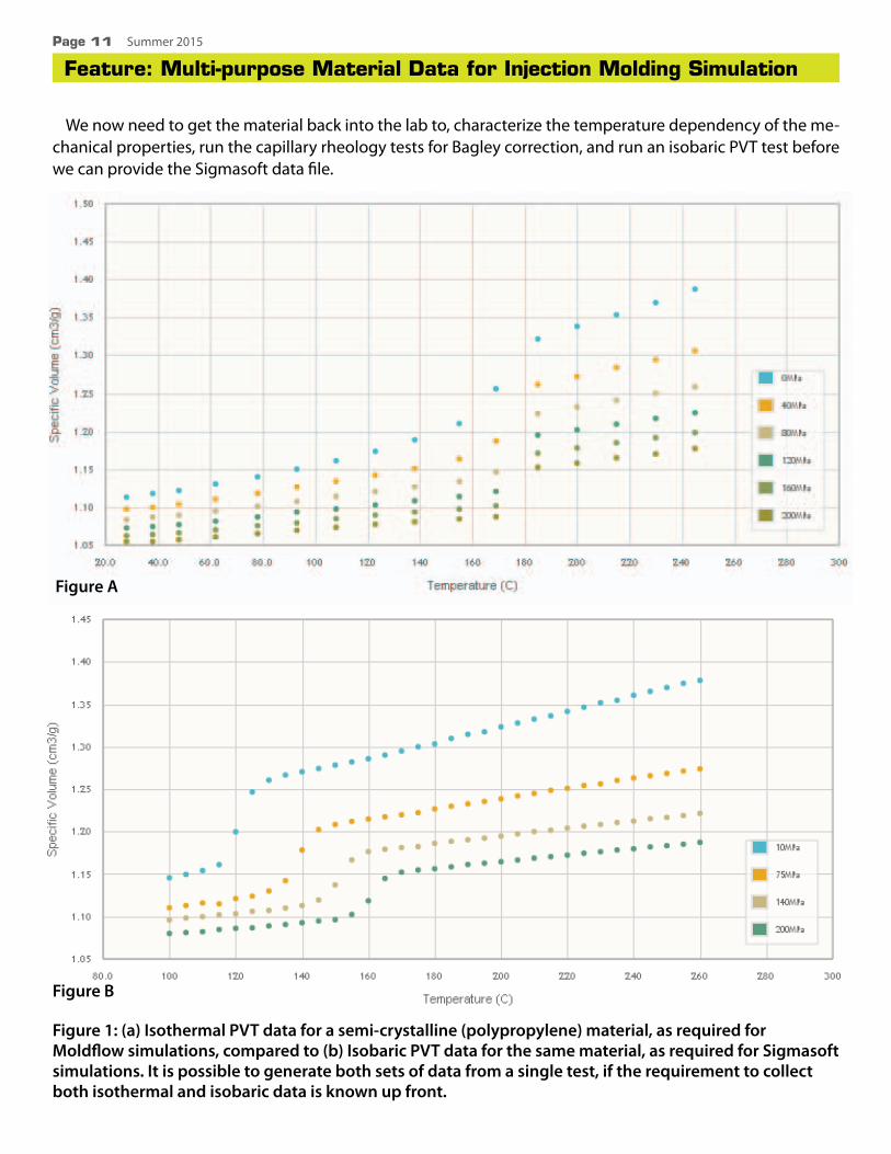
Figure 1: (a) Isothermal PVT data for a semi-crystalline (polypropylene) material, as required for Moldflow simulations, compared to (b) Isobaric PVT data for the same material, as required for Sigmasoft simulations. It is possible to generate both sets of data from a single test, if the requirement to collect both isothermal and isobaric data is known up front.
Feature: Multi-purpose Material Data for Injection Molding SimulationPage 11 Summer 2015
We now need to get the material back into the lab to, characterize the temperature dependency of the me-chanical properties, run the capillary rheology tests for Bagley correction, and run an isobaric PVT test before we can provide the Sigmasoft data file.
Figure A
Figure B

SPE Injection Molding Division www.4spe.org
Feature: Multi-purpose Material Data for Injection Molding SimulationPage 12 Summer 2015
All this assumes, of course, that there is still sufficient material stored somewhere to accomplish the second round of tests, and that it hasn’t been sitting around for years in adverse environmental conditions.
Material suppliers have another potential pitfall to deal with. Characterizing a material for only one CAE platform will likely mean coming back to the lab at some point to fill in missing data required by other CAE platforms. If too much time has elapsed since the first round of testing, there may be a need to produce more material. Subtle changes in formulation between lots could lead to measurable changes in properties, which would mean the new material must now be completely retested.
There is a solution to this obvious waste of money and time: test for multiple CAE platforms right from the start. Multi-CAE TestPaks® were designed specifically to generate the full range of data required by multiple CAE platforms that address similar simulation goals but require different material properties data as input.
The previous example of differing requirements for Moldflow and Sigmasoft packages could have been pre-vented by ordering the appropriate Multi-CAE Molding TestPak, in this case a post-filling + isotropic shrinkage and warpage characterization. All of the tests listed above are incorporated, including temperature depen-dency of mechanical properties and both isothermal and isobaric PVT tests. The hidden benefit is that the isobaric and isothermal PVT tests can be performed in a single run, saving expensive lab time. Plus, customers who support various CAE platforms in their work can have the peace of mind that comes with knowing their data is now fully ready for use in Moldflow, Sigmasoft, Moldex3D and Simpoe-Mold simulations.
About the Author:Daniel Roy is a Mechanical Engineer with DatapointLabs. DatapointLabs and its affiliate, Matereality, USA, form a comprehensive resource for strengthening the materials knowledge core of manufacturing enterprises. For 20 years, DatapointLabs’ Technical Center for Materials has provided accurate material testing, TestPaks® material parameter conversion, and CAETestBench™
model validation services for CAE, allowing companies to populate their databases with high-quality, application-ready data for design and new product development. Matereality’s Software for Materials gives companies the means to build databases to store properties, CAE material files, and related information on any material. The built-in suite of web-based software helps engineers visualize and understand material data, create CAE models, and manage materials information.TestPaks is a registered trademark and CAETestBench is a trademark of DatapointLabs, LLC. Moldflow, Sigmasoft, Moldex3D and Simpoe-Mold are registered trademarks or trade names of their respective owners, who are CAE Software Partners of DatapointLabs.
www.datapointlabs.com Tel: +1-607-266-0405 | Fax: +1-607-266-0168

Do you know an IMD member who has made outstanding contributions to the industry or SPE?
If you know of an IMD member who deserves the special recognition of Fellow or Honored Service Member (HSM), please send an e-mail to Dr. and Professor Lih-Sheng (Tom) Turng ([email protected]) with a brief description of their accomplishments by July 31, 2015.
According to SPE Bylaws, “To be elected an Honored Service Member, a candidate shall have demonstrated long-term, outstanding service to, and support of, the Society and its objectives; shall be sponsored, in writing, by the Board of Directors of at least one Section or Division.” On the other hand, fellow members are honored for their outstanding contributions in the field of plastics engineering, science or technology, or in the management of such activities.
Deadline for the submission of a completed application is generally around the end of September. Information about the Fellow and HSM member recognitions and nomination can be found at:
http://www.4spe.org/Leadership/Content.aspx?ItemNumber=5986&navItemNumber=680http://www.4spe.org/Leadership/Content.aspx?ItemNumber=5983

Christian Maier M.Sc., project head in the process technology development department, ENGEL AUSTRIA GmbH, Schwertberg, Austria; [email protected]. Josef Giessauf, head in the process technology development department, ENGEL AUSTRIA; [email protected]. Dr.-Ing. Georg Steinbichler, Senior Vice President of Development Technologies, ENGEL AUSRIA, and director of the Institute of Polymer-Injection Molding Technology and Process Automation at Johannes Kepler University, Linz, Austria; [email protected]
Feature: Injection Molding of Thick-Walled LensesPage 14 Summer 2015
Injection molding is again demonstrating its versatility in the production of challenging optical plastic parts such as LED lenses for automotive headlights, with tolerances in the micron range. A new development in multilayer in-jection molding allows a further increase in productivity for the production of thick-walled lenses.
The markets for plastic optical parts differ significantly from region to region. While imaging optical parts for mobile appli-ances is predominate in Asia, in Europe the main focus is on the production of thicker lenses for LED lights. Since the cooling time during injection molding increases with the square of the wall thickness, the biggest challenge is to develop economic processes. With a typical thickness of 30 mm for automotive headlamps cycle times of at least 20 minutes are to be expected with standard injection molding processes 1.
Injection Molding of Thick-Walled Lenses Efficient Production of Thick-Walled Parts
Figure 1: Possible layer sequences for the example of a thick-walled three layer lens. Left: Preform 1 one-side overmolded with layers 2 and 3 sequentially; center: Preform 1 simultaneously overmolded on both sides with layers 2 and 2’ (sandwich variant); right: Preforms 1 and 1’ connected by injection of a second layer 2. Figure courtesy of ENGEL.
Above: The layers are manufactured by three-layer sandwich molding on an ENGEL duo 600 WP pico combi injection molding machine.Photo courtesy of Automotive Lighting Reutlingen

SPE Injection Molding Division www.4spe.org
Feature: Injection Molding of Thick-Walled Lenses ContinuedPage 15 Summer 2015
One possibility for cycle time reduction is multilayer technology, in which the thick-walled parts are built up from multiple successive layers. The multilayer structure can be generated by overmolding a first layer on either one or both sides, or by subsequently bonding together two previously independent layers by means of an interlayer (see Figure 1).
In general, the individual layers are all produced on the same injection molding machine. The use of separate injection units for the three layers is a first step towards short cycle times. This ensures that the process steps of injection, holding pressure and metering take place simultaneously and independently of one another.
What are the Benefits of Multilayer Technology?Approximation formulas for cooling time and productivity can be derived from theoretical considerations
(see box) and the results illustrated dependent on the number of layers (see Figure 2). The literature 1–3, however, shows that this rule of thumb provides results that are too optimistic for estimating the cooling time saving.
Multilayer molding, however, offers the possibility of maintaining the mold regions for those surfaces that subsequently have to be overmolded at a lower temperature, since, in an ideal case, the surface quality of the internal layers does not affect the quality of the lens that is produced. If this potential is used for the manufacture of the preform, the estimated cooling time reduction agrees well with simulated and practical results. For optimizing the layer thickness distribution, it is advisable to carry out simulations.
Figure 2: Cooling time per station in the mold, depending on the number of layers as per equation 4, and productivity as per equations 6 and 7 (see box). The respective single-layer part serves as reference (100 %) for comparing the illustrated results for overmolding on one side and on both side. Figure courtesy of ENGEL.

SPE Injection Molding Division www.4spe.org
Feature: Injection Molding of Thick-Walled Lenses ContinuedPage 16 Summer 2015
From Figure 2, the following statements can be derived:• For the cooling time per cavity, it is unimportant whether overmolding is performed on one or both sides.
In both cases the cooling time is reduced to the same degree as the number of layers increases.
• Overmolding on one side requires a larger number of cavities, and therefore more space in the mold, compared to overmolding on both sides.
• Productivity is a suitable key indicator for an economic comparison, because it includes the assumption of equal numbers of cavities.
• It is only with a large number of layers that overmolding on one side improves productivity to a significant extent. However, the productivity actually obtainable is affected by the times for mold opening, mold closing, mold transfer/rotation and injection.
• For overmolding a preform on both sides, on the other hand, the productivity increases significantly starting with a three layer structure.
The sandwich option, consequently, has an advantage above overmolding on one side. This alternative also improves the contour accuracy, since sink marks in the preform due to shrinkage can be compensated by overmolding. Shrinkage of the thinner outer layers is thus responsible for the contour accuracy. This effect is also present for overmolding on one side, but of course only on one side. The quality of the other surface must therefore meet requirements immediately after molding, since it does not contain a corrective top layer.
Where there is light, there is also shadow: despite all the advantages of the sandwich alternative, it must not be overlooked that it requires a more complex mold technology. Retaining the preform in the cavity and transportation from one cavity to another is challenging, while a rotary table is sufficient for one-sided overmolding. The simultaneous filling of the outer layers should be well balanced — pressure differences between the top and bottom layers can cause the preform to fracture.
Both methods can offer further benefits. Cold-runner sprues or thin-walled exterior regions limit the possible maximum holding pressure time. With very thick-walled parts, the sink marks can thus only be counteracted by increasing the holding pressure. This in turn requires machines with relatively high clamping forces. Extreme wall-thickness ratios can, in some cases, only be achieved through multilayer molding. The result is a gain in design freedom.
With the cycle time, the residence time of the material in the barrel and hot runner also decreases. That has the benefit of reduced yellowing and therefore greater transmission. The maximum residence times recommended by the material manufacturers can be maintained. The Title figure shows a series application of the three-layer sandwich process, production of LED headlamps at Automotive Lighting Reutlingen GmbH in Germany.
Shorter Cycle Times thanks to Longer Cooling TimesIt has been explained above and it can be seen in the box how multilayer molding can increase the
profitability of the production of thick-walled parts. It takes advantage of the fact that several thin layers will cool more rapidly than one thick layer. This can increase productivity by approximately a factor of two. However, the resulting cooling times of several minutes are still comparatively long for injection molding.
Considerations about the layer distribution generally assumed that, with a three-layer sandwich struc-ture, the preform and the top layers must be cooled to below the glass transition temperature at the end of the cooling time. However, tests have shown that the preform can be removed much earlier. It must only be ensured that its solidified outer layers are sufficiently strong to withstand the internal pressure and pre-

SPE Injection Molding Division www.4spe.org
Feature: Injection Molding of Thick-Walled Lenses ContinuedPage 17 Summer 2015
vent deformation during demolding. If the preform is immediately overmolded in the next station, no cycle time reduction would be gained, on the contrary: the still-hot inner regions of the preform would be further distanced from the mold wall and the cooling time would be extended.
A new process therefore includes a cooling stage outside the mold between the injection shots. Cooling in air does take longer than in the mold, but does not influence the cycle time. Depending on the duration of the external cooling, the preform can have a lower average temperature during overmolding than a preform in conventional sandwich technology. As a result, the preform absorbs more heat from the top layers and thereby reduces the cooling time. This effect can be further increased by making the preform thicker and the top layers thinner.
Process Sequence with External CoolingThe new process sequence is as follows: A preform for some cycles externally cooled to a predefined
temperature is inserted into the mold again and overmolded. A new preform is then produced simultaneously or sequentially depending on the number of injection units. After the opening of the mold, a finished part and a preform are removed and a preform that has previously been intermediately cooled is inserted again. The removed preform is deposited at a cooling station (see Figure 3).
Figure 3: Time sequence of the process steps for conventional three-layer sandwich molding (top) and the variant with external intermediate cooling (bottom). The diagram shows schematically how the different temperature at demolding of the preform (Tg: glass transition temperature) and the different layer distribu-tion significantly shorten the overall cooling time. Figure courtesy of ENGEL.

Feature: Injection Molding of Thick-Walled Lenses ContinuedPage 18 Summer 2015
To put a figure on the cycle time reduction gained by cooling outside the mold, Bayer MaterialScience AG, Leverkusen, Germany, performed thermal simulations for a 20 mm-thick cuboidal part of polycarbonate (PC) (see Figure 4). The specialists compared a one-layer process, a three-layer sandwich process and a three-layer sandwich process with external intermediate cooling. The layer thickness distribution was adapted to the process. In the three-layer sandwich process, the 4mm thick top layers required the same cooling time as the preform with 12 mm thickness. In a variant with external intermediate cooling, the preform was assumed to have a thickness of 12.8 mm, and the top layers of 3.6 mm. Figure 5 shows the maximum temperature within
Figure 4: For a process comparison, a cuboidal polycar-bonate part (40 × 38 × 20 mm) was used. Figure courtesy of Bayer MaterialScience.
Figure 5: Simulated maximum temperature within the part in dependence of time for a single-layer process (top), a three-layer sandwich process (center) and the new three-layer sandwich process with external inter-mediate cooling (melt temperature 280 °C, mold temperature outer layers and single-layer variant: 120 °C, mold temperature inner layers: 70 °C). The graphics also include the temperature distribution in the part inte-rior after 164 s. Figure courtesy of Bayer MaterialScience.

SPE Injection Molding Division www.4spe.org
Feature: Injection Molding of Thick-Walled Lenses ContinuedPage 19 Summer 2015
the part in dependence of time. Whereas with the one-layer alternative, the highest temperature is always found in the core of the part, the location of the maximum changes for the two multilayer processes.
The criterion for calculating the cooling time of the end part is: all regions of the part must be cooled to below the glass transition temperature of 150°C. In the alternative with external intermediate cooling, the preform is removed at a time when a 2.4 mm-thick, solidified outer layer has formed, but the core temperature is still 220 °C. With this new process the total cooling time in the mold can be cut in half. Since the number of required cavities is the same compared to the known sandwich process, the productivity increases by the same factor at which the cooling time decreases.
The rapid solidification rate of polycarbonate is beneficial for short cycle times. Simulations for polymethyl methacrylate (PMMA) with adjusted melt and mold temperatures generated a total cooling time that, at 314 s, was almost twice as long. Figure 6 compares the cycle times and productivity of the three processes for the processing of polycarbonate.
Figure 6: Simulated cooling time per mold station and the calculated productivity for different manufactur-ing processes (material: PC). The single-layer part is used as a reference (100 %) for comparison. Figure courtesy of ENGEL.
Contact: [email protected]

SPE Injection Molding Division www.4spe.org
Feature: Injection Molding of Thick-Walled Lenses ContinuedPage 20 Summer 2015
Record Cycle TimeTests and simulations demonstrate that, for the manufacture of thick-walled parts with external intermedi-
ate cooling, the cooling time in the mold can be reduced by 25 to 50 % compared to conventional multilayer molding — depending on the geometry of the part. At K2013, the injection molding manufacturer ENGEL – together with its project partners Bayer MaterialScience and the Krallmann Group –demonstrated the poten-tial of this process live for the first time. The production of an optical lens from PC (type: Makrolon LED 2245) in record time was demonstrated.
References1 Pillwein, G.: Maschinen- und Prozesstechnik zur Herstellung optischer Bauteile. IKV Seminar: Spritzgießen
hochwertiger optischer Komponenten, Aachen 20082 Zöllner, O.: Kunststoffoptiken im Mehrschichtspritzguss. Dissertation, University of Erlangen-Nürnberg
20123 Klinkenberg, C.: Clear benefits of multi-layer. Injection World, Edition October 2012
The AuthorsChristian Maier M.Sc., project head in the process technology development department, ENGEL AUSTRIA GmbH,
Schwertberg, Austria; [email protected]. Josef Giessauf, head in the process technology development department, ENGEL AUSTRIA;
[email protected]. Dr.-Ing. Georg Steinbichler, Senior Vice President of Development Technologies, ENGEL AUSRIA, and director
of the Institute of Polymer-Injection Molding Technology and Process Automation at Johannes Kepler University, Linz, Austria; [email protected]
Cycle Time and Productivity – Considerations on the Layer StructureWhat layer sequence is most appropriate, how many layers are necessary and what savings potential can be
expected? These questions can be answered with a few considerations that apply to one-sided and two-sided overmolding, but not to the bonding of two preforms (Figure 1). Since the heat removal from the connecting layers follows relatively complex laws, this alternative will not be considered.
First, two assumptions are made: Firstly, known mold concepts (index plate, rotary table, sliding table) are used. Ideally, a further preform is manufactured simultaneously with the overmolding of one preform. From this the requirement, known from multicomponent injection molding, follows that the cooling times of all layers must be the same.
Second, it should be noted that only the layer manufactured first is cooled on both sides (layer 1 in Figure 1). The following layers only have contact with the mold wall on one side, while the preform borders on the other side, which, for the sake of simplicity, is regarded as an ideal insulator. To obtain the same cooling time in all stations, the following layers, which are cooled on one side, should be only half as thick as the first layer, which is cooled on both sides.
SPE Injection Molding Division www.4spe.org
Feature: Injection Molding of Thick-Walled Lenses ContinuedPage 21 Summer 2015
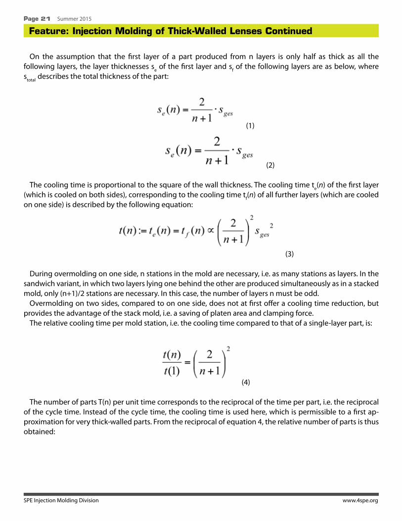
On the assumption that the first layer of a part produced from n layers is only half as thick as all the following layers, the layer thicknesses se of the first layer and sf of the following layers are as below, where stotal describes the total thickness of the part:
(1)
(2)
The cooling time is proportional to the square of the wall thickness. The cooling time te(n) of the first layer (which is cooled on both sides), corresponding to the cooling time tf(n) of all further layers (which are cooled on one side) is described by the following equation:
(3)
During overmolding on one side, n stations in the mold are necessary, i.e. as many stations as layers. In the sandwich variant, in which two layers lying one behind the other are produced simultaneously as in a stacked mold, only (n+1)/2 stations are necessary. In this case, the number of layers n must be odd.
Overmolding on two sides, compared to on one side, does not at first offer a cooling time reduction, but provides the advantage of the stack mold, i.e. a saving of platen area and clamping force.
The relative cooling time per mold station, i.e. the cooling time compared to that of a single-layer part, is:
(4)
The number of parts T(n) per unit time corresponds to the reciprocal of the time per part, i.e. the reciprocal of the cycle time. Instead of the cycle time, the cooling time is used here, which is permissible to a first ap-proximation for very thick-walled parts. From the reciprocal of equation 4, the relative number of parts is thus obtained:

SPE Injection Molding Division www.4spe.org
Feature: Injection Molding of Thick-Walled Lenses ContinuedPage 22 Summer 2015
(5)
However, the cooling time or number of parts are only conditionally suitable as values for an efficiency com-parison. These values do not take into account the fact that multilayer processes require a larger number of cavities. However, increased efficiency can be expected from larger numbers of cavities anyway. If with single-layer processes, for example, twice the number of cavities is available, the number of parts per unit time would also be twice as high.
The productivity is therefore used for the further assessment. It is defined as the ratio between the produced parts and the production factors necessary for this, in this case the cavities. To obtain the relative productiv-ity of multilayer molding compared to the single-layer method, equation 5 only needs to be divided by the number of cavities — i.e. by n in the case of overmolding on one side and by (n+1)/2 in the case of overmolding on both sides:
… for overmolding on one side (6)
… for overmolding on both sides (7)

Paul KuklychInjection Mold Design Engineer
SPE Injection Molding Division www.4spe.org
10 Tips For Good Mold DesignPage 24 Summer 2015
1. Thoroughly understand mold building and injection molding processing. Nothing beats hands on experience. Good injection mold design will reflect practical mold building tech-
niques and be capable of producing quality parts for the life of the mold (see Figure 1).
2. Understand the customers’ requirements.Use suitable materials for expected production volume. Design for quick setup and easy maintenance.Ensure mold tool correctly interfaces with specified moulding machines. Also make sure cooling system will
produce quality parts at the quoted cooling time.
3. Use as few components as possible.Fewer components means less cumulative error in the mold which translates into longer mold life and bet-
ter quality parts. Fewer components will make a stronger mold so add strength by changing size and shape of components not by adding more of them.
10 Tips For Good Mold Design
Figure 1

4. Design for surface grinding where possible.Surface grinding will produce the flattest and most parallel surfaces possible in mold building and it’s easy
to do. Having matching shut-off surfaces is one of the most important criteria for making good quality parts.
5. Design for strength.A mold needs strength to resist high clamp forces & injection pressures inside the mold cavity. Adequate
strength means correct plate thicknesses, proper interlocking method between fixed and moving sides, correct cavity size and use of suitable materials. A weak mold will produce reject parts since the processing window will be very narrow.
6. Gate location (single gate).Things to take into consideration when determining a gate location: Wall thickness - the first location to consider is the thickest wall in the part. If for some reason this is not
possible then go for the next thickest wall. Gates can be located in the thinnest wall of a part however, this is highly risky and could cause part quality problems especially if there are large differences in wall thickness across the part.
Flow path - the wrong flow path will produce weld lines which makes the part weaker and detracts from its appearance. Use flow simulation software to eliminate or minimize this issue in complicated 3D part shapes.
Flow length - the distance from the gate to the outer most edge of the part must be kept within limits. Plastic manufacturers have this data.
SPE Injection Molding Division www.4spe.org
10 Tips For Good Mold Design ContinuedPage 25 Summer 2015
update your specs...in a flash. unlock mold history
PROCOMPS.COM/CVe
End the searching by conveniently storing valuable mold information directly on the tool:
• Store part drawings, tool draw- ings, and setup sheets
• Access performance history and maintenance actions
Call 1-800-269-6653 to discuss how the CVe Monitor can connect you with your production tooling.

SPE Injection Molding Division www.4spe.org
10 Tips For Good Mold Design ContinuedPage 26 Summer 2015
7. Modify part design to enhance mold manufacture.Review part design to help make mold building easier. However, do not sacrifice mold strength in the
process.
8. Learn from mistakes.The only way to get the perfect design is to understand the faults in previous mold designs and avoid them
in the future. Get feedback from injection molder.
9. Experiment.Experiment with cooling design, ejection method, mold size and materials. The goal is to minimize mold
building costs while satisfying the needs of the injection molder.
10. Choose the right mold design engineerWhen hiring a mold designer, choose a specialist. This will minimize quality and productivity issues as the
designer understands how to avoid problems associated with the particular type of mold tooling. If you want to produce packaging products then hire a designer who specializes in packaging and not automotive since they both have their own unique traps.
About the AuthorPaul Kuklych has worked in various roles in the toolmaking and plastic injection mold-
ing industry. during the past 22 years. He started with machining and toolmaking then progressed to mold trial qualification. He now spends his time specializing in mold de-sign for thin wall packaging and doing troubleshooting work. Owner and author of www.improve-your-injection-molding.com, Paul can be reached at +61 3 95211911 or e-mail [email protected]
To read about his mold design services for packaging products go to: http://www.improve-your-injection-molding.com/mold-design-services.html
Improve Your Injection Molding Ltd604 St Kilda RoadMelbourne 3004, Australia.Office Phone +61 3 95211911

SPE Injection Molding Division www.4spe.org
IMD Best PaperPage 27 Summer 2015
Paper Plastic Composites From Recycled Disposable Cups
Jonathan Mitchell1, 2 3, Luc Vandeperre2, Rob Dvorak3, Ed Kosior3, Karnik Tarverdi4, Christopher Cheeseman1
1Department of Civil and Environmental Engineering, 2Department of Materials, Imperial CollegeLondon, London SW7 2AZ, UK3Nextek Ltd, 107-111 Fleet Street London EC4A 2AB4Wolfson Centre for Materials Processing, Brunel University, London, UB8 3PH
The majority of disposable cups are made from paper plastic laminates (PPL) which consist of high quality cellulose fibre with a thin in-ternal polyethylene coating. There are limited recycling options for PPLs which has contrib-uted to disposable cups becoming a high profile, problematic waste. In this work disposable cups have been shredded to form PPL flakes and these have been used to reinforce polypropylene to form novel paper plastic composites (PPCs). Samples were character-ized using mechanical analysis and thermogravimetric analysis (TGA). The work demonstrates that PPL dis-posable cups have potential to be beneficially reused as reinforcement in novel polypropylene composites.
IntroductionDisposable cups used for serving coffee, tea and oth-
er drinks at well-known retail outlets contain high quality virgin cellulose fibre board combined with a thin internal polyethylene (PE) coating. These types of paper plastic laminates (PPLs) are increasingly used in many disposable products and it is estimated that the leading coffee chains in the UK use approximately 500 million disposable cups each year. The strong bond between cellulose fibre board and the polyethylene coating make disposable cups and other types of PPLs difficult to recycle. With each cup typically weighing approximately 12.5g the total mass of waste disposable cups from leading coffee

SPE Injection Molding Division www.4spe.org
Paper Plastic Composites From Recycled Disposable Cups ContinuedPage 28 Summer 2015
chains alone in the UK is 6,250 tonnes, with the vast majority being disposed of to landfill or via combustion in energy from waste facilities. 1,2
Waste electrical and electronic equipment (WEEE) is rapidly increasing worldwide3. It is estimated that 8.3-9.1 million tonnes of WEEE are currently generated annually in the EU, which equates to approximately 17 kg per capita4. WEEE typically contains between 10 and 30 wt.% of engineering plastics with polypropylene (PP) as the major fraction. PP extracted from WEEE has various uses but may not have ideal mechanical properties for some potentially high volume reuse applications such as pallets where higher strength and stiffness is required5. One possible way of reusing waste disposable cups and developing new applications for PP from WEEE is to produce PPL reinforced PP composites. Similar PP composites have been investigated using cellulose fibres from a range of natural materials including wood fibre, flax and hemp6-8. In addition to pristine cellulose fibre the use of waste materials such as wood pulp, newspapers and veg-etable fibres from agricultural residues has been reported9-11. The production of composites has also been investigated as a way to recycle waste plastics, in which case the mixed nature of waste plastics can be a challenge12. A key finding from previous research is that the different chemical nature of cellulose fibres and polymer matrices means that the interfacial strength tends to be poor unless use is made of a coupling agent. For coupling cellulose to polypropylene, maleic anhydride grafted polypropylene is reported to be highly effective.13, 14
The aim of this research was to develop novel polypropylene composites containing PPL derived from disposable cups. The properties of WEEE polypropylene reinforced with PPL flakes have not previously been reported. A 2-stage extrusion and injection moulding process was used and the composites formed have been characterized by tensile testing (tensile strength, Young’s modulus) and dynamic mechanical testing (storage modulus and loss modulus) because composites can be subjected to dynamic stresses during use.15 Cellulose fibre stability during high temperature processing has also been examined using thermogravimetric analysis.
MaterialsDisposable paper plastic laminate cups consisting of high quality cellulose fibres with a polyethylene
coating were obtained from a major UK supplier (Solo Cup, Europe). PP extracted from WEEE (Blue Sky Plastic Recycling) was used in all mixes. This had a melt flow rate (MFR) of 3.2g/10 min at 190°C and 7.6g/10 min at 230°C and was supplied in pellet form.
Maleic anhydride grafted polypropylene (MA-g-PP) was used as the coupling agent (MAPP AC- 907P, Honeywell) [16-18]. This had a saponification value (SAP) of 87 mg KOH/g, density 0.93 g/cm3 and a free maleic anhydride content of less than 0.25%. MAPP AC-907P was selected because of the low amount of free maleic anhydride and high SAP value. A higher percentage of bound SAP indicates more coupling points are available because the maleic anhydride has successfully grafted to PP chains to produce MA-g-PP.
Manufacturing Process The disposable cups were initially shredded using a Zerma GSL slow speed granulator with a 3mm screen
to produce approximately 3mm diameter PPL flakes. Batches of polypropylene pellets, paper plastic laminate flakes and coupling agent were mixed for 3 minutes to form a uniform feed mix (Table 1). Samples were
extruded using a co-rotating twin screw extruder (Lab Tech Scientific) with an L/D ratio of 40:1, with barrel

SPE Injection Molding Division www.4spe.org
Paper Plastic Composites From Recycled Disposable Cups ContinuedPage 29 Summer 2015
temperatures varying from 160 to 180°C between the feeding zone and the die head. Tensile test specimens were formed by injection moulding (DEMAG D 150 NC 111-K) the pellets using cylinder temperatures be-tween 175-180°C.
Experiment Polypropylene1 Disposable cup2 Coupling agent3
wt.% wt.% wt.%
Addition of PPL flakes to PP 100 0 0 90 10 0 80 20 0 70 30 0 60 40 0
Addition of PPL with 88 10 2 coupling agent 78 20 2
68 30 258 40 2
Increasing coupling agent 69 30 1 at 30% PPL 68 30 2 67 30 3 66 30 4
Increasing coupling 59 40 1 agent at 40% PPL 58 40 2 57 40 3 56 40 41Polypropylene extracted from WEEE (Blue Sky Plastic Recycling)2Disposable paper plastic laminate (PPL) cups3Maleic anhydride grafted polypropylene (MAPP AC-907P, Honeywell)
Table 1: Systematic variation in mix design of samples to investigate the addition of paper plastic laminate (PPL) flakes derived from disposable cups and coupling agent to polypropylene (PP).
Property CharacterisationTensile testing was carried out on a 10 kN Zwick test frame with a cross-head speed of 10 mm min-1. The
tensile modulus was determined using a cross-head speed of 1 mm.min-1 using a clipon extensometer (BS EN ISO 527-2/1A/1 and BS EN ISO 527-2/1A/5, Plastics: Determination of Tensile Properties). Five samples were tested for each mix and the average and standard deviation determined. The fracture surfaces of se-lected tensile test samples were gold coated (Emitech K550) prior to examination using scanning electron microscopy (SEM, Jeol JSM-5610LV). Dynamic mechanical analysis (DMA, TA Instruments Q800) was used to determine the storage modulus (E’) and loss modulus (E’’) of different composite samples over a range of temperatures.15, 19 Single cantilever beam samples were heated at 3°C per minute from -50°C to 180°C. The frequency of oscillation was fixed at 1Hz and the strain amplitude was kept within the linear viscoelastic re-gion at 0.1%. In order to investigate cellulose fibre stability during Property Characterisation Tensile testing

SPE Injection Molding Division www.4spe.org
Paper Plastic Composites From Recycled Disposable Cups ContinuedPage 30 Summer 2015
was carried out on a 10 kN Zwick test frame with a cross-head speed of 10 mm min-1. The tensile modulus was determined using a cross-head speed of 1 mm.min-1 using a clipon extensometer (BS EN ISO 527-2/1A/1 and BS EN ISO 527-2/1A/5, Plastics: Determination of Tensile Properties). Five samples were tested for each mix and the average and standard deviation determined. The fracture surfaces of selected tensile test samples were gold coated (Emitech K550) prior to examination using scanning electron microscopy (SEM, Jeol JSM-5610LV). Dynamic mechanical analysis (DMA, TA Instruments Q800) was used to determine the storage modulus (E’) and loss modulus (E’’) of different composite samples over a range of temperatures [15, 19]. Single cantilever beam samples were heated at 3°C per minute from -50°C to 180°C. The frequency of oscillation was fixed at 1Hz and the strain amplitude was kept within the linear viscoelastic region at 0.1%. In order to investigate cellulose fibre stability during processing, TGA was used to determine the weight change of composite samples (Scientific PL-STA 1500 S/N 11293), with tests completed under a nitrogen atmosphere on 15 to 20 mg samples. Isothermal experiments were also conducted using 15-20 mg samples held at 180°C for 20 minutes to investigate the effect of residence time at temperature in the extruder.
ResultsMechanical data
The variation in tensile strength and Young’s modulus for composites containing increasing additions of PPL flakes with and without 2 wt.% coupling agent is shown in Figure 1. Greater PPL flake additions in-crease the Young’s modulus of the composite irrespective of the presence of the coupling agent. Without a coupling agent, addition of PPL flakes does not reduce the tensile strength even when 40 vol.% of the polymer is replaced. However, with addition of coupling agent the strength is significantly increased. The effect of increasing the coupling agent addition on the mechanical properties of the 40 wt.% PPL flakes composite is shown in Figure 2. Increasing the amount of coupling agent increases the tensile strength and Young’s modulus for additions up to 3 wt.%. The optimum addition is 3 wt.% for tensile strength and 3wt.% for Young’s modulus. Similar results were obtained for composites containing 30 wt.% PPL flakes.

SPE Injection Molding Division www.4spe.org
Paper Plastic Composites From Recycled Disposable Cups ContinuedPage 31 Summer 2015
Figure 1: Variation in mechanical properties for composites containing increasing additions of PPL flakes with and without 2wt.% MAPP coupling agent: a) tensile strength, b) Young’s modulus.
Figure 2: Variation in mechanical properties for composites containing 40 wt.% PPL flakes with increasing additions of MAPP coupling agent. Similar behaviour was observed for the samples containing 30% PPL flakes.
The stress-strain curves obtained for the different types of composite samples tested in this work are shown in Figure 3. The unreinforced polypropylene exhibits high toughness but requires relatively low stress to nduce permanent strain. The composites containing PPL flakes without the coupling agent have a higher modulus than the unmodified PP however they have reduced toughness due to the change in the mechanism of failure from ductile to brittle and the much lower strain at failure. The failure stress is similar to the yield stress of the unmodified PP. The samples containing PPL flakes and the optimised addition of coupling agent show increased failure strength, typically by ~50% over both of the other materials, and significantly increased elastic modulus as well as a higher strain to brittle failure. The toughness of the modified PPC is considerably increased by approximately fivefold compared to the PPL addition without coupling agent.
Figure 3: A comparison of the engineering stress vs. engineering strain curves for polypropylene, and composites containing 30wt.% disposable cup with and without 4wt.% coupling agent. The WEEE PP is only shown to a strain value of 0.2 to show the effect of the PPL and coupling agent more clearly.

SPE Injection Molding Division www.4spe.org
Paper Plastic Composites From Recycled Disposable Cups ContinuedPage 32 Summer 2015
Dynamic Mechanical Analysis (DMA)The variation in storage modulus (E’) with temperature for composites containing different additions of
PPL flakes is shown in Figure 4. The storage modulus decreases with increasing temperature and increases with the percentage addition of PPL flakes over the temperature range investigated. These results agree with the rule of mixtures model shown in Figure 5a. The Young’s modulus values of the PPCs are very close to the axial stiffness predicted with the rule of mixtures. This is somewhat surprising since the shape of the filler is much more like a flake than a long fibre. Therefore particulate models including Eshleby and the shear lag model were applied. Changing the aspect ratio has a huge effect on the predicted stiffness values, but the PPCexperimental data is in good agreement with Eshleby and the modified shear lag model with higher fill-er aspect ratios. As shown in Figures 5b and c, the aspect ratios need only be greater than 3 for the PPCs experimental data to agree with Eshleby and modified shear lag models. Loss modulus (E’’) data is included in
Figure 4: Storage modulus vs. temperature for samples containing between 0 and 40wt.% PPL flakes.

SPE Injection Molding Division www.4spe.org
Paper Plastic Composites From Recycled Disposable Cups ContinuedPage 33 Summer 2015
Figure 5: PPCs in agreement with a) Rule of Mixtures
b) Modified Shear Lag models
c) Eshleby models at higher aspect ratios.
Figure 6: Loss modulus vs. temperature for sample containing between 0-40wt.% PPL flakes
Figure 6 and this shows two peaks. E’’ also increases for composite mix designs containing higher percentages of PPL flakes. The first peak occurs between 0 and 10°C and corresponds to the glass transition temperature of the matrix polypropylene. The second peak, found between 60°C and 75°C, is the α-transition associated with relaxation of the crystalline phase present in semi-crystalline polypropylene [15]. With further increases in temperature the polymer chains become more mo-bile and the matrix changes from a brittle to a tough material. Further heating causes a large reduction in viscosity as the melting point of the polymer is approached, and this causes further reductions in E’ and E’’.
Thermogravimetric Analysis (TGA)TGA analysis was used to investigate how the PPCs
behave in the range of temperatures used during processing. The temperature of the cylinders in the extruder and moulding machine did not exceed 180°C during processing. This is governed by the melting temperature of the PP matrix material. A sufficiently

SPE Injection Molding Division www.4spe.org
Paper Plastic Composites From Recycled Disposable Cups ContinuedPage 34 Summer 2015
low viscosity is required for the composite material containing PPL flakes to flow at this temperature and be driven through the injection moulding die. The weight loss data for composites containing up to 40 wt.% PPL flakes when heated be-tween 10 and 500°C at 20°C/min is shown in Figure 7. This shows that the degradation temperature of the composite is significantly higher than the processing temperatures used. Isothermal experiments at 180°C for 20 minutes showed no sig-nificant weight loss. The PPL curve in Figure 7 shows that PPL loses weight between 50 and 100°C. This can be attributed to water loss. The PP does not change weight over this period. With the addition of PPL to the polymer matrix, any weight loss up to this temperature is due to PPL water loss. Figure 7 also highlights that PPL is stable up to 250°C be-fore degradation starts to occur. The PP resin is stable to approximately 400°C. Therefore it is presumed that any weight loss at temperatures less than 250°C is due to water loss asso-ciated with PPL in PP. This is shown inFigure 8 where the weight loss is in proportion with the volume fraction of PPL in PP. The weight loss in the region between 250°C and 400°C is due to decomposition of the PPC.
Figure 7: Weight loss against temperature for composites containing up to 40 wt.% PPL flakes heated between 10 and 500 °C at 20 °C.min-1.
Figure 8: Percentage weight loss as a function of volume fraction of PPL in WEEE PP up to 250°C and 400°C.

SPE Injection Molding Division www.4spe.org
Paper Plastic Composites From Recycled Disposable Cups ContinuedPage 35 Summer 2015
Scanning Electron Microscopy (SEM)
Figure 9 shows SEM images of the frac-ture surfaces of PPC samples containing ap-proximately 30 wt.% PPL flakes. The surface of samples that do not contain coupling agent, as in Figure 9a, tend to show PPL flake pull-out, whereas the sample containing 2 wt.% of the MA-g-PP coupling agent (Figure 9b) show fractured PPL flakes that tend to remain firmly attached to the surrounding polymer matrix.
DiscussionPP composites containing PPL flakes are
discontinuous composites which generally have lower elastic modulus and are weaker than continuous fibre composites due to the random orientation and discontinuous na-ture of the reinforcement.19 Discontinuous composites are much easier to prepare and in these experiments the reinforcement is added as PPL flakes derived from disposable paper cups. It was found that the manufactur-ing process could incorporate a least 40 wt.% of 3 mm diameter PPL flakes in the PP matrix. Higher additions caused PPL flakes to bridge across the feed throat of the extruder, inhib-iting processing. With improved processing facilities it may be possible to extrude mixes with higher percentages of PPL flakes. Differ-ent failure mechanisms occur for the PP and the PPCs. The PP experiences orientation and crystallization effects. Deformation of the PP at the yield stress creates orientation of the polymer phases that become stronger than the surrounding area causing strain hard-ening. The PPC experiences a de-bonding mechanism due to the relatively inextensible behaviour of the paper fibres. Without cou-pling agent, the PPL flakes de-bond at low strains due to a weak the PPL/PP matrix in-terface that limits the mechanical properties.
Figure 9: Fracture surfaces of composite samples (68wt.% PP, 30wt.% PPL) with a) no coupling agent showing flake pull-out and b) 2 wt.% coupling agent (MAPP) showing fractured PPL flake that remains attached to the surrounding polymer matrix.

SPE Injection Molding Division www.4spe.org
Paper Plastic Composites From Recycled Disposable Cups ContinuedPage 36 Summer 2015
The stiffness at lower strains increases relative to the amount of PPL added. The toughness as given by the area under the stress strain curve in Figure 3 is significantly different to the PP due to brittle failure caused by the de-bonding of the PPL/PP interface. The PPL flakes impart significant structural changes to the plastic by restricting the flow of the polymer chains when stress is applied, reducing ductile behaviour. Increasing the volume fraction of flakes further restricts the polymer chains and reduces the strain at failure.
Maleated coupling agents were used to bond maleic anhydride to the hydroxyl groups of lignocellulosic fibres in the PPL flakes by covalent ester bonds. The use of these has previously been reported in cellulose/PP composites. 13-14, 16-18 The PP grafted to the maleic anhydride interlocks and co-crystallises with the PP ma-trix, creating a stronger bond between the PPL flakes and PP matrix. This significantly enhances interfacial bonding and avoids premature de-bonding and failure. With the addition of coupling agents the interfacial strength is higher and increased force is required to break the PP-PPL interface before crack propagation oc-curs. The strain to failure increases with a significant improvement in toughness compared to the unmodified PPC with toughness values approximately 5 times higher.
The experiments have shown that 3 wt.% addition of coupling agent is optimal (Figure 2) at the highest volume fraction within this research. The coupling agent enhances the interfacial bond by co-crystallising with the matrix, while the maleic anhydride also covalently bonds with the polar cellulose in the PPL, creating stress transfer to the paper fibres. At higher loadings the coupling agents may not necessarily increase the strength of the composite if the PPL flakes become the locus of failure as shown in Figure 9b. It appears that at the optimum level of coupling agent the failure mode switches from fibre pull out to fibre failure. The maxima in the curves in Figure 2 can be attributed to the modified PP improving adhesion to the point where the fi-bres become sufficiently load bearing and reach their specific failure strength. Further additions may increase interfacial adhesion however the failure of the composite will be limited by the nature and strength of the PPL fibres. The strength of the composite is a function of the strain to failure at low addition rates and reaches a plateau associated with paper fibre failure.
The composites made from PPL and PP could be used in many applications where enhanced stiffness is required in moulded or extruded products. They would be particularly useful in thick walled products where working strains can be kept small. Products like pipes, bins and pallets could be potential applications as well as automotive and appliance components that are not seen. Improved properties might be achieved if the clusters of fibres could be dispersed into uniformly wetted fibres and removing potential weaknesses in the inclusions.
ConclusionsDisposable paper cups are a significant resource management issue as current recycling options are limited
for PPL. They can easily be processed into PPL flakes and these can be used to form plastic composites with enhanced mechanical properties. Up to 40wt.% PPL flakes have been incorporated into a PP matrix to form composites with improved mechanical properties. Processing involved mixing PPL flakes and PP followed by extrusion and injection moulding. Processing temperatures and residence times need to be controlled to avoid degradation of the cellulose fibres in the PPL flakes. The use of a coupling agent is essential to obtain im-proved properties and in this work a 3 wt.% addition of maleic anhydride grafted polypropylene was found to be the optimum. Fracture surfaces indicate that coupling agent added at critical level results in fracture of PPL flake rather than pull out. The use PPL flakes derived from disposable cups for reinforcing plastics is a resource efficient alternative that may have significant environmental benefits compared to current disposal options.

SPE Injection Molding Division www.4spe.org
Paper Plastic Composites From Recycled Disposable Cups ContinuedPage 37 Summer 2015
References1. Häkkinen, T., Vares, S., 2010. Environmental impacts of disposable cups with special focus on the effect of material choices and
end of life. Journal of Cleaner Production, 18 (14), 1458-1463
2. van der Harst, E., Potting, J., 2013. A critical comparison of ten disposable cup LCAs. Environmental Impact Assessment Review, 43, 86-96.van der Harst, and Potting, 2013
3. Widmer, R., Oswald-Krapf, H., Sinha-Khetriwal, D., Schnellmann, M., Böni, H. 2005. Global perspectives on e-waste. Environmen-tal Impact Assessment Review, 25, 436-458.
4. Martinho, G., Pires, A., Saraiva, L., Ribeiro, R., 2012. Composition of plastics from waste electrical and electronic equipment (WEEE) by direct sampling. Waste Management, 32 (6), 1213-1217.
5. Soury, E., Behravesh, E.H., Rouhani Esfahani, E., Zolfaghari, A., 2009. Design, optimization and manufacturing of wood–plastic composite pallet. Materials & Design, 30 (10), 4183-4191.
6. Bengtsson, M., Le Baillif, M., Oksman, K., 2007. Extrusion and mechanical properties of highly filled cellulose fibre–polypropyl-ene composites. Composites Part A: Applied Science and Manufacturing, 38 (8), 1922-1931.
7. Aranberri-Askargorta, I., Lampke, T., Bismarck, A., 2003. Wetting behaviour of flax fibers as reinforcement for polypropylene. Journal of Colloid and Interface Science, 263 (2) 580-589.
8. Vignon, M.R., Dupeyre, D., Garcia-Jaldon, C., 1996. Morphological characterization of steamexploded hemp fibers and their uti-lization in polypropylene-based composites. Bioresource Technology, 58 (2) 203-215.
9. Thumm, A., Dickson, A.R., 2013. The influence of fibre length and damage on the mechanical performance of polypropylene/wood pulp composites. Composites Part A: Applied Science and Manufacturing, 46, 45-52.
10. Bullions, T.A., Hoffman, D., Gillespie, R.A., Price-O’Brien, J., Loos, A.C., 2006. Contributions of feather fibers and various cellulose fibers to the mechanical properties of polypropylene matrix composites. Composites Science and Technology, 66 (1) 102-114.
11. Ardanuy, M., Antunes, Ignacio Velasco, J., 2012. Vegetable fibres from agricultural residues as thermo-mechanical reinforce-ment in recycled polypropylene-based green foams. Waste Management, 32 (2) 256-263.
12. Rajendran, S., Scelsi, L., Hodzic, A., Soutis, C., Al-Maadeed, M.A., 2012. Environmental impact assessment of composites con-taining recycled plastics. Resources, Conservation and Recycling, 60, 131-139.
13. Kim, H.S., Lee, B.H., Choi, S.W., Kim, S., Kim, H.J., 2007. The effect of types of maleic anhydridegrafted polypropylene (MAPP) on the interfacial adhesion properties of bio-flour-filled polypropylene composites. Composites Part A: Applied Science and Manufacturing, 38 (6), 1473-1482.
14. de la Orden, M.U., González Sánchez, C., González Quesada, M., Martínez Urreaga, J., 2010. Effect of different coupling agents on the browning of cellulose-polypropylene composites during melt processing. Polymer Degradation and Stability, 95 (2), 201-206.
15. Tajvidi, M., Falk, R.H., Harmanson, J.C., 2006. Effect of natural fibers on thermal and mechanical properties of natural fiber polypropylene composites studied by dynamic mechanical analysis. Journal of Applied Polymer Science, 101 (6), 4341-4349.
16. Franco-Marquès, E., Méndez, J.A., Pèlach, M.A., Vilaseca, F., Bayer, J., Mutjé, P., 2011. Influence of coupling agents in the prepara-tion of polypropylene composites reinforced with recycled fibers. Chemical Engineering Journal, 166 (3), 1170-1178.
17. Mutjé, P., Vallejos, M.E., Gironès, J., Vilaseca, F., López, A., LóPez, J.P., Méndez, J.A., 2006. Effect of maleated polypropylene as cou-pling agent for polypropylene composites reinforced with hemp strands, Journal of Applied Polymer Science, 102 (1), 833-840.
18. Méndez, J.A., Vilaseca, F., Pèlach, M.A., LóPez, J.P., Barberà, L., Turon, X., Gironès, J., Mutjé, P., 2007. Evaluation of the reinforcing effect of ground wood pulp in the preparation of polypropylene-based composites coupled with maleic anhydride grafted polypropylene, Journal of Applied Polymer Science, 105 (6) 3588–3596.
19. Broughton, W.R., Lodeiro, M.J., Pilkington, G.D., 2010. Influence of coupling agents on material behaviour of glass flake rein-forced polypropylene. Composites Part A: Applied Science and manufacturing, 41 (4), 506-514.

For more information contact:David A. OkonskiIMD Chair & Staff Engineer, GM Global R&D [email protected]
Heidi JensenIMD Newsletter [email protected]

IMD Board of Directors Meeting
SPE Injection Molding Division www.4spe.org
Page 39 Summer 2015
Prior to Board proceedings, David Okonski provided a technical presentation on flow line free PP molding.
WelcomeThe past chair, Adam Kramschuster, opened the board meeting thanking all for his past year as IMD Chair.
Roll CallPresent were: David Okonski (Chair), Adam Kramschuster, David Kusuma, Hoa Pham, Jack Dispenza,
Nick Fountas, Jim Wenskus, Peter Grelle, Jeremy Dworshak, Brad Johnson, Kishor Mehta, Erik Foltz, Raymond McKee and Srikanth Pilla
Teleconference: Tom Turng, Rick Puglielli, and Larry Schmidt
Guests were: Vikram Bhargava
Absent were: Mike Uhrain, Susan Montgomery, Lee Filbert, and Mal MurthyThis constituted quorum.Adam completed roll call and turned the meeting over to David Okonski, the incoming Chair.
Approval of Jan 16, 2015 Meeting MinutesMotion: Hoa moved that the January 16, 2015 meeting minutes be approved, as written and distributed.
Motion passed.
Financial Report – Jim Wenskus, Treasurer• Jim presented the financials from July 1, 2014 to February 28, 2015. Balance sheets were shared.• Jim noted a drop in membership, which will reduce our division’s rebate (current membership stands at
10,031).• Quarterly rebates at this time last year was $3827 but it is $2507 this year (more on membership statistics
will be provided by Nick Fountas).• Jim stated there was a drop in payments by newsletter sponsors but ads remain strong, most likely a delay
in receivables.• Our Foundation grant for this year in the amount of $7500 has been paid; our last payment will be in 2016
in budget numbers, discussion happened whether IMD wants to be a revenue generator or revenue neu-tral? What is the long-term strategy?
• David O proposed an idea to partner with other divisions and sections to co-organize their events and top-cons while also organizing technical sessions, which could help to generate some revenue for the division.
• Adam provided an update on Linky. As agreed the division paid $2000. The logo of IMD was imprinted on their product.
• Adam also provided an update on IMD’s $250 sponsorship to be spent towards refreshments for the joint panel session that we are co-organizing with Fapsig at ANTEC 2015.
• The budget for fiscal year July 1, 2015 to June 30, 2016 was also presented.
March 22, 2015Orlando, FL
Submitted by Srikanth Pilla

IMD Board of Directors Meeting Continued
SPE Injection Molding Division www.4spe.org
Page 40 Summer 2015
ANTEC 2015 Report – Ray McKee, TPC, ANTEC 2015• IMD has 11 sessions. So far we haven’t had any speakers informing us that they are not coming but we have
heard of 2-3 replacement speakers.• It was thought to do more advertising of our sessions, keynote speakers, panel discussions, etc., to
increase visibility of our technical sessions at ANTEC.• The IMD reception is Tuesday at 5:30 pm at the Rosins Center. All the moderators were asked to put
the slides (during talks) and encourage the session attendees to come to the reception. Also, David O. requested placard boards, which will be set-up at ANTEC/NPE to direct audience towards the reception on Tuesday.
• Jeremy and David did an amazing job with the reception sponsorship. They were able to secure in $20K. Congratulations.
• Heidi designed a banner for the reception with all the sponsors’ logos on it. The sponsorship levels on the banner were distributed by the size but in future it was thought to specifically name them as gold and silver sponsors.
Technical Director’s Report – Pete Grelle• Pete congratulated Ray for doing an excellent job as TPC.• There will be an IMD Topcon to be hosted by Penn State Erie in 2016. Also, there is an interest from SPE Up-
per Midwest for a minitec or Topcon. Pete will contact its President, Shilpa Manjure, to see when this can be arranged i.e. late 2015 or early/late 2016.
• The IMD webinar schedule for this year was presented. A 3-year plan was also proposed. A survey will be sent to gage feedback on the proposed 3-year plan.
• A proposal was also made to see if the tutorial speakers could be future webinar speakers. Matt will follow-up with the tutorial speakers to gage their interest.
Communications – Adam Kramschuster/Rick Puglielli• Adam indicated that after working together over the past few months, Rick Puglielli has taken over com-
pletely as the chair of the communications.• Following the tradition of the past, Adam proposed to have the newsletter editor attend one event a year,
which will be sponsored by IMD. No motion is required but everyone agreed with the proposal.• In the last meeting, David O requested for a secured location to store files. Adam has presented a
dropbox secured server where we can store and share documents.• There was a proposal to create a secure blog for IMD on the dropbox server, which Adam will present in the
fall winter meeting.
Membership Update – Nick Fountas• Nick presented the membership statistics. We have 4,007 members (2/3 from US and rest from Europe,
Asia, Middle East, etc.). Our members’ list in Europe is still under 200, so we need to increase our efforts to get more memberships. There is a problem to retain student memberships once they graduate but it is a challenge to deal with across SPE.
Nominations Committee Update – Hoa Pham• Jeremy Dworshak, Lee Filber, and Erik Foltz’s board memberships were up for voting. Hoa presented the

voting statistics. Their memberships have been renewed for next 3 years.• Hoa also presented the feedback on the questions that were posted along with the voting process. Several
voters expressed interest to join the board or help with sessions or sponsor an event. Hoa will contact the headquarters to get info on the people who provided these responses and present to the board in the next meeting.
• Srikanth and Rick exchanged the TPC roles. Srikanth will serve in 2017 and Rick in 2018.
HSM, Fellow Awards – Tom Turng• Tom informed that the award plaques were made and will be given to Adam.• Tom requested the board to provide nominations for Fellow and HSM.
IMD Board Structure – David Okonski• Committee structure: David O. has shown the current chairs and co-chairs for all the IMD division
committees. After discussion, new co-chairs have been identified and added to the list. The updated lists is:
Committee Name Chair Co-ChairCommunications Rick Pugilielli Adam Kramschuster
Education Srikanth Pilla Jeremy Dwarshok
Membership Nick Fountas Erik Foltz
Engineer-of-the-year Kishor Mehta Jack Dispenza
Sponsorship David Okonski David Kusuma
ANTEC Reception Rick Pugilielli David Okonski
HSM and Fellows Lih-Sheng Turng Kishor Mehta
Nominations Hoa Pham Brad Johnson
Pinnacle Award Raymond Mckee David Okonski
• A TPC is not an automatic selection for Chair-elect but has to be voted. As in practice, the chair-elect has to be voted in the Jan. meeting every year.
• Kishor has nominated and moved the motion for Ray to be Chair-elect for 2015-2016. Erik seconded the motion. Motion passed and Ray is elected.
• Since reception committee is currently part of membership committee, to make the former a stand-alone committee we have to make modifications to the by-laws. Kishor will look into it and let us know by next meeting.
IMD Outreach – David Okonski• We have had few miscommunications with SPE headquarters, especially while organizing China Topcon
and more recently with the Linky sponsorship. It was decided to have one member from SPE headquarters attend our board meeting for effective communication between IMD and SPE.
IMD Board of Directors Meeting Continued
SPE Injection Molding Division www.4spe.org
Page 41 Summer 2015

SPE Injection Molding Division www.4spe.org
IMD Board of Directors Meeting ContinuedPage 42 Summer 2015
• Also, as discussed earlier, it was decided to partner with other divisions and sections and co-organize their events. This will help to reach out to organize more technical sessions but also could a venue for more rev-enue generation.
New Business/Other Topics – All• The Chair, David O, appointed today’s guest, Vikram Bhargava, to be a board member of IMD for one year
after which he will go up for full nomination.• Jack Dispenza has a session on Wednesday on 3D printing, so he requested for a volunteer to moderate the
Wednesday AM IMD session. Brad Johnson agreed to moderate.
Next MeetingDavid O proposed an in-person fall meeting to be tentatively held in Detroit. All agreed but details will be
communicated via email.
AdjournmentMotion: Adam moved to adjourn the meeting. Erik seconded. The meeting was adjourned at 12:10 pm EST.

IMD Leadership
SPE Injection Molding Division www.4spe.org
Page 43 Summer 2015
DIVISION OFFICERS IMD Chair Sponsorship Chair TPC ANTEC 2020David OkonskiGeneral Motors R&D [email protected]
TreasurerJim [email protected]
Secretary, Education Chair andTPC ANTEC 2017Srikanth PillaClemson University [email protected]
Technical DirectorPeter GrellePlastics Fundamentals Group, [email protected]
Past ChairAdam KramschusterUniversity of [email protected]
Erik Foltz The Madison [email protected]
Councilor, 2014 - 2017Susan E. MontgomeryLubrizol Advanced [email protected]
BOARD OF DIRECTORSTPC ANTEC 2015 Chair ElectRaymond [email protected]
TPC ANTEC 2016Education Committee ChairJeremy DworshakSteinwall [email protected]
TPC ANTEC 2018ANTEC Reception Chair Communications Committee ChairRick PuglielliPromold [email protected]
TPC ANTEC 2019 David [email protected]
Membership ChairNick [email protected]
Engineer-Of-The-Year AwardKishor MehtaPlascon Associates, [email protected]
Awards ChairHSM & FellowsLih-Sheng (Tom) TurngUniv. of Wisconsin — [email protected]
Assistant Treasurer Nominations Committee Chair HistorianHoa PhamFreudenberg Performance [email protected]
Jack [email protected]
Brad JohnsonPenn State [email protected]
Michael C. Uhrain [email protected]
EMERITUSMal MurthyDoss [email protected]
Larry SchmidtLR Schmidt [email protected]

IMD New Members
SPE Injection Molding Division www.4spe.org
Page 44 Summer 2015
Ken AdamsArtemis AilianouJosh AlamoJoshua AllorMohamed AlsoofiBruce AndersonIvan Aragon CruzRhea ArcillaTom BainesPaul BairdPraveen Kumar BalasubramaniNakia BarcliftJane BarefieldStephen BasslerErin BeaverRyan BeckJake BehrensCorie BentonAndy BeyerlAlex BiallerCraig BirrittellaMichael BlakeJeffrey BobkoskiMiles BojanicTimothy BoltJason BonannoGavin BorchardtConnor BourqueDominique BrelanciDeanna BrewerIsai BrionesJoshua BrownJoseph BruiningTerrika BumpassChris ButrynSilvestre CanoWill CarpenterMike ChapmanEdward ChappelJeffrey ChattawayFeiwu ChenChing-Chang Chien
Tyrah ChisholmSean ChronisJim ClintonMichelle CloutierGregory ColeAdam ColtonAbdul CoulibalyPhillip CoxJaquante CrockerSean CuevasRoy Cunningham-OllerJarrett DawkinsPaul DeanAngela DeAngeloBrandon DePassAram Der HagopianJesse DerouinJeffrey Dininger Sr.Joseph DolinJoe DonofrioRodney DouthatRobert EdenKristen EisimingerDaniel ElderDave EllisonGeoffrey EstabrooksRobert FelsterAdam FermanichShane FischerJeffery FitchBrandon FrederickPhilip GaborJuan GallardoMauro GariboldiThomas GarnerJonathan GarrettRick GeddesJonathan GeorgeJames GibbRichard GiltzStefano GiordanoChristopher Gladman
James GoldthorpEd GomezRickardo GrantRobert GreenChristopher GucikHarshini GullapalliRajesh GundimedaRajesh GuntupalliMatt HaggardChristian HampelRayman HannishKevin HardyJoaquin HarrisRonnie HartzellJohn HastingsXiang HeAlan HickokEva HnatkovaJoseph HofferBenjamin HoffmannAlexander HoganChristopher Holloman IIChristian HolzJun Hyung HongChris HornerKimberly HuangWenzhi HuangRobert HudecekMichael HughesGarrett HumphreyHidetsugu IwasakiTrevor JackDesmond JacksonDavid JacobIan JamesEhsan JazaeriNicholas JenningsBrettain JohnsonCameron JohnsonNIcholas JohnsonMatthew JonesMaurice Jones
The Injection Molding Division welcomes 286 new members…
Chenjun,LiFeiwu,ChenWei,WangYugang,ZhangJason,ZhangRuizhen,WangPanpan,ZhangChen,WangYangfa,QiuHaibin,ZhaoHui wen,YuLiu,CaoHaidi,ZhouKangsheng,WuChangjin,LiGuodong,Wangyuelin,liSindhiya,PaliniswamyLei,YuanRun,HongHeshan,LinTadao,ShibayamaLi,ShuangchengDongpo,LinXiang,GaoHaichao,LiuJiangqing,WangBi,FengleiZhao,HailliAndrew,BeehagAndrew,HarrowerAndrew,SheltonAllan,PetersenWali Rayhan,AslamAkash,AgrawalAristotelis,KaragiannisAlex,AncutaAdolfo,ArellanoAaron,JohnsonAaron,LulfAlexander,BakharevB Bharati,AnnamalaiAbrahan,BecharaAbelardo,VallesAaron,BentleyAlex,BiallerArnold,Kagle

SPE Injection Molding Division www.4spe.org
FeaturePage 45 Summer 2015
IMD New Members Continued
Scooter JonesAlvaro JuarezArnold KagleDemetrius KellyRoyston KentAlexandria KesekTravis KielDeborah KirgisDavid KnickelbineHarol KoalagluHarry KoshulskyMatthew KulaArun KumarArthur KupraczAkshat LadhaKamal LadhaSean LeonardSam LepleySantineshia LesterChangjin LiDongpo LinDongsheng LiuZhixue LiuEric LongPuneet MadanGreg MadruAjay MallelilTim MallochRobert MannCameron ManuelNolan MarkhamKorrey MarshJames MatyniakChris MaxJeremy Maxey-VespermanMatthew McDanielCaroline McDougaldChris McGradyChristopher McKinnonAllan McLeanChristopher McLeodDonovan McNattChristopher McNeilDaniel Meldrum
Ian MenegoJose Eduardo MercadoKelsey MetzlerRigel MillanJoseph MillerDouglas MinerMichael MorassiKenneth MorrisAudrey Moseley-GhollMichael MutsakisSatoshi NagataJaime Navarrete-DamianUnmesh NayakDavid NelsonJason NewmanSantiago OcampoSanjay OdakSwee Kien OngSindhiya PaliniswamyJohn PapadopulosAlex PareliusDominique ParrishJequalyn ParrishJarvis PatrickJonathan PatzDaniel PeretzCarle PhilippeDouglas PickettAndrew PierceKenneth PolizziJohn PoppeDuane PotterPatrick QuigginBill RatzlaffMaron RaymonChad RhenCharles RichterMichael RobersonRamon Rodriguez-LeonClark RoperAlberto RossettoFelix RozukHussein SalimAmir Samad
Daniel SanderDenys SanftlebenEben SarverChristian SchaferRyan SchenckRobert SchiavoneRalph SchultzDevone ScottKaan SerpersuAmish ShahKevin ShambergerJames ShorttIdrissa ShwadogoJohn SlossCalvin SmithHolly SmithJarred SmithJulius SmithWilliam SmithJoshua SnyderSejad SpahicJacob StoffelKai StuebigerJohn SurprenantTim SutterEric SwensiedJonathan TamilTiffany TangDaniel TaylorJordan TaylorAntonio TengMatthew TheriaultJamie ThomsonKraipop ThongsakJie En TitJames ToonJasheka TorrenceMelanie TuckerNed UzelacChristina Vander MauseZach VanHuisSin VilaLaurence VilleChen Wang

SPE Injection Molding Division www.4spe.org
IMD New Members ContinuedPage 46 Summer 2015
Guodong WangJiangqing WangRuizhen WangShigao WangWei WangJulian WareDouglas WarnockAustin WatkinsJonathan WesleyBrad White
Christopher WhiteGlenn WhitecottonBradley WhitneyMarcellous WilliamsZac WilliamsBrian WoodMariah WoodyMichael WrightKangsheng WuZhenghai Wu
Sihai XieHua YanTerence YanJoshua YeomanLei YuanYugang ZhangYunhe ZhengMichelle Zwick
…from 16 countries:AustraliaCanadaChinaCzech RepublicFranceGermany
IndiaItalyMexicoSingaporeSouth KoreaTaiwan
ThailandTurkeyUnited Arab EmiratesU.S.A.
…representing more than 153 organizations including:A&O Mold & EngineeringAd Plas LLCAdvanced Plastiform Inc.Advanced CompositesAerosUSA Inc.Ajou U.Aladdin Temp-RiteAlco PlasticsAlliance Rubber Co.Allied Oil & Tire Co.Ambrit Engineering Corp.Amco PolymersAmes CompaniesAmerichemAmsted RailAnant Extrusions Ltd.Arkidelo Pty LtdAutomation PlasticsAST Technology UK Ltd.AutodeskB&C PlasticsBarr Inc.
Basell Australia B. Braun Medical Inc.Badger MeterBayer MaterialScienceBecton DickinsonBeijing U. of Chemical TechnologyBemis Manufacturing Co.Berry PlasticsBipore Medical Devices, IncBorouge AustraliaBransonBraskem AmericaBUCTCalifornia State U. - ChicoCallaway GolfCalsonicKansei N.A.CamelBak Products LLCCarlson Tool & ManufacturingCatcoCE EngineeringCelaneseCentral Carolina Community College

SPE Injection Molding Division www.4spe.org
IMD New Members ContinuedPage 47 Summer 2015
CESAT - UPAEPCE-Technologies LLCChase Plastics Services Inc.China Synthetic Resin AssociationClariantCommand Chemical Corp.Comtec IPEConsolidated MetCoCorma Inc.CoreTech System (Moldex3D) Co. Ltd.Cultec Inc.Custom Service PlasticsDavis Applied Technology CollegeDelphi Automotive SystemsDiversified Engineering & Plastics Inc.DME Co.Dolphin ProductsDonnelly Custom Manufacturing Co.DSM Engineering Plastics Inc.Eastman ChemicalEG IndustriesElring KlingerElgin MoldedEMS-ChemieEMS-GrivoryEngel GlobalEngel MachineryEpson Portland Inc.ETS Evco PlasticsExecutool Precision ToolingExxonMobil Chemical Co.Eve Hook Fall ProtectionEvenflo Co. Inc.Ferris State U. Generation Four LLCGeneral MotorsGeorgia-Pacific LLCGilbert TweedGlobal Precision Industries Inc.GM Nameplate.comHarbor Plastics
Hennepin Technical CollegeHochschule DarmstadtIcon Plastics Pty. Ltd.iD Additives, Inc.Innovative DesignInternational Contract MoldingInterPROInstituteof Plastics Processing (IKV-Aachen)Instituto Tecnologico de CelayaIowa State U. - ABE Dept.ISPAITWJiangsu Golden Material Tech Co. Ltd.Kao USAKas Engineering Inc. - Oxnard Div.Kettering U.KellenKing Mongkut’s Institute of Tech. LadkrabangKongju National U.KOSTAL Kontakt Systeme, Inc.Kraft Foods GroupKraft Foods GroupKraiburg TPE Corp.Kuraray America, Inc.Lacks Trim SystemsLinear Mold & EngineeringLORD CorporationMacDermid AutotypeMallelil Polymers Pvt. Ltd.Marplex Australia Pty. Ltd.Matrix Composites & EngineeringMcCord Executive SearchMedical Device ConsumablesMedway PlasticsMega BrandsMGS Manufacturing GroupMilacron Plastics Machinery LLCMilliken ChemicalMilwaukee ToolMiniFABMinistry of Environmental Protection of China

SPE Injection Molding Division www.4spe.org
IMD New Members ContinuedPage 48 Summer 2015
Minnesota Rubber & PlasticsMission Plastics Inc.MMI Engineeered Solutions, IncMonash U.MRIGlobalPlasticsH. Muehlstein & Co.Nanosyntex, Inc.Nanyang TechNational Plastics ColorNeutrex IncNew Berlin PlasticsNexeo SolutionsNextool Canada LimitedNiagara BottlingNifco America CorpNIT HamirpurNoble Plastics Inc.North Carolina A&T State U.Nyloncraft Inc.Nypla IndustrialOldcastleOlsen Tool & PlasticsOmya Inc.Orel Corporation (PVT) Ltd.Osterman & Co. Inc.Outerspace DesignOxylaneParker-HannifinParmalat Australia Pty. Ltd.Penn State U. – BehrendPenn State EriePennsylvania College of TechnologyPerformance Feed Screw Inc.PhilipsPikes Peak PlasticsPlastic Process Equipment Inc.Plastikos Inc.PolyPolymer Resources LtdPolymerWarehouse LLCPolyOne DistributionPolyOne GLSPolypacific Pty. Ltd.Pontiac Coil
Power Container Corp.Premier Plastic Resins Inc.PrimaPlas Pty. Ltd.Profile Injection Moulding Pty. Ltd.PTI Inspection SystemsReliable Caps, LLCReliance Industries Ltd.Repi S.p.A.RexnordRicky Geddes LLCRGIRotacaster Wheel Pty. Ltd.RTP Co.S&C Electric Co.Sajar Plastics LLCSamsung Electronics Co. Ltd.SCG Performance ChemicalsSerigraphSchneider ElectricSchoolcraft CollegeShape Corp.ShintechShure Inc.SiemensSkullcandy Inc.SRGGStaMixCo LLCSteinwall ScientificSTIHL Inc.Styron LLCSun Products Corp.Support Plastics USASustainable Manufacturing SolutionsTechmer PMTeleflex MedicalThe Marketing StoreTheranosToledo Molding & DieTomas Bata U.Transvalor S.A.Trek BicycleUMMCU. CincinnatiU. Mass. Lowell

SPE Injection Molding Division www.4spe.org
IMD New Members ContinuedPage 49 Summer 2015
U. MichiganTMaGU. Mass. - LowellUnderground DevicesUnited Solar OvonicsU. QueenslandU. WisconsinU. Wisconsin - StoutU. Wisconsin - PlattevilleVibo S.p.a
VisyWalter Pack S.L.Washington Penn Plastic Co.Weili Plastics Machinery (HK) Ltd.Western Washington U.Windsor Mold GroupWinona State U.Xiamen U. of TechnologyYESCO Electronics LLC

Society of Plastics Engineers6 Berkshire Blvd., Suite 306Bethel, CT 06801-1065 USA
Membership ApplicationPH: 203-775-0471 • Fax: 203-775-8490www.4spe.org • [email protected]
Please print clearlyPlease print clearlyContact InformationContact Information
First Name (Given Name) Middle Name
Last Name (Family Name)
Company Name/University Name (if applicable)
Mailing Address is: o Home o Business Gender: o Male o Female (for demographic use only)
Address Line 1
Address Line 2
Address Line 3
City State/Province
Country Zip/Postal Code Phone
Preferred Email (This will be your member login and is required for usage of online member services)
Alternate Email
Date of Birth (Required for Young Professional membership)Required for Young Professional membership)Required
Graduation Date (Required for Student membership)Required for Student membership)Required Job Title
o Additives & Color Europe - D45o Automotive - D31o Blow Molding - D30o Color & Appearance - D21o Composites - D39o Decorating & Assembly - D34o Electrical & Electronic - D24o Engineering Properties Structure - D26o European Medical Polymers - D46o European Thermoforming - D43o Extrusion - D22o Flexible Packaging - D44
o Injection Molding - D23o Medical Plastics - D36o Mold Making & Mold Design - D35o Plastics Environmental - D40o Polymer Analysis - D33o Polymer Modifiers & Additives - D38o Product Design & Development - D41o Rotational Molding - D42o Thermoforming - D25o Thermoplastic Materials & Foams - D29o Thermoset - D28o Vinyl Plastics - D27
o Alabama/Georgia-Southerno Australia-New Zealando Beneluxo Brazilo California-Golden Gateo California-Southern Californiao Caribbeano Carolinaso Central Europeo Colorado-Rocky Mountaino Connecticuto Eastern New Englando Florida-Cental Floridao Florida-South Floridao Franceo Hong Kongo Illinois-Chicagoo Indiao Indiana-Central Indianao Iowa o Israelo Italyo Japano Kansas Cityo Koreao Louisiana-Gulf South Centralo Maryland-Baltimore-Washingtono Mass/New Hampshire-Pioneer Valleyo Mexico-Centroo Michigan-Detroito Michigan-Mid Michigano Michigan-Western Michigano Middle Easto Mississippio Nebraskao New Jersey-Palisades
o New York o New York-Rochestero North Carolina-Piedmont Coastalo Ohio-Akrono Ohio-Clevelando Ohio-Miami Valleyo Ohio-Toledoo Oklahomao Ontarioo Oregon-Columbia Rivero Pennsylvania-Lehigh Valleyo Pennsylvania-Northwestern Pennsylvaniao Pennsylvania-Philadelphiao Pennsylvania-Pittsburgho Pennsylvania-Susquehannao Portugalo Quebeco Southeastern New Englando Spaino Taiwano Tennessee-Smoky Mountaino Tennessee Valleyo Texas-Central Texaso Texas-Lower Rio Grande Valleyo Texas-North Texaso Texas-South Texaso Tri-Stateo Turkeyo United Kingdom & Irelando Upper Midwesto Utah-Great Salt Lakeo Virginiao Washington-Pacific Northwesto West Virginia-Southeastern Ohioo Western New Englando Wisconsin-Milwaukee
o Advanced Energy - 024o Alloys and Blends - 010o Applied Rheology - 013o Bioplastics - 028o Composites Europe - 026o Extrusion Europe - 025o Failure Analysis & Prevention - 002o Joining of Plastics & Composites - 012o Marketing & Management - 029o Nano/Micro Molding - 023
o Non-Halogen Flame Retardant Tech. - 030o Plastic Pipe & Fittings - 021o Plastics Educators - 018o Plastic in Building and Construction - 027o Process Monitoring & Control - 016o Quality/Continuous Improvement - 005o Radiation Processing of Polymers - 019o Rapid Design, Eng. & Mold Making - 020o Thermoplastic Elastomers - 006
Technical Division Member Groups - Connect with a global community of professionals in your area of technical interest.
Geographic Section Member Groups - Network with local industry colleagues.
Special Interest Groups - Explore emerging science, technologies and practices shaping the plastics industry. Choose as many as you would like, at no charge.
INTRO-JL
Last 3 digits from the back of MC/Visa. 4 digits from the front of AMEX.
Payment Information Payment must accompany application. No purchase orders accepted.
o Check Enclosed Amount
Charge: o Visa o Mastercard o American Express Expiration Date:
Account Number:
Amount Authorized: CSC#:
Cardholder’s Name (as it appears on card):
Signature of Cardholder:
Cardholder’s Name (as it appears on card):
By signing below, I agree to be governed by the Bylaws of the Society and to promote the objectives of the Society. I certify that statements made in the application are correct and I authorize SPE and its affiliates to use my phone, fax, address and email to contact me.Signature Date
Payment by Wire Transfer InstructionsYou must include account number +ABA number + bank fees. Please include the Member ID# and Name so we may apply payment to the correct person.USD: WELLS FARGO: 108 Federal Road, Danbury, CT 06811 USAACCT #2040607562129 ABA #121000248 SWIFT CODE #WFBIUS6SEURO: HSBC Bank: 9 Penn Road, Beaconsfield, Buckinghamshire HP9 2PT UNITED KINGDOMACCT #70841841 IBAN #GB03MIDL40051570841841 SWIFT CODE #MIDLGB22 SORT CODE #400515
The SPE Online Member Directory is included with membership. Your information is automatically included unless you indicate otherwise.
Exclude my email address from the Online Membership DirectoryExclude all my information from the Online Membership DirectoryExclude my address from 3rd party mailings
Choose 2 free Technical Division and/or Geographic Section Member Groups.free Technical Division and/or Geographic Section Member Groups.free
1. 2.Additional groups may be added for $10 each. Add Special Interest Groups at no charge.1. 2.
3. 4.
g
Dues include a 1-year subscription to Plastics Engineering magazine-$38 value (non-deductible). Plastics Engineering magazine-$38 value (non-deductible). Plastics EngineeringSPE membership is valid for 12 months from the date your membership is processed.
Membership Typeso Student: $31 (Graduation date is required above)o Young Professional: $99 (Professionals under the age of 30. Date of birth is required above)o Professional: $144.00 $129 (Includes $15 new member initiation fee)
Check one
Recommended by (optional) ID#

SPE Injection Molding Division www.4spe.org
FeaturePage 51 Summer 2015
Publisher Note | Sponsors
Greetings!
I’d like to start off by giving a big thank you to Adam Kramschuster for all his dedication and efforts this past year as the IMD Chair and a congratulations to our new chair David Okonski. Feel free to contact David with your thoughts and ideas you have in regards to SPE IMD Division.
The next issue of our newsletter is the Fall edition. We are in need of member support for articles, technical papers and columnists. If you have an article, specialty in the indus-try to share with members on a regular basis for a column please contact me or Dave for more information on being published. Don’t forget to send any questions on mold maintence or injection molding to our current contributors Bob Dealy and Steve Johnson who are hear to help answer any questions. Sponsorships are always available in a variety of ways, Newsletter, web site or conferences. These are great avenues to reach industry decision makers.
Enjoy the rest of your summer and than you to all who have contributed for this issue.
Thank you all, stay in touch!
Heidi Jensen [email protected]
Message from the PublisherMolding Business Services .............................................. 2www.moldingbusiness.com
P.E.T.S ....................................................................................... 7www.petsinc.net
Progressive Components ............................................. 25www.procomps.com
Support Your Injection Molding DivisionSponsorships opportunities in many forms to fit many budgets.
Sponsor ads: 1X, 2X or each issueSponsor articles: Various sizes and combinations (1X only)Article submissions: Informative non-commercial articles available all year.
Your support puts your company in front of over 5000 professionals in the Injection Molding Industry.
The Injection Molding Division publication is issued three times a year to current and past members worldwide.
For more information on sponsorships and/or articles please e-mail: [email protected]
A big thank you to the authors and sponsors who
supported this month’s issue.
MARKETING OPPORTUNITIES
AVAILABLE!
Keep the connection!Join us on:
Keep informed on recent event information, industry news and more.