Imaging Sequences part II Gradient Echo Spin Echo Fast Spin Echo Inversion Recovery.
51
Imaging Sequences part II • Gradient Echo • Spin Echo • Fast Spin Echo • Inversion Recovery
-
Upload
scot-mcgee -
Category
Documents
-
view
249 -
download
1
Transcript of Imaging Sequences part II Gradient Echo Spin Echo Fast Spin Echo Inversion Recovery.
Imaging Sequencespart II
• Gradient Echo
• Spin Echo
• Fast Spin Echo
• Inversion Recovery
Spin Echo Refresher
• 900 RF pulse followed by 1800
RF pulse
• least artifact prone sequence
• moderately high SAR
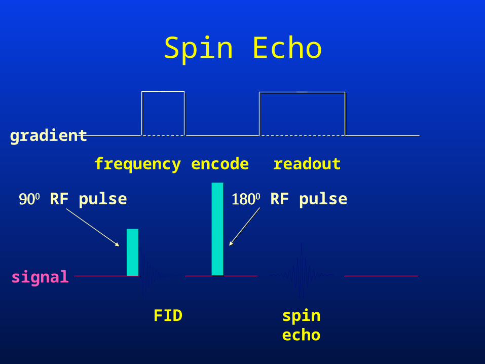
Spin Echo
FID spinecho
RF pulse
readoutfrequency encode
signal
gradient
RF pulse
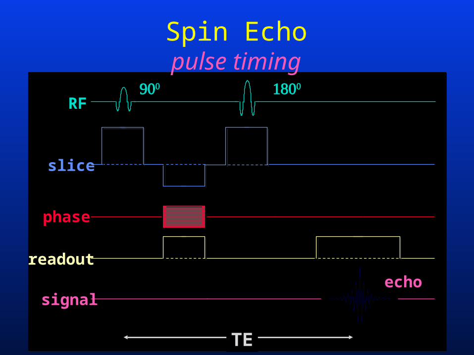
Spin Echopulse timing
echo
RF
signal
readout
phase
slice
TE
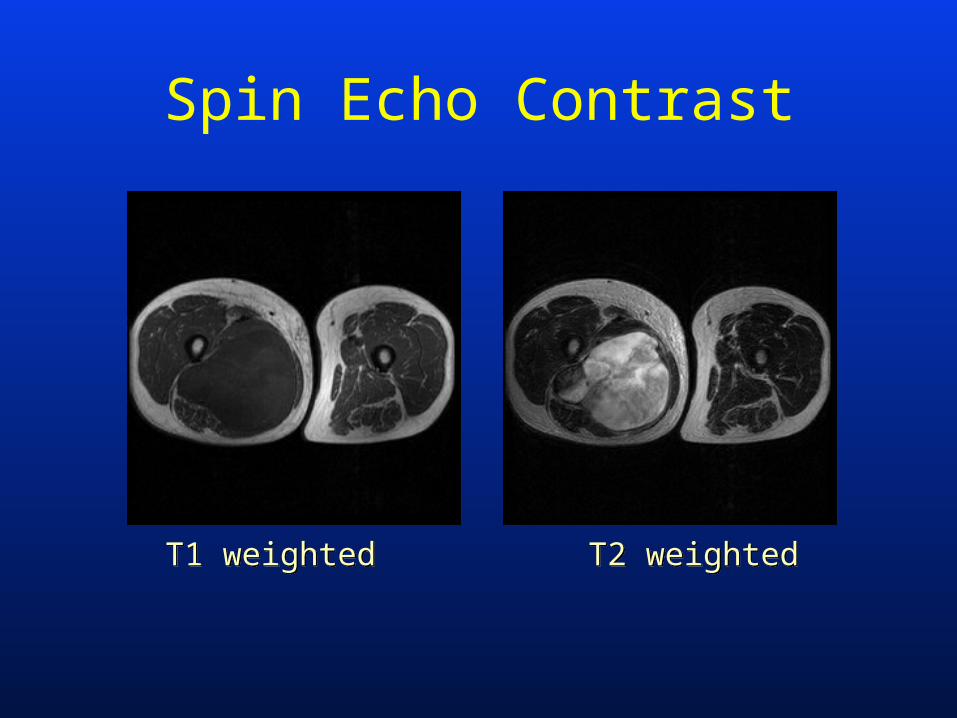
Spin Echo Contrast
T1 weightedT1 weighted T2 weightedT2 weighted
Multi Echo Spin Echorationale
• conventional imaging uses a multi-slice 2D technique– at a given TR time, number of slices depends
on the TE time
T2 weighted imaging:long TR
long TE
PD weighted imaging:long TR
short TE
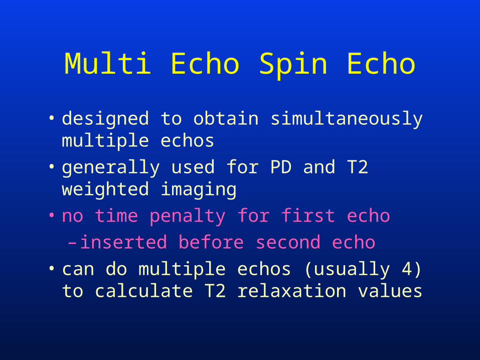
Multi Echo Spin Echo
• designed to obtain simultaneously multiple echos
• generally used for PD and T2 weighted imaging
• no time penalty for first echo
– inserted before second echo
• can do multiple echos (usually 4) to calculate T2 relaxation values
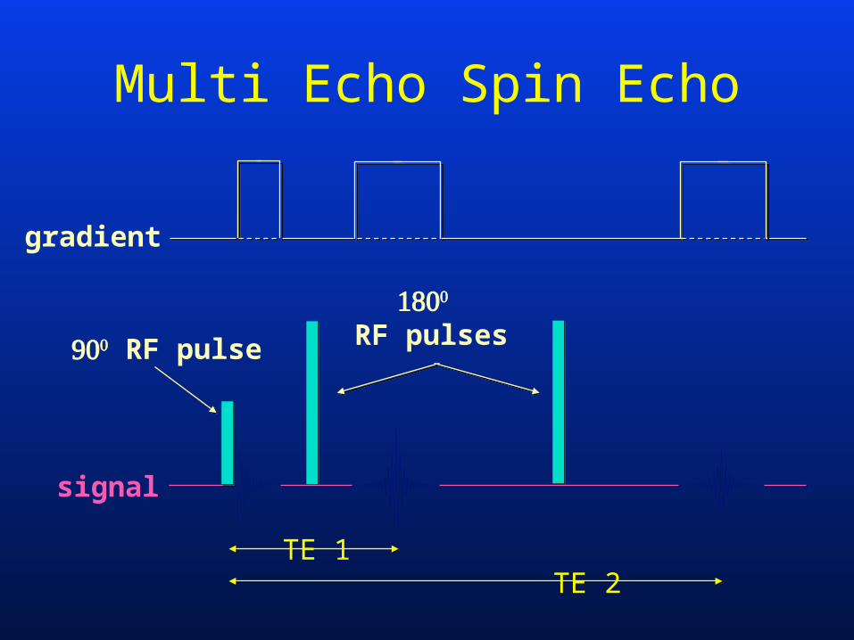
Multi Echo Spin Echo
RF pulse
signal
gradient
RF pulses
TE 1TE 2
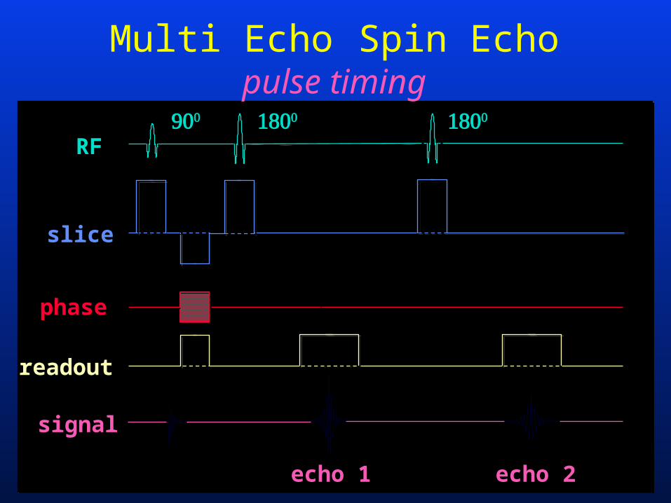
Multi Echo Spin Echopulse timing
echo 2
RF
signal
readout
phase
slice
echo 1
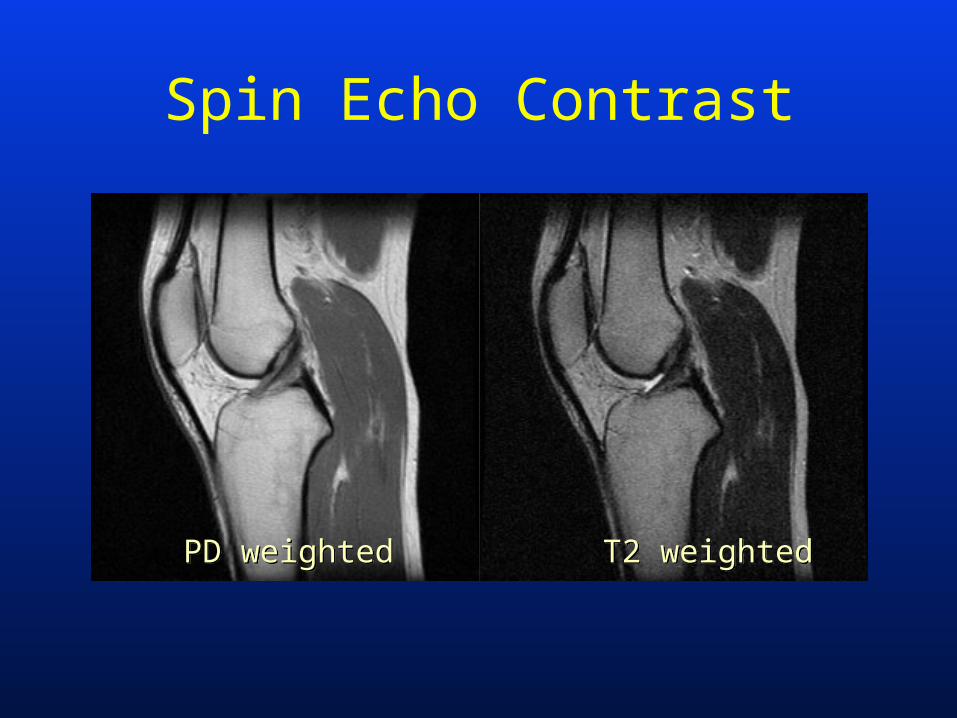
Spin Echo Contrast
PD weightedPD weighted T2 weightedT2 weighted

• Summary– simultaneously generates PD
and T2 weighted images
– no time penalty for acquisition of PD weighted image
– no mis-registration between echos
Multi Echo Spin Echo
Fast Spin Echo
• Rationale – importance of T2 weighted
images• most clinically useful• longest to acquire• lowest S/N
– need for higher spatial resolution
Fast Spin Echohistorical perspective
• faster T2 weighted imaging– gradient echo (T2*)
– reduced data acquisition• “half-NEX”, “half-Fourier” imaging• rectangular FOV• S/N or spatial resolution penalty
– altered flip angle SE imaging• “prise”, “thrift”
Fast Spin Echo
• single most important time limiting factor is the acquisition of enough data to reconstruct an image
• at a given image resolution, the number of phase encodings determines the imaging time
Fast Spin Echo
• each phase encoding is obtained as a unique echo following a single excitation with a 90 degree RF pulse
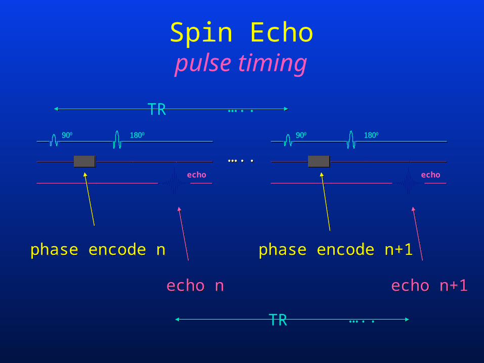
Spin Echopulse timing
…..…..echo
echo
phase encode nphase encode n phase encode n+1phase encode n+1
echo necho n echo n+1echo n+1
TR …..
TR …..
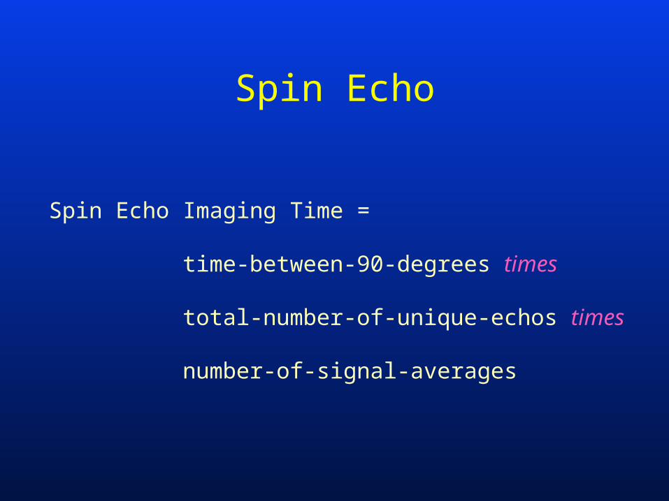
Spin Echo
Spin Echo Imaging Time =
time-between-90-degrees times
total-number-of-unique-echos times
number-of-signal-averages
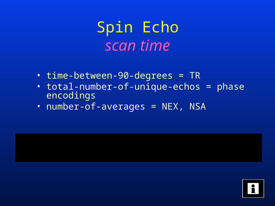
Spin Echoscan time
• time-between-90-degrees = TR• total-number-of-unique-echos = phase encodings• number-of-averages = NEX, NSA
scan timeTR phaseencodings NEX
utesm
minsec
,=
* *60000
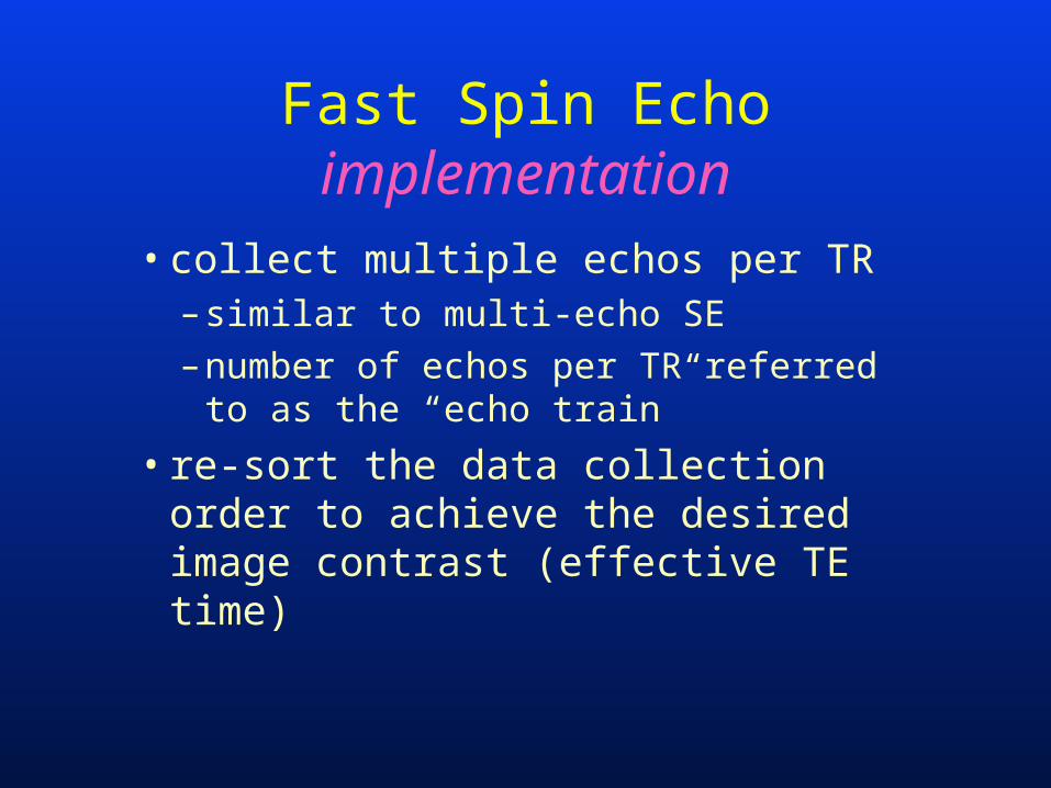
Fast Spin Echoimplementation
• collect multiple echos per TR– similar to multi-echo SE
– number of echos per TR referred to as the “echo train”
• re-sort the data collection order to achieve the desired image contrast (effective TE time)
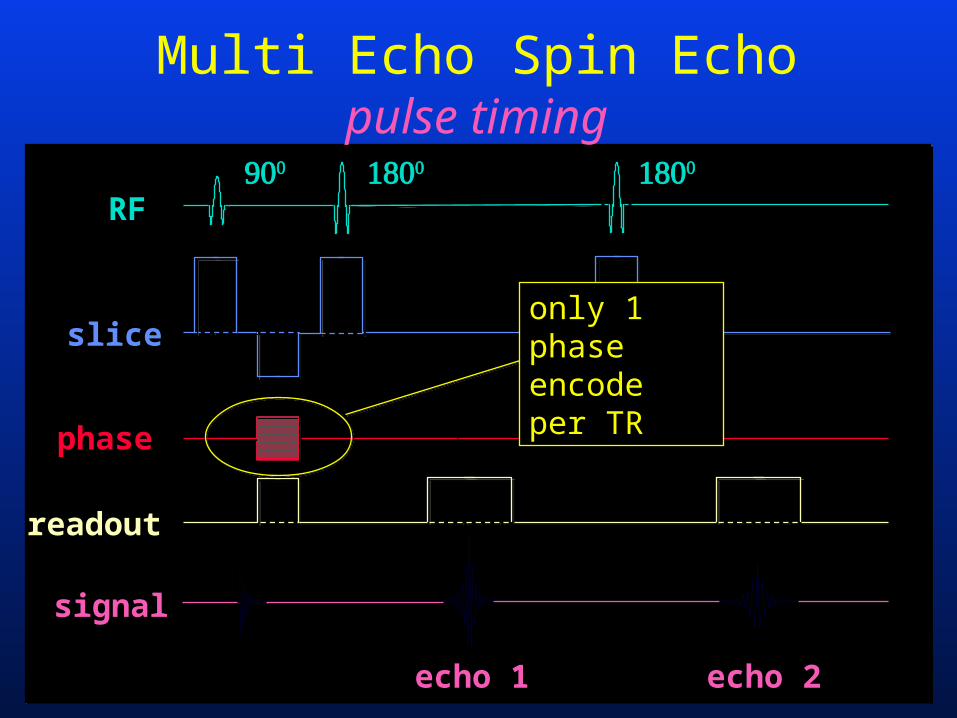
Multi Echo Spin Echopulse timing
echo 2
RF
signal
readout
phase
slice
echo 1
only 1 phase encode per TR
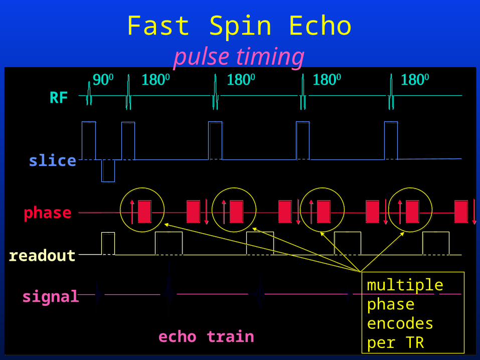
Fast Spin Echopulse timing
RF
signal
readout
phase
slice
echo train
multiple phase encodes per TR
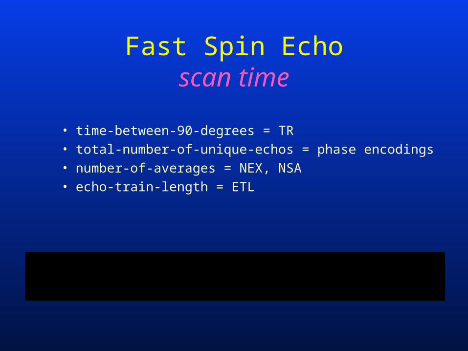
Fast Spin Echoscan time
• time-between-90-degrees = TR• total-number-of-unique-echos = phase encodings• number-of-averages = NEX, NSA• echo-train-length = ETL
scan timeTR phaseencodings NEX
ETLutes
mmin
sec
,=
* **60000
Fast Spin Echoadvantages
• acquisition time reduced proportional to echo train length (ETL)
• can trade-off some of the time savings to improve images– increased NEX
– increased resolution
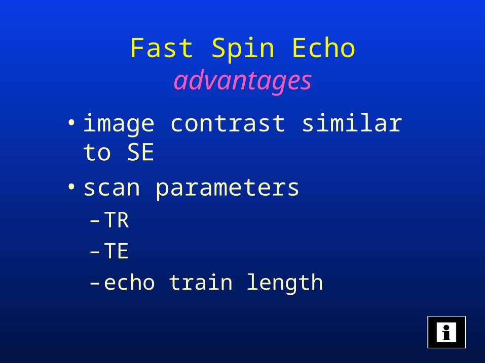
Fast Spin Echoadvantages
• image contrast similar to SE
• scan parameters– TR
– TE
– echo train length
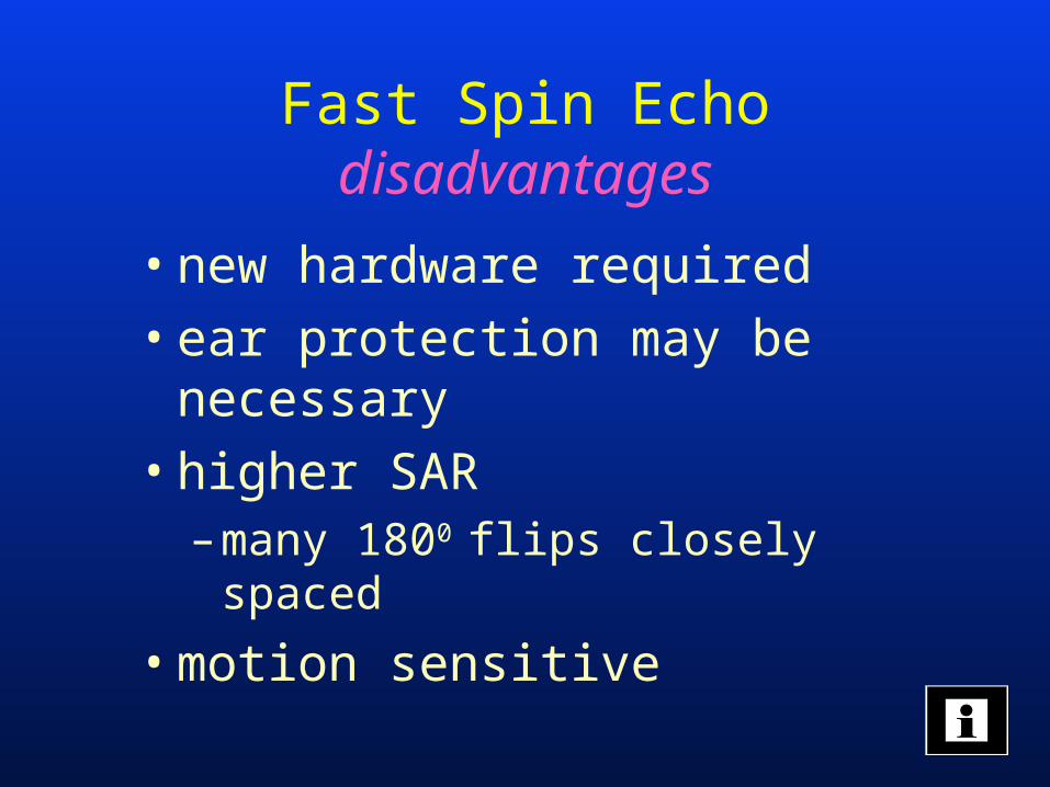
Fast Spin Echodisadvantages
• new hardware required
• ear protection may be necessary
• higher SAR– many 1800 flips closely spaced
• motion sensitive
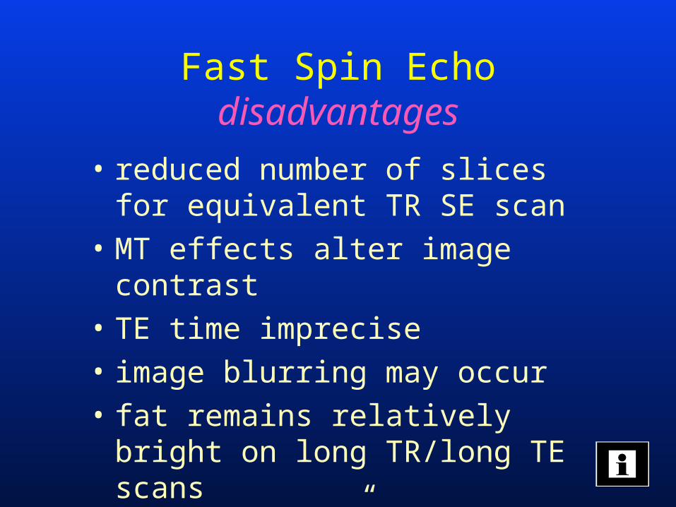
Fast Spin Echodisadvantages
• reduced number of slices for equivalent TR SE scan
• MT effects alter image contrast
• TE time imprecise
• image blurring may occur
• fat remains relatively bright on long TR/long TE scans
• “J-coupling”
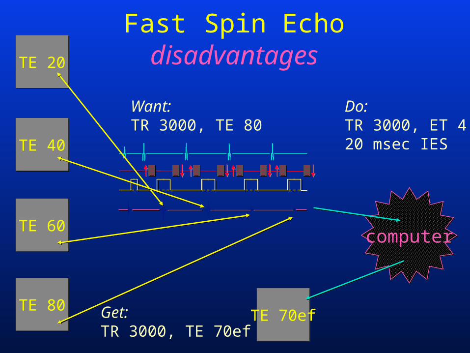
computercomputer
Fast Spin EchodisadvantagesTE 20TE 20
TE 40TE 40
TE 60TE 60
TE 80TE 80TE 70efTE 70ef
Want: TR 3000, TE 80
Do:TR 3000, ET 420 msec IES
Get:TR 3000, TE 70ef
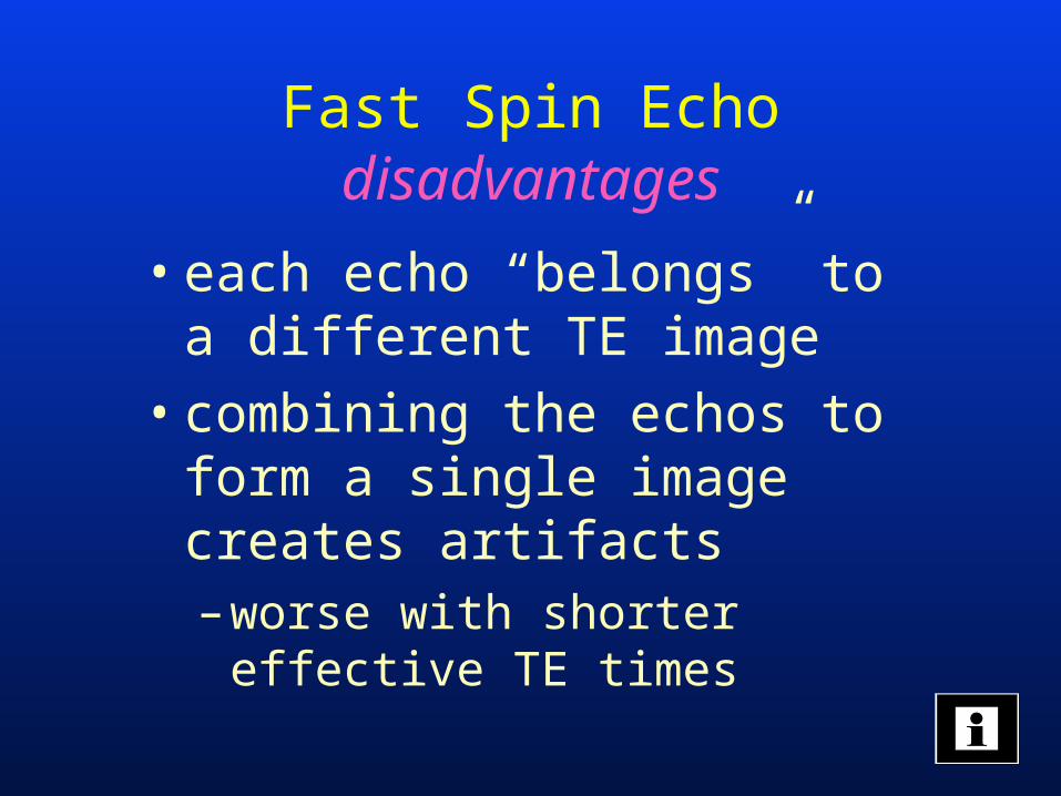
Fast Spin Echodisadvantages
• each echo “belongs” to a different TE image
• combining the echos to form a single image creates artifacts– worse with shorter effective TE
times
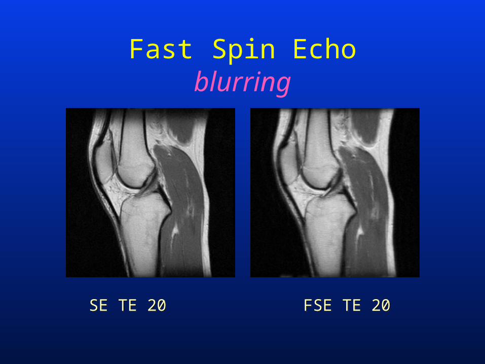
Fast Spin Echoblurring
SE TE 20SE TE 20 FSE TE 20FSE TE 20
Fast Spin Echolimitations
• solutions:– use mainly for T2 weighted imaging
– limit the ET length (~ 8)
– many phase encodes (192 +)
Fast Spin Echolimitations
• solutions:– choose long TE times (> 100 msec)– choose long TR times (> 4000 msec)
• increases fat-fluid contrast
– for PD imaging, –use shorter echo trains (4) and wider
receive bandwidths (32 kHz)–alternatively, use fatsat
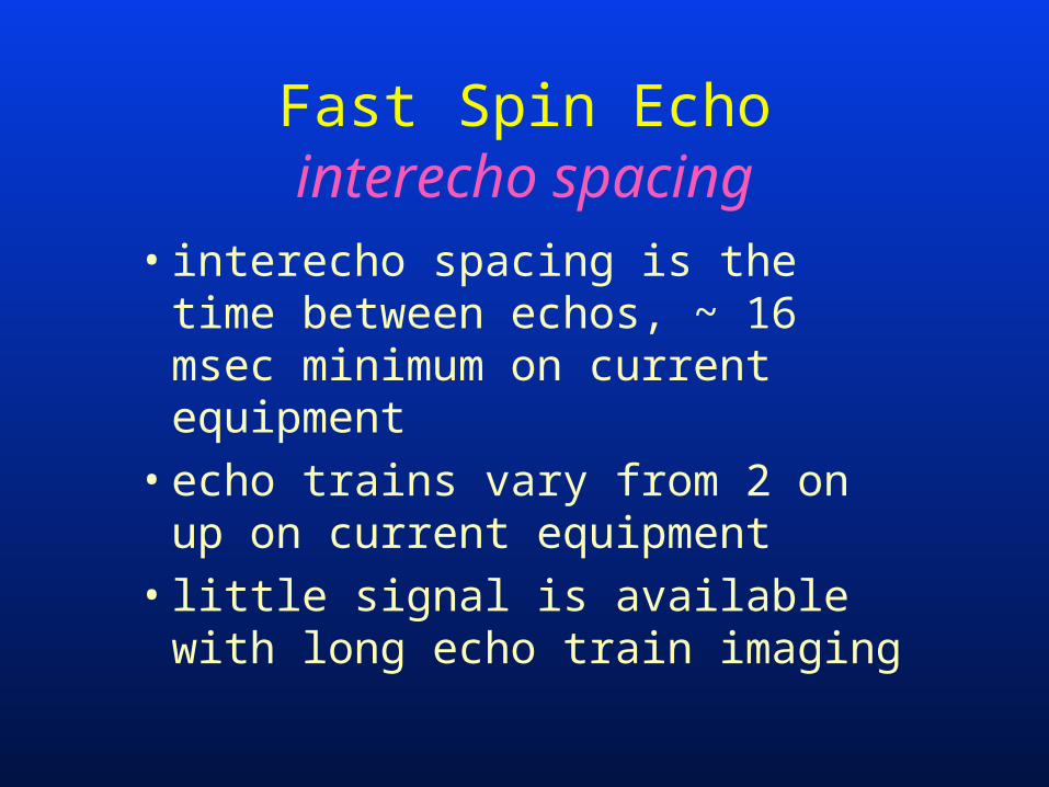
• interecho spacing is the time between echos, ~ 16 msec minimum on current equipment
• echo trains vary from 2 on up on current equipment
• little signal is available with long echo train imaging
Fast Spin Echointerecho spacing
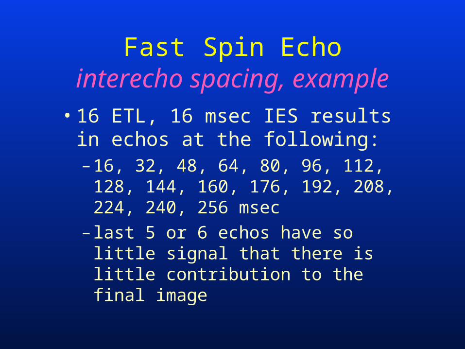
• 16 ETL, 16 msec IES results in echos at the following:– 16, 32, 48, 64, 80, 96, 112, 128,
144, 160, 176, 192, 208, 224, 240, 256 msec
– last 5 or 6 echos have so little signal that there is little contribution to the final image
Fast Spin Echointerecho spacing, example
Fast Spin Echointerecho spacing, example
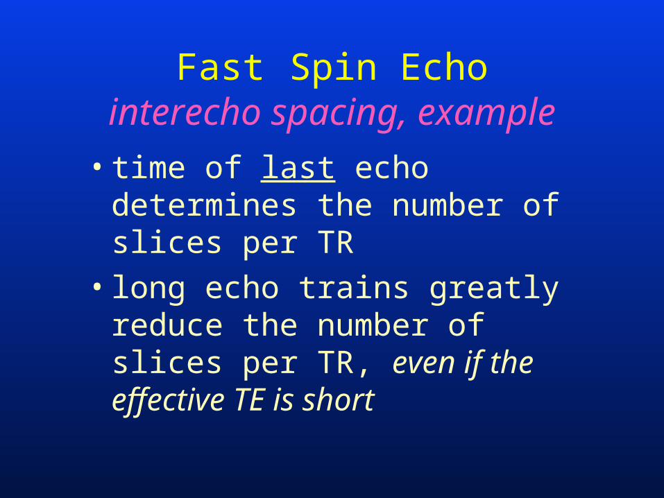
• time of last echo determines the number of slices per TR
• long echo trains greatly reduce the number of slices per TR, even if the effective TE is short
Fast Spin Echointerecho spacing
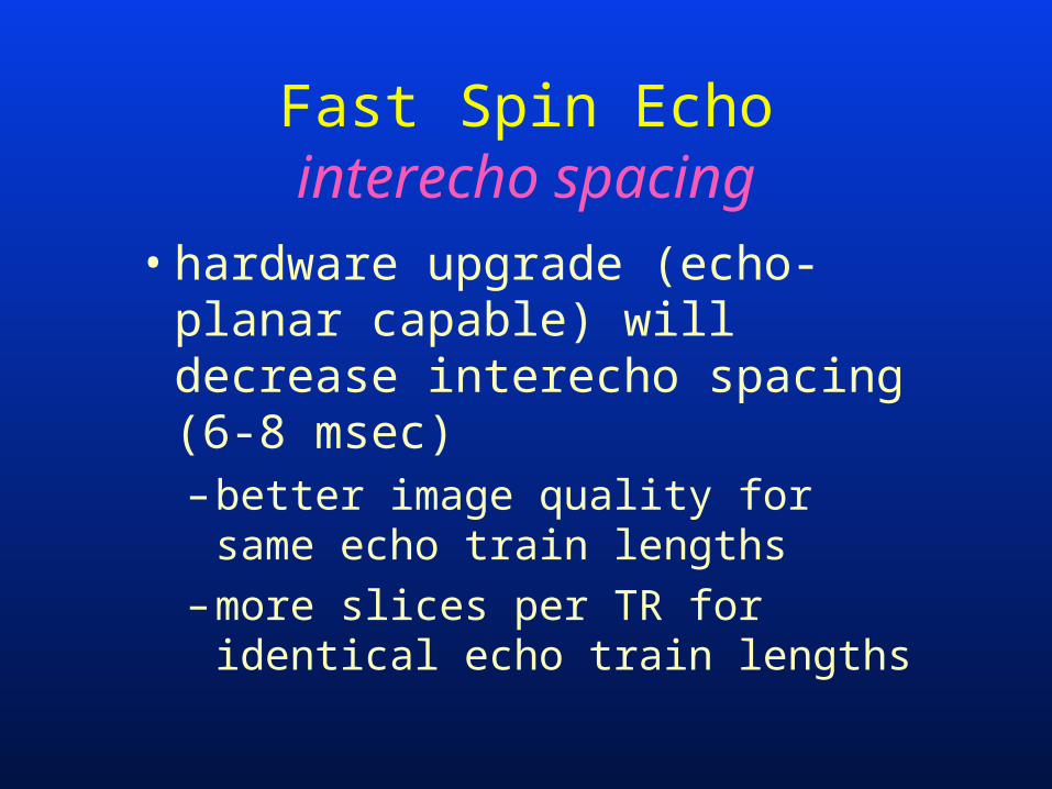
• hardware upgrade (echo-planar capable) will decrease interecho spacing (6-8 msec)– better image quality for same
echo train lengths
– more slices per TR for identical echo train lengths
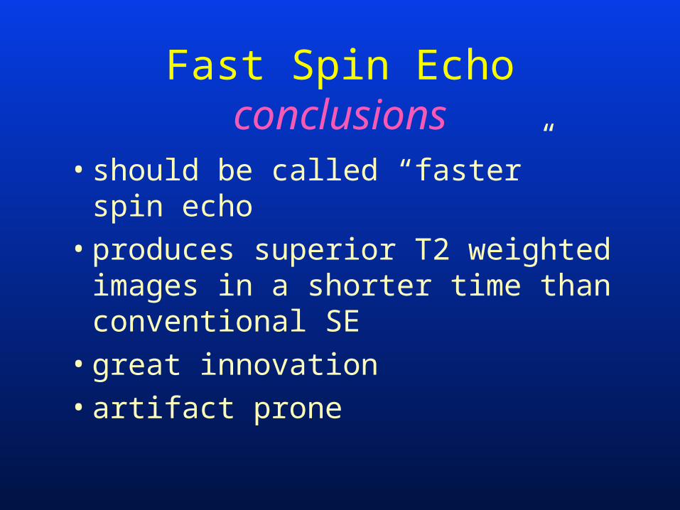
Fast Spin Echoconclusions
• should be called “faster” spin echo
• produces superior T2 weighted images in a shorter time than conventional SE
• great innovation
• artifact prone
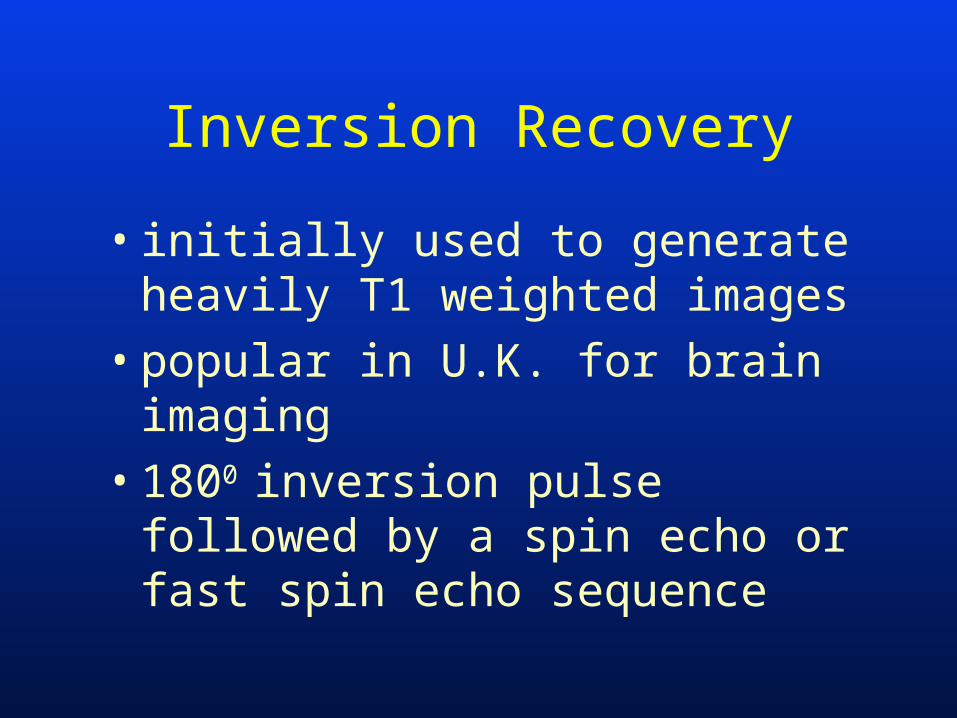
Inversion Recovery
• initially used to generate heavily T1 weighted images
• popular in U.K. for brain imaging
• 1800 inversion pulse followed by a spin echo or fast spin echo sequence
Inversion Recovery
• three image parameters– TI
– TR
– TE
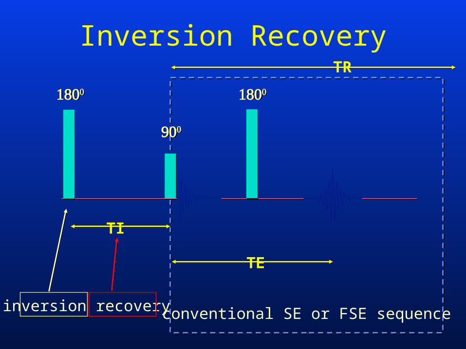
Inversion Recovery
TI
TE
conventional SE or FSE sequenceinversion recovery
TR

Inversion Recovery
-1
-0.8
-0.6
-0.4
-0.2
0
0.2
0.4
0.6
0.8
1
0
25
0
50
0
75
0
10
00
12
50
15
00
TI (msec)
MZ/M0long T1
short T1
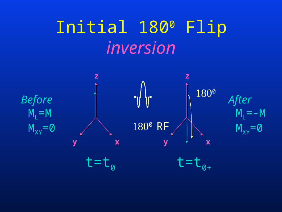
Initial 1800 Flipinversion
z
y x
z
y x
0 RF
t=t0 t=t0+
0
AfterML=-MMXY=0
BeforeML=MMXY=0
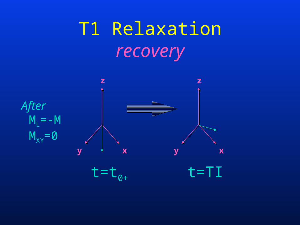
T1 Relaxationrecovery
z
y x
z
y x
t=t0+ t=TI
AfterML=-MMXY=0
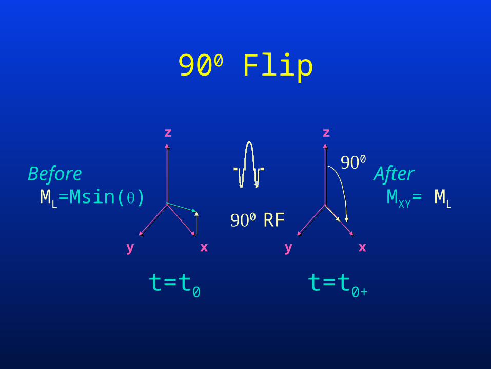
900 Flip
z
y x
z
y x
0 RF
t=t0 t=t0+
0
AfterMXY= ML
BeforeML=Msin()
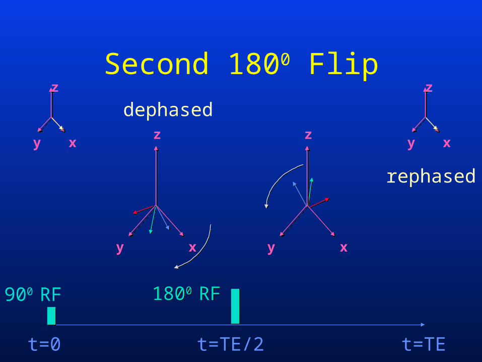
z
y xz
y x
z
y x
z
y x
t=TE/2 t=TEt=0
900 RF
dephased
rephased
Second 1800 Flip
1800 RF1800 RF
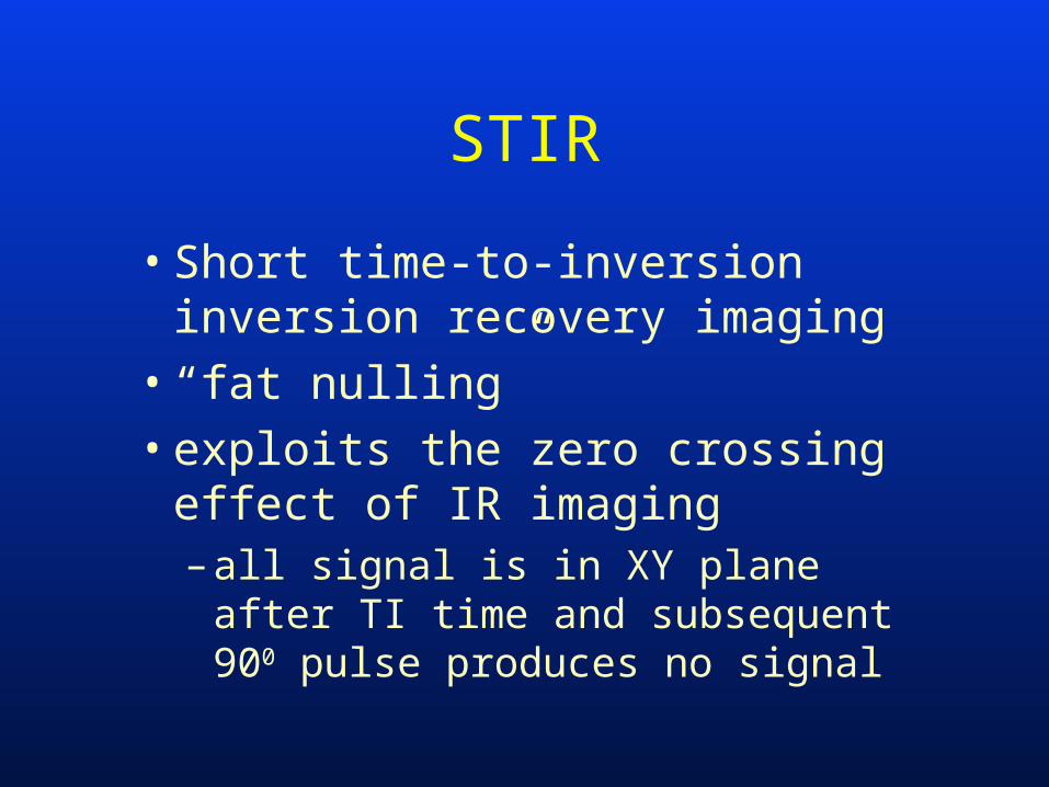
STIR
• Short time-to-inversion inversion recovery imaging
• “fat nulling”• exploits the zero crossing effect of
IR imaging– all signal is in XY plane after TI time
and subsequent 900 pulse produces no signal
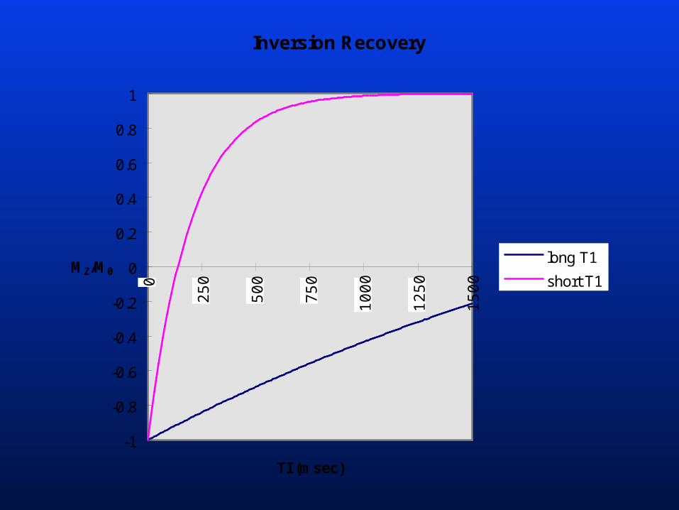
Inversion Recovery
-1
-0.8
-0.6
-0.4
-0.2
0
0.2
0.4
0.6
0.8
1
0
25
0
50
0
75
0
10
00
12
50
15
00
TI (msec)
MZ/M0long T1
short T1
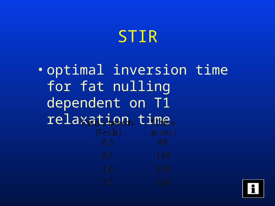
STIR
• optimal inversion time for fat nulling dependent on T1 relaxation time
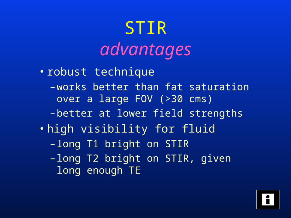
STIRadvantages
• robust technique– works better than fat saturation over
a large FOV (>30 cms)
– better at lower field strengths
• high visibility for fluid– long T1 bright on STIR
– long T2 bright on STIR, given long enough TE
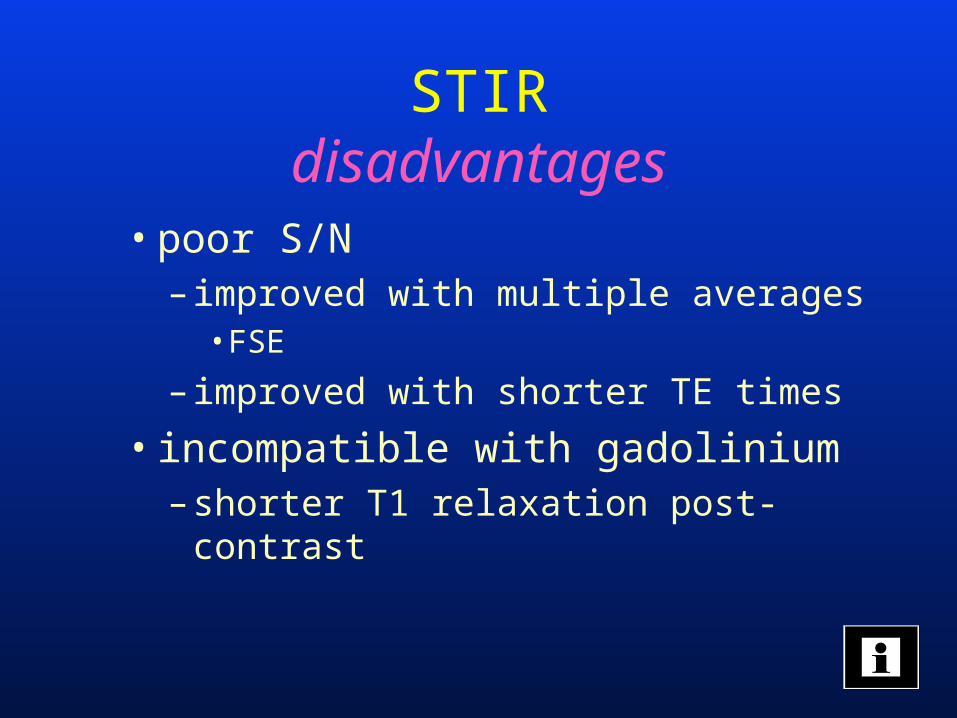
• poor S/N– improved with multiple averages
• FSE
– improved with shorter TE times
• incompatible with gadolinium– shorter T1 relaxation post-contrast
STIRdisadvantages
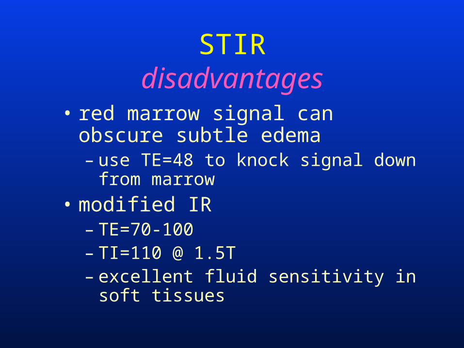
• red marrow signal can obscure subtle edema– use TE=48 to knock signal down from
marrow
• modified IR– TE=70-100– TI=110 @ 1.5T– excellent fluid sensitivity in soft tissues
STIRdisadvantages
Summary
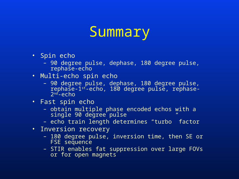
• Spin echo– 90 degree pulse, dephase, 180 degree pulse, rephase-
echo• Multi-echo spin echo
– 90 degree pulse, dephase, 180 degree pulse, rephase-1st-echo, 180 degree pulse, rephase-2nd-echo
• Fast spin echo– obtain multiple phase encoded echos with a single 90
degree pulse– echo train length determines “turbo” factor
• Inversion recovery– 180 degree pulse, inversion time, then SE or FSE
sequence– STIR enables fat suppression over large FOVs or for open
magnets

![Concepts and Engineering Aspects of a Neutron Resonance Spin … · 2014. 4. 23. · Neutron Resonance Spin-Echo (NRSE) [1,2] is an alternative to the conventional Neutron Spin-Echo](https://static.fdocuments.in/doc/165x107/610964ceb9a53a05954102e6/concepts-and-engineering-aspects-of-a-neutron-resonance-spin-2014-4-23-neutron.jpg)