IMAGING AND CHARACTERIZATION OF FACIAL STRAIN IN LONG ...
4
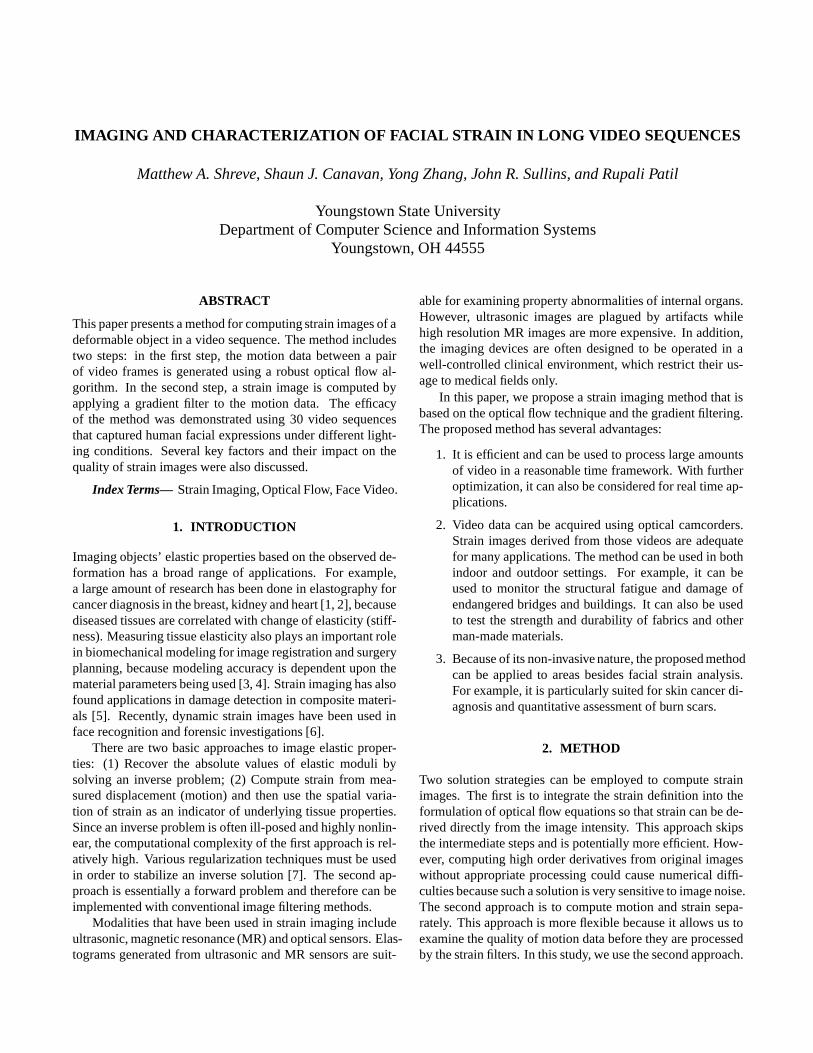
IMAGING AND CHARACTERIZATION OF FACIAL STRAIN IN LONG VIDEO SEQUENCES Matthew A. Shreve, Shaun J. Canavan, Yong Zhang, John R. Sullins, and Rupali Patil Youngstown State University Department of Computer Science and Information Systems Youngstown, OH 44555 ABSTRACT This paper presents a method for computing strain images of a deformable object in a video sequence. The method includes two steps: in the first step, the motion data between a pair of video frames is generated using a robust optical flow al- gorithm. In the second step, a strain image is computed by applying a gradient filter to the motion data. The efficacy of the method was demonstrated using 30 video sequences that captured human facial expressions under different light- ing conditions. Several key factors and their impact on the quality of strain images were also discussed. Index Terms— Strain Imaging, Optical Flow, Face Video. 1. INTRODUCTION Imaging objects’ elastic properties based on the observed de- formation has a broad range of applications. For example, a large amount of research has been done in elastography for cancer diagnosis in the breast, kidney and heart [1, 2], because diseased tissues are correlated with change of elasticity (stiff- ness). Measuring tissue elasticity also plays an important role in biomechanical modeling for image registration and surgery planning, because modeling accuracy is dependent upon the material parameters being used [3, 4]. Strain imaging has also found applications in damage detection in composite materi- als [5]. Recently, dynamic strain images have been used in face recognition and forensic investigations [6]. There are two basic approaches to image elastic proper- ties: (1) Recover the absolute values of elastic moduli by solving an inverse problem; (2) Compute strain from mea- sured displacement (motion) and then use the spatial varia- tion of strain as an indicator of underlying tissue properties. Since an inverse problem is often ill-posed and highly nonlin- ear, the computational complexity of the first approach is rel- atively high. Various regularization techniques must be used in order to stabilize an inverse solution [7]. The second ap- proach is essentially a forward problem and therefore can be implemented with conventional image filtering methods. Modalities that have been used in strain imaging include ultrasonic, magnetic resonance (MR) and optical sensors. Elas- tograms generated from ultrasonic and MR sensors are suit- able for examining property abnormalities of internal organs. However, ultrasonic images are plagued by artifacts while high resolution MR images are more expensive. In addition, the imaging devices are often designed to be operated in a well-controlled clinical environment, which restrict their us- age to medical fields only. In this paper, we propose a strain imaging method that is based on the optical flow technique and the gradient filtering. The proposed method has several advantages: 1. It is efficient and can be used to process large amounts of video in a reasonable time framework. With further optimization, it can also be considered for real time ap- plications. 2. Video data can be acquired using optical camcorders. Strain images derived from those videos are adequate for many applications. The method can be used in both indoor and outdoor settings. For example, it can be used to monitor the structural fatigue and damage of endangered bridges and buildings. It can also be used to test the strength and durability of fabrics and other man-made materials. 3. Because of its non-invasive nature, the proposed method can be applied to areas besides facial strain analysis. For example, it is particularly suited for skin cancer di- agnosis and quantitative assessment of burn scars. 2. METHOD Two solution strategies can be employed to compute strain images. The first is to integrate the strain definition into the formulation of optical flow equations so that strain can be de- rived directly from the image intensity. This approach skips the intermediate steps and is potentially more efficient. How- ever, computing high order derivatives from original images without appropriate processing could cause numerical diffi- culties because such a solution is very sensitive to image noise. The second approach is to compute motion and strain sepa- rately. This approach is more flexible because it allows us to examine the quality of motion data before they are processed by the strain filters. In this study, we use the second approach.
Transcript of IMAGING AND CHARACTERIZATION OF FACIAL STRAIN IN LONG ...
IMAGING AND CHARACTERIZATION OF FACIAL STRAIN IN LONG VIDEO SEQUENCES
Matthew A. Shreve, Shaun J. Canavan, Yong Zhang, John R. Sullins, and Rupali Patil
Youngstown State UniversityDepartment of Computer Science and Information Systems
Youngstown, OH 44555
ABSTRACT
This paper presents a method for computing strain images of adeformable object in a video sequence. The method includestwo steps: in the first step, the motion data between a pairof video frames is generated using a robust optical flow al-gorithm. In the second step, a strain image is computed byapplying a gradient filter to the motion data. The efficacyof the method was demonstrated using 30 video sequencesthat captured human facial expressions under different light-ing conditions. Several key factors and their impact on thequality of strain images were also discussed.
Index Terms— Strain Imaging, Optical Flow, Face Video.
1. INTRODUCTION
Imaging objects’ elastic properties based on the observed de-formation has a broad range of applications. For example,a large amount of research has been done in elastography forcancer diagnosis in the breast, kidney and heart [1, 2], becausediseased tissues are correlated with change of elasticity (stiff-ness). Measuring tissue elasticity also plays an important rolein biomechanical modeling for image registration and surgeryplanning, because modeling accuracy is dependent upon thematerial parameters being used [3, 4]. Strain imaging has alsofound applications in damage detection in composite materi-als [5]. Recently, dynamic strain images have been used inface recognition and forensic investigations [6].
There are two basic approaches to image elastic proper-ties: (1) Recover the absolute values of elastic moduli bysolving an inverse problem; (2) Compute strain from mea-sured displacement (motion) and then use the spatial varia-tion of strain as an indicator of underlying tissue properties.Since an inverse problem is often ill-posed and highly nonlin-ear, the computational complexity of the first approach is rel-atively high. Various regularization techniques must be usedin order to stabilize an inverse solution [7]. The second ap-proach is essentially a forward problem and therefore can beimplemented with conventional image filtering methods.
Modalities that have been used in strain imaging includeultrasonic, magnetic resonance (MR) and optical sensors. Elas-tograms generated from ultrasonic and MR sensors are suit-
able for examining property abnormalities of internal organs.However, ultrasonic images are plagued by artifacts whilehigh resolution MR images are more expensive. In addition,the imaging devices are often designed to be operated in awell-controlled clinical environment, which restrict their us-age to medical fields only.
In this paper, we propose a strain imaging method that isbased on the optical flow technique and the gradient filtering.The proposed method has several advantages:
1. It is efficient and can be used to process large amountsof video in a reasonable time framework. With furtheroptimization, it can also be considered for real time ap-plications.
2. Video data can be acquired using optical camcorders.Strain images derived from those videos are adequatefor many applications. The method can be used in bothindoor and outdoor settings. For example, it can beused to monitor the structural fatigue and damage ofendangered bridges and buildings. It can also be usedto test the strength and durability of fabrics and otherman-made materials.
3. Because of its non-invasive nature, the proposed methodcan be applied to areas besides facial strain analysis.For example, it is particularly suited for skin cancer di-agnosis and quantitative assessment of burn scars.
2. METHOD
Two solution strategies can be employed to compute strainimages. The first is to integrate the strain definition into theformulation of optical flow equations so that strain can be de-rived directly from the image intensity. This approach skipsthe intermediate steps and is potentially more efficient. How-ever, computing high order derivatives from original imageswithout appropriate processing could cause numerical diffi-culties because such a solution is very sensitive to image noise.The second approach is to compute motion and strain sepa-rately. This approach is more flexible because it allows us toexamine the quality of motion data before they are processedby the strain filters. In this study, we use the second approach.
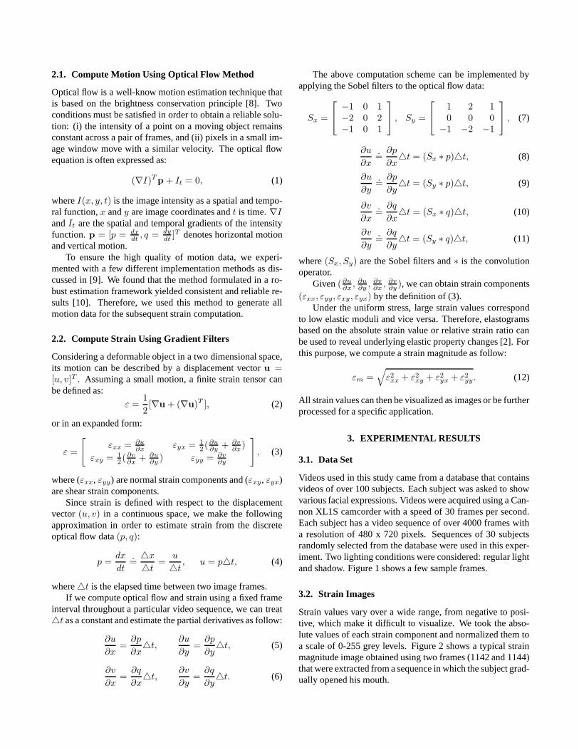
2.1. Compute Motion Using Optical Flow Method
Optical flow is a well-know motion estimation technique thatis based on the brightness conservation principle [8]. Twoconditions must be satisfied in order to obtain a reliable solu-tion: (i) the intensity of a point on a moving object remainsconstant across a pair of frames, and (ii) pixels in a small im-age window move with a similar velocity. The optical flowequation is often expressed as:
(∇I)Tp + It = 0, (1)
where I(x, y, t) is the image intensity as a spatial and tempo-ral function, x and y are image coordinates and t is time. ∇I
and It are the spatial and temporal gradients of the intensityfunction. p = [p = dx
dt, q = dy
dt]T denotes horizontal motion
and vertical motion.To ensure the high quality of motion data, we experi-
mented with a few different implementation methods as dis-cussed in [9]. We found that the method formulated in a ro-bust estimation framework yielded consistent and reliable re-sults [10]. Therefore, we used this method to generate allmotion data for the subsequent strain computation.
2.2. Compute Strain Using Gradient Filters
Considering a deformable object in a two dimensional space,its motion can be described by a displacement vector u =[u, v]T . Assuming a small motion, a finite strain tensor canbe defined as:
ε =1
2[∇u + (∇u)T ], (2)
or in an expanded form:
ε =
[
εxx = ∂u∂x
εyx = 1
2(∂u
∂y+ ∂v
∂x)
εxy = 1
2( ∂v
∂x+ ∂u
∂y) εyy = ∂v
∂y
]
, (3)
where (εxx, εyy) are normal strain components and (εxy, εyx)are shear strain components.
Since strain is defined with respect to the displacementvector (u, v) in a continuous space, we make the followingapproximation in order to estimate strain from the discreteoptical flow data (p, q):
p =dx
dt
.=4x
4t=
u
4t, u = p4t, (4)
where4t is the elapsed time between two image frames.If we compute optical flow and strain using a fixed frame
interval throughout a particular video sequence, we can treat4t as a constant and estimate the partial derivatives as follow:
∂u
∂x=
∂p
∂x4t,
∂u
∂y=
∂p
∂y4t, (5)
∂v
∂x=
∂q
∂x4t,
∂v
∂y=
∂q
∂y4t. (6)
The above computation scheme can be implemented byapplying the Sobel filters to the optical flow data:
Sx =
−1 0 1−2 0 2−1 0 1
, Sy =
1 2 10 0 0
−1 −2 −1
, (7)
∂u
∂x
.=
∂p
∂x4t = (Sx ∗ p)4t, (8)
∂u
∂y
.=
∂p
∂y4t = (Sy ∗ p)4t, (9)
∂v
∂x
.=
∂q
∂x4t = (Sx ∗ q)4t, (10)
∂v
∂y
.=
∂q
∂y4t = (Sy ∗ q)4t, (11)
where (Sx, Sy) are the Sobel filters and ∗ is the convolutionoperator.
Given (∂u∂x
, ∂u∂y
, ∂v∂x
, ∂v∂y
), we can obtain strain components(εxx, εyy, εxy, εyx) by the definition of (3).
Under the uniform stress, large strain values correspondto low elastic moduli and vice versa. Therefore, elastogramsbased on the absolute strain value or relative strain ratio canbe used to reveal underlying elastic property changes [2]. Forthis purpose, we compute a strain magnitude as follow:
εm =√
ε2xx + ε2
xy + ε2yx + ε2
yy. (12)
All strain values can then be visualized as images or be furtherprocessed for a specific application.
3. EXPERIMENTAL RESULTS
3.1. Data Set
Videos used in this study came from a database that containsvideos of over 100 subjects. Each subject was asked to showvarious facial expressions. Videos were acquired using a Can-non XL1S camcorder with a speed of 30 frames per second.Each subject has a video sequence of over 4000 frames witha resolution of 480 x 720 pixels. Sequences of 30 subjectsrandomly selected from the database were used in this exper-iment. Two lighting conditions were considered: regular lightand shadow. Figure 1 shows a few sample frames.
3.2. Strain Images
Strain values vary over a wide range, from negative to posi-tive, which make it difficult to visualize. We took the abso-lute values of each strain component and normalized them toa scale of 0-255 grey levels. Figure 2 shows a typical strainmagnitude image obtained using two frames (1142 and 1144)that were extracted from a sequence in which the subject grad-ually opened his mouth.

(a) Regular Light (b) Shadow
(c) Regular Light (d) Shadow
Fig. 1. Videos acquired under different lighting conditions.
Motion between the two frames occurred mainly in thelower portion of the face, which was clearly captured in (Fig-ure 2 (d)), while the horizontal motion was almost negligible.Note that the bright pixels along the right boundary in Figure2 (c) are noise and were not used in strain computation. As aresult, the lower portion of the face has large strain values,while the background has small random strain values only(Figure 2 (e)). As can be seen in the zoomed-in view (Figure2 (f)), strain distribution of skin is smooth and continuous, acharacteristic of deformed soft tissues.
On the other hand, strain discontinuities were observedalong the lips and the jaw line. We call this type of strainpseudo strain, because it has no connection with true elastic-ity. Instead, it is caused by the brightness contrast betweenthe background and a moving object. The pseudo strain canalso be observed when a subject suddenly shakes his/her heador blinks his/her eyes.
4. DISCUSSIONS
The quality of a strain image can be affected by many factors,including those commonly encountered in imaging problems.We discuss two key factors by means of both visual examina-tion and quantitative measures.
4.1. Frame Interval
Because of the small motion constraint imposed on the opticalflow equation, the interval between two frames has a strongimpact on the quality of motion data, which in turn will effectthe quality of strain images.
Figure 3 shows three strain magnitude images using framepairs of increasing intervals. As expected, strain deterioratedrapidly as the interval increased, and eventually became mean-ingless when the interval was greater than 5. To provide morequantitative descriptions, we computed a strain difference (SD)
(a) Frame 1142 (b) Frame 1144
(c) Horizontal Motion (u) (d) Vertical Motion (v)
(e) Strain Magnitude (f) Zoomed-in view
Fig. 2. Examples of optical flow and strain images.
between two images that have interval m and interval n:
SD =
ROI∑
i=0
(Sint=m(i)− Sint=n(i))2, (13)
where ROI is a selected region of interest and S represents astrain component.
Since a frame interval of 2 usually yields good strain re-sults, we took a strain image (interval = 2) as the base im-age, and then computed the differences between the base im-age and a series of strain images with intervals from 1 to 8.The results were plotted in Figure 4. It is clear that all straincomponents show marked deviation from the base image. Itshould be pointed out that frame interval is closely related tothe video capture speed, and therefore an optimal interval isreally task-dependent.
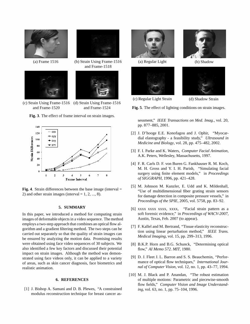
4.2. Lighting Condition
It is interesting to notice that lighting conditions do not causesignificant deterioration of strain quality, even when severeshadows are present as shown in Figure 5 (b). The overallfacial strain pattern was preserved except in a few areas thathave strong light reflections caused by hair, beard, earrings,or eye glasses. This may be partially explained by the factthat strain (and optical flow) is more dependent upon the rela-tive change of intensity between two frames than the absoluteintensity values.
(a) Frame 1516 (b) Strain Using Frame-1516and Frame-1518
(c) Strain Using Frame-1516and Frame-1520
(d) Strain Using Frame-1516and Frame-1524
Fig. 3. The effect of frame interval on strain images.
Fig. 4. Strain differences between the base image (interval =2) and other strain images (interval = 1, 2, ..., 8).
5. SUMMARY
In this paper, we introduced a method for computing strainimages of deformable objects in a video sequence. The methodemploys a two-step approach that combines an optical flow al-gorithm and a gradient filtering method. The two steps can becarried out separately so that the quality of strain images canbe ensured by analyzing the motion data. Promising resultswere obtained using face video sequences of 30 subjects. Wealso identified a few key factors and discussed their potentialimpact on strain images. Although the method was demon-strated using face videos only, it can be applied to a varietyof areas, such as skin cancer diagnosis, face biometrics andrealistic animation.
6. REFERENCES
[1] J. Bishop A. Samani and D. B. Plewes, “A constrainedmodulus reconstruction technique for breast cancer as-
(a) Regular Light (b) Shadow
(c) Regular Light Strain (d) Shadow Strain
Fig. 5. The effect of lighting conditions on strain images.
sessment,” IEEE Transactions on Med. Imag., vol. 20,pp. 877–885, 2001.
[2] J. D’hooge E.E. Konofagou and J. Ophir, “Myocar-dial elastography - a feasibility study,” Ultrasound inMedicine and Biology, vol. 28, pp. 475–482, 2002.
[3] F. I. Parke and K. Waters, Computer Facial Animation,A.K. Peters, Wellesley, Massachusetts, 1997.
[4] F. R. Carls D. F. von Buren G. Fankhauser R. M. Koch,M. H. Gross and Y. I. H. Parish, “Simulating facialsurgery using finite element models,” in Proceedingsof SIGGRAPH, 1996, pp. 421–428.
[5] M. Johnson M. Kunzler, E. Udd and K. Mildenhall,“Use of multidimensional fiber grating strain sensorsfor damage detection in composite pressure vessels,” inProceedings of the SPIE, 2005, vol. 5758, pp. 83–92.
[6] xxxx xxxx xxxx, xxxx, “Facial strain pattern as asoft forensic evidence,” in Proceedings of WACV-2007,Austin, Texas, Feb. 2007 (to appear).
[7] F. Kallel and M. Bertrand, “Tissue elasticity reconstruc-tion using linear perturbation method,” IEEE Trans.Medical Imaging, vol. 15, pp. 299–313, 1996.
[8] B.K.P. Horn and B.G. Schunck, “Determining opticalflow,” AI Memo 572. MIT, 1980.
[9] D. J. Fleet J. L. Barron and S. S. Beauchemin, “Perfor-mance of optical flow techniques,” International Jour-nal of Computer Vision, vol. 12, no. 1, pp. 43–77, 1994.
[10] M. J. Black and P. Anandan, “The robust estimationof multiple motions: Parametric and piecewise-smoothflow fields,” Computer Vision and Image Understand-ing, vol. 63, no. 1, pp. 75–104, 1996.