ImageJ 1 - cdn.prod-carehubs.net · The ImageJ User Guide 1.44 Tiago F erreira ¥ W ayne Rasband F...
199
ImageJ 1.44 User Guide
Transcript of ImageJ 1 - cdn.prod-carehubs.net · The ImageJ User Guide 1.44 Tiago F erreira ¥ W ayne Rasband F...
ImageJ 1.44User Guide

The ImageJ User Guide1.44
Tiago Ferreira • Wayne Rasband
February 9, 2011
Note
This document is highly enriched in hypertext links and was thought as afully-searchable, self-contained, annotatable, o!ine manual (cf. ConventionsUsed in This Guide).Given ImageJ’s heavy development this guide will always remain an unfin-ished draft and should be considered complementary to the remaining ImageJdocumentation resources (cf. Getting Help). As such, all ImageJ users anddevelopers are encouraged to contribute to future editions of this manual (seeAbout This Guide).The latest version of this document can always be obtained from http://imagej.nih.gov/ij/docs/user-guide.pdf. A HTML version is also availableonline at http://imagej.nih.gov/ij/docs/guide/ or as a downloadable ZIParchive.

Contents
Release Notes For ImageJ 1.44 viii
Noteworthy ix
Macro Listings x
Conventions Used in This Guide xi
I Getting Started 1
1 What is ImageJ? 1
2 Installation 1
3 Maintaining ImageJ 2
4 Getting Help 4
II Working with ImageJ 6
5 Shortcuts and Modifier Keys 6
6 Finding Commands 7
7 Undo and Redo 8
8 Image Types and Image Formats 8
9 Stacks, Virtual Stacks and Hyperstacks 11
10 Color Images 13
11 Selections 16
12 Settings and Preferences 18
III Extending ImageJ 20
13 Macros 20
14 Scripts 21
15 Plugins 22
iii

16 Scripting in Other Languages 23
17 Running ImageJ From the Command Line 24
18 ImageJ Interoperability 25
IV The ImageJ User Interface 26
19 Tools 2819.1 Rectangular Selection Tool . . . . . . . . . . . . . . . . . . . . . . . . . . 2819.2 Round Rectangular Selection Tool . . . . . . . . . . . . . . . . . . . . . . 2819.3 Oval Selection Tool . . . . . . . . . . . . . . . . . . . . . . . . . . . . . . 2819.4 Elliptical Selection Tool . . . . . . . . . . . . . . . . . . . . . . . . . . . . 2919.5 Brush Selection Tool . . . . . . . . . . . . . . . . . . . . . . . . . . . . . 2919.6 Polygon Selection Tool . . . . . . . . . . . . . . . . . . . . . . . . . . . . 2919.7 Freehand Selection Tool . . . . . . . . . . . . . . . . . . . . . . . . . . . 2919.8 Wand Tool . . . . . . . . . . . . . . . . . . . . . . . . . . . . . . . . . . . 3019.9 Line Selection Tools . . . . . . . . . . . . . . . . . . . . . . . . . . . . . . 3119.10 Arrow Tool . . . . . . . . . . . . . . . . . . . . . . . . . . . . . . . . . . . 3119.11 Angle Tool . . . . . . . . . . . . . . . . . . . . . . . . . . . . . . . . . . . 3219.12 Point Tool . . . . . . . . . . . . . . . . . . . . . . . . . . . . . . . . . . . 3219.13 Multi-point Tool . . . . . . . . . . . . . . . . . . . . . . . . . . . . . . . . 3319.14 Text Tool . . . . . . . . . . . . . . . . . . . . . . . . . . . . . . . . . . . 3319.15 Magnifying Glass . . . . . . . . . . . . . . . . . . . . . . . . . . . . . . . 3419.16 Scrolling Tool . . . . . . . . . . . . . . . . . . . . . . . . . . . . . . . . . 3419.17 Color Picker . . . . . . . . . . . . . . . . . . . . . . . . . . . . . . . . . . 3419.18 Macro Toolset Switcher . . . . . . . . . . . . . . . . . . . . . . . . . . . . 3519.19 Macro Tools . . . . . . . . . . . . . . . . . . . . . . . . . . . . . . . . . . 35
20 Contextual Menu 35
21 The Results Table 37
22 The ImageJ Editor 38
V ImageJ Commands 41
23 File ! 4123.1 New ! . . . . . . . . . . . . . . . . . . . . . . . . . . . . . . . . . . . . . 4123.2 Open. . . . . . . . . . . . . . . . . . . . . . . . . . . . . . . . . . . . . . . 4223.3 Open Next [O] . . . . . . . . . . . . . . . . . . . . . . . . . . . . . . . . . 4223.4 Open Samples ! . . . . . . . . . . . . . . . . . . . . . . . . . . . . . . . . 4323.5 Open Recent ! . . . . . . . . . . . . . . . . . . . . . . . . . . . . . . . . . 43
iv

23.6 Import ! . . . . . . . . . . . . . . . . . . . . . . . . . . . . . . . . . . . . 4423.7 Close [w] . . . . . . . . . . . . . . . . . . . . . . . . . . . . . . . . . . . . 4923.8 Close All . . . . . . . . . . . . . . . . . . . . . . . . . . . . . . . . . . . . 4923.9 Save [s] . . . . . . . . . . . . . . . . . . . . . . . . . . . . . . . . . . . . . 4923.10 Save As ! . . . . . . . . . . . . . . . . . . . . . . . . . . . . . . . . . . . 4923.11 Revert [r] . . . . . . . . . . . . . . . . . . . . . . . . . . . . . . . . . . . . 5323.12 Page Setup. . . . . . . . . . . . . . . . . . . . . . . . . . . . . . . . . . . . 5423.13 Print. . . [p] . . . . . . . . . . . . . . . . . . . . . . . . . . . . . . . . . . 5423.14 Quit . . . . . . . . . . . . . . . . . . . . . . . . . . . . . . . . . . . . . . 54
24 Edit ! 5524.1 Undo [z] . . . . . . . . . . . . . . . . . . . . . . . . . . . . . . . . . . . . 5524.2 Cut [x] . . . . . . . . . . . . . . . . . . . . . . . . . . . . . . . . . . . . . 5524.3 Copy [c] . . . . . . . . . . . . . . . . . . . . . . . . . . . . . . . . . . . . 5524.4 Copy to System . . . . . . . . . . . . . . . . . . . . . . . . . . . . . . . . 5524.5 Paste [v] . . . . . . . . . . . . . . . . . . . . . . . . . . . . . . . . . . . . 5524.6 Paste Control. . . . . . . . . . . . . . . . . . . . . . . . . . . . . . . . . . . 5624.7 Clear . . . . . . . . . . . . . . . . . . . . . . . . . . . . . . . . . . . . . . 5624.8 Clear Outside . . . . . . . . . . . . . . . . . . . . . . . . . . . . . . . . . 5624.9 Fill [f] . . . . . . . . . . . . . . . . . . . . . . . . . . . . . . . . . . . . . 5624.10 Draw [d] . . . . . . . . . . . . . . . . . . . . . . . . . . . . . . . . . . . . 5724.11 Invert [I] . . . . . . . . . . . . . . . . . . . . . . . . . . . . . . . . . . . . 5724.12 Selection ! . . . . . . . . . . . . . . . . . . . . . . . . . . . . . . . . . . . 5724.13 Options ! . . . . . . . . . . . . . . . . . . . . . . . . . . . . . . . . . . . 62
25 Image ! 7025.1 Type ! . . . . . . . . . . . . . . . . . . . . . . . . . . . . . . . . . . . . . 7025.2 Adjust ! . . . . . . . . . . . . . . . . . . . . . . . . . . . . . . . . . . . . 7125.3 Show Info. . . [i] . . . . . . . . . . . . . . . . . . . . . . . . . . . . . . . . 7925.4 Properties. . . [P] . . . . . . . . . . . . . . . . . . . . . . . . . . . . . . . 7925.5 Color ! . . . . . . . . . . . . . . . . . . . . . . . . . . . . . . . . . . . . . 8025.6 Stacks ! . . . . . . . . . . . . . . . . . . . . . . . . . . . . . . . . . . . . 8225.7 Hyperstacks ! . . . . . . . . . . . . . . . . . . . . . . . . . . . . . . . . . 9325.8 Crop [X] . . . . . . . . . . . . . . . . . . . . . . . . . . . . . . . . . . . . 9525.9 Duplicate. . . [D] . . . . . . . . . . . . . . . . . . . . . . . . . . . . . . . . 9625.10 Rename. . . . . . . . . . . . . . . . . . . . . . . . . . . . . . . . . . . . . . 9625.11 Scale. . . [E] . . . . . . . . . . . . . . . . . . . . . . . . . . . . . . . . . . 9625.12 Transform ! . . . . . . . . . . . . . . . . . . . . . . . . . . . . . . . . . . 9725.13 Zoom ! . . . . . . . . . . . . . . . . . . . . . . . . . . . . . . . . . . . . . 9825.14 Overlay ! . . . . . . . . . . . . . . . . . . . . . . . . . . . . . . . . . . . . 9925.15 Lookup Tables ! . . . . . . . . . . . . . . . . . . . . . . . . . . . . . . . . 102
26 Process ! 10326.1 Smooth [S] . . . . . . . . . . . . . . . . . . . . . . . . . . . . . . . . . . . 103
v

26.2 Sharpen . . . . . . . . . . . . . . . . . . . . . . . . . . . . . . . . . . . . . 10326.3 Find Edges . . . . . . . . . . . . . . . . . . . . . . . . . . . . . . . . . . . 10326.4 Find Maxima. . . . . . . . . . . . . . . . . . . . . . . . . . . . . . . . . . . 10426.5 Enhance Contrast . . . . . . . . . . . . . . . . . . . . . . . . . . . . . . . 10626.6 Noise ! . . . . . . . . . . . . . . . . . . . . . . . . . . . . . . . . . . . . . 10626.7 Shadows ! . . . . . . . . . . . . . . . . . . . . . . . . . . . . . . . . . . . 10826.8 Binary ! . . . . . . . . . . . . . . . . . . . . . . . . . . . . . . . . . . . . 10826.9 Math ! . . . . . . . . . . . . . . . . . . . . . . . . . . . . . . . . . . . . . 11426.10 FFT ! . . . . . . . . . . . . . . . . . . . . . . . . . . . . . . . . . . . . . 11726.11 Filters ! . . . . . . . . . . . . . . . . . . . . . . . . . . . . . . . . . . . . 12126.12 Batch ! . . . . . . . . . . . . . . . . . . . . . . . . . . . . . . . . . . . . . 12426.13 Image Calculator. . . . . . . . . . . . . . . . . . . . . . . . . . . . . . . . . 12626.14 Subtract Background. . . . . . . . . . . . . . . . . . . . . . . . . . . . . . 12826.15 Repeat Command [R] . . . . . . . . . . . . . . . . . . . . . . . . . . . . . 129
27 Analyze ! 13027.1 Measure. . . [m] . . . . . . . . . . . . . . . . . . . . . . . . . . . . . . . . 13027.2 Analyze Particles. . . . . . . . . . . . . . . . . . . . . . . . . . . . . . . . 13127.3 Summarize . . . . . . . . . . . . . . . . . . . . . . . . . . . . . . . . . . . 13327.4 Distribution. . . . . . . . . . . . . . . . . . . . . . . . . . . . . . . . . . . 13427.5 Label . . . . . . . . . . . . . . . . . . . . . . . . . . . . . . . . . . . . . . 13527.6 Clear Results . . . . . . . . . . . . . . . . . . . . . . . . . . . . . . . . . 13527.7 Set Measurements. . . . . . . . . . . . . . . . . . . . . . . . . . . . . . . . 13527.8 Set Scale. . . . . . . . . . . . . . . . . . . . . . . . . . . . . . . . . . . . . 13927.9 Calibrate. . . . . . . . . . . . . . . . . . . . . . . . . . . . . . . . . . . . . 13927.10 Histogram [h] . . . . . . . . . . . . . . . . . . . . . . . . . . . . . . . . . 14127.11 Plot Profile [k] . . . . . . . . . . . . . . . . . . . . . . . . . . . . . . . . . 14227.12 Surface Plot. . . . . . . . . . . . . . . . . . . . . . . . . . . . . . . . . . . 14327.13 Gels ! . . . . . . . . . . . . . . . . . . . . . . . . . . . . . . . . . . . . . 14427.14 Tools ! . . . . . . . . . . . . . . . . . . . . . . . . . . . . . . . . . . . . . 146
28 Plugins ! 15528.1 Macros ! . . . . . . . . . . . . . . . . . . . . . . . . . . . . . . . . . . . . 15528.2 Shortcuts ! . . . . . . . . . . . . . . . . . . . . . . . . . . . . . . . . . . . 15628.3 Utilities ! . . . . . . . . . . . . . . . . . . . . . . . . . . . . . . . . . . . 15828.4 New ! . . . . . . . . . . . . . . . . . . . . . . . . . . . . . . . . . . . . . 15928.5 Compile and Run. . . . . . . . . . . . . . . . . . . . . . . . . . . . . . . . 161
29 Window 16229.1 Show All [ ] ] . . . . . . . . . . . . . . . . . . . . . . . . . . . . . . . . . . 16229.2 Put Behind [tab] . . . . . . . . . . . . . . . . . . . . . . . . . . . . . . . 16229.3 Cascade . . . . . . . . . . . . . . . . . . . . . . . . . . . . . . . . . . . . 16229.4 Tile . . . . . . . . . . . . . . . . . . . . . . . . . . . . . . . . . . . . . . . 162
vi

30 Help ! 16330.1 ImageJ Website. . . . . . . . . . . . . . . . . . . . . . . . . . . . . . . . . 16330.2 ImageJ News. . . . . . . . . . . . . . . . . . . . . . . . . . . . . . . . . . . 16330.3 Documentation. . . . . . . . . . . . . . . . . . . . . . . . . . . . . . . . . . 16330.4 Installation. . . . . . . . . . . . . . . . . . . . . . . . . . . . . . . . . . . . 16330.5 Search Website. . . . . . . . . . . . . . . . . . . . . . . . . . . . . . . . . . 16330.6 List Archives. . . . . . . . . . . . . . . . . . . . . . . . . . . . . . . . . . . 16330.7 Dev. Resources. . . . . . . . . . . . . . . . . . . . . . . . . . . . . . . . . . 16330.8 Plugins. . . . . . . . . . . . . . . . . . . . . . . . . . . . . . . . . . . . . . 16430.9 Macros. . . . . . . . . . . . . . . . . . . . . . . . . . . . . . . . . . . . . . 16430.10 Macro Functions. . . . . . . . . . . . . . . . . . . . . . . . . . . . . . . . . 16430.11 Update ImageJ. . . . . . . . . . . . . . . . . . . . . . . . . . . . . . . . . . 16430.12 Refresh Menus . . . . . . . . . . . . . . . . . . . . . . . . . . . . . . . . . 16430.13 About Plugins ! . . . . . . . . . . . . . . . . . . . . . . . . . . . . . . . . 16430.14 About ImageJ. . . . . . . . . . . . . . . . . . . . . . . . . . . . . . . . . . 165
VI Keyboard Shortcuts 166
31 Alt Key Modifications 168
32 Shift Key Modifications 169
33 Ctrl Key (or Cmd Key on Macs) Modifications 169
34 Space Bar 169
35 Arrow Keys 170
36 Keyboard Shortcuts for ImageJ Tools 170
Credits 172
ImageJ Related Publications 174
List of Abbreviations and Acronyms 182
Index 183
About This Guide 187
vii

*Summarized Release Notes For ImageJ 1.44The TIFF reader displays detailed descriptions when ImageJ is in debug mode . . 9
Command line scripts can now run ImageJ in batch mode . . . . . . . . . . . . . . 24
Added the Elliptical Selection Tool . . . . . . . . . . . . . . . . . . . . . . . . . . . 29
Added support for measurement of reflex angles . . . . . . . . . . . . . . . . . . . . 32
Improved and redesigned Results table . . . . . . . . . . . . . . . . . . . . . . . . . 37
Overlays are preserved when saving in JPEG or PNG format . . . . . . . . . . . . 52
File ! Save As !AVI. . . no longer caps the frame rate at 60 fps . . . . . . . . . . . . . 52
Improved FITS_Writer . . . . . . . . . . . . . . . . . . . . . . . . . . . . . . . . . 53
File !Revert now works with stacks and hyperstacks . . . . . . . . . . . . . . . . . . 53
Added the Edit !Selection !Fit Circle command . . . . . . . . . . . . . . . . . . . . 58
Added the Edit !Selection !To Bounding Box command . . . . . . . . . . . . . . . . 62
Added the Edit !Selection ! Line to Area command . . . . . . . . . . . . . . . . . . . 62
Improved handling of DICOM images . . . . . . . . . . . . . . . . . . . . . . . . . 68
Improved Image !Adjust !Color Threshold. . . command . . . . . . . . . . . . . . . 76
Improved downsizing when using Image !Adjust ! Size. . . and Image ! Scale. . . [E] . 78
Image !Color !Merge Channels. . . now preserves LUTs and display ranges . . . . . . 80
Improved Image !Stacks !Orthogonal Views [H] command . . . . . . . . . . . . . . . 86
Image !Stacks !Z Project. . . now works with RGB hyperstacks . . . . . . . . . . . . 87
Image !Stacks ! 3D Project. . . now works with hyperstacks and 16/32–bit images . . 88
Improved Image !Stacks ! Label... command . . . . . . . . . . . . . . . . . . . . . . 90
Added the Image ! Stacks !Tools !Make Substack. . . command . . . . . . . . . . . . 92
Added the Image ! Stacks !Tools !Grouped Z Project. . . command . . . . . . . . . . 92
Added hyperstacks support to the Image !Duplicate. . . [D] command . . . . . . . . 96
Added Undo support to the Image ! Scale... [E] command . . . . . . . . . . . . . . . 96
Improved Particle Analyzer with support for virtual stacks and RGB images . . . . 131
Improved histograms displaying scaled LUTs . . . . . . . . . . . . . . . . . . . . . 141
ImageJ’s CurveFitter now resolves 6 parameter user-defined equations . . . . . . . 148
Added conjunction and exclusive disjunction operations to the ROI Manager . . . 151
Compile and Run... adds the Bio-Formats plugin to the Java compiler’s classpath . 161
This list is not extensive. Detailed release notes for version 1.44 are available on the ImageJ News website: http://imagej.nih.gov/ij/notes.html.
viii

Noteworthy
I Frontmost Window and Windows Activation . . . . . . . . . . . . . . . . . . . 6
II Image Types: Lossy Compression and Metadata . . . . . . . . . . . . . . . . . 11
III Opening Virtual Stacks by Drag & Drop . . . . . . . . . . . . . . . . . . . . . 13
IV Toggling Calibrated Units . . . . . . . . . . . . . . . . . . . . . . . . . . . . 27
V Opening files: File !Open, File ! Import and Drag & Drop . . . . . . . . . . . . 43
VI Reducing Memory Requirements When Importing Images . . . . . . . . . . . . 46
VII Warning on JPEG compression . . . . . . . . . . . . . . . . . . . . . . . . . 50
VIII Drawing Lines Wider Than One–Pixel . . . . . . . . . . . . . . . . . . . . . . 57
IX Transferring Selections Between Images . . . . . . . . . . . . . . . . . . . . . 58
X Converting Composite Selections . . . . . . . . . . . . . . . . . . . . . . . . . 60
XI Applying Auto Brightness/Contrast to Entire Stacks . . . . . . . . . . . . . . 71
XII Brightness/Contrast of High Bit–Depth Images . . . . . . . . . . . . . . . . . 71
XIII Display Range of DICOM Images . . . . . . . . . . . . . . . . . . . . . . . . 74
XIV Embedding Color Annotations in Grayscale Images . . . . . . . . . . . . . . . 83
XV Scrolling Zoomed Images . . . . . . . . . . . . . . . . . . . . . . . . . . . . . 98
XVI Working With HEX Colors . . . . . . . . . . . . . . . . . . . . . . . . . . . . 100
XVIICreating Binary Masks . . . . . . . . . . . . . . . . . . . . . . . . . . . . . . 110
XVIIIGlobal Calibrations . . . . . . . . . . . . . . . . . . . . . . . . . . . . . . . . 140
XIX Selecting Multiple ROIs in the ROI Manager . . . . . . . . . . . . . . . . . . 152
ix

Macro Listings
1 Creating ‘MGB’ images . . . . . . . . . . . . . . . . . . . . . . . . . . . . 16
2 Creating ‘MGB’ images with the Image Calculator. . . command. . . . . . . 16
3 Ensuring specific settings at launch. . . . . . . . . . . . . . . . . . . . . . 19
4 Customizing the Image Popup Menu. . . . . . . . . . . . . . . . . . . . . . 36
5 Setting File !Open Samples ! for o"-line usage. . . . . . . . . . . . . . . . . 43
6 Obtaining Histogram Lists . . . . . . . . . . . . . . . . . . . . . . . . . . . 142
7 Assigning Keyboard Shortcuts to ImageJ Tools . . . . . . . . . . . . . . . 170
8 Cycling Through ImageJ Tools Using Keyboard Shortcuts . . . . . . . . . 171
x

Conventions Used in This Guide
If you are reading this guide on a computer screen you will notice that internal documentlinks are displayed in gray (e.g., Part IV, The ImageJ User Interface), while links toexternal URLs, such as the ImageJ website, http://imagej.nih.gov/ij/, are displayed indark blue.
ImageJ commands are typed in sans serif typeface with respective shortcut keys flankedby square brackets (e.g.: Image !Duplicate. . . [D]). As explained in Shortcuts and ModifierKeys this notation implies shift-modifiers (i.e., [D] means pressing Shift D , [d] only theD key) and assumes that Require control key for shortcuts in Edit !Options !Misc. . . isunchecked.
Useful tips and reminders are placed in ‘Noteworthy boxes’ numbered by upper caseroman numerals (e.g., I on page 6). The full list of these informational notes is availableon page ix.
Filenames, file extensions and directory names are indicated in italic, e.g., the /Applica-tions/ImageJ/macros/ folder.
Macro functions and code snippets are typed in monospaced font, e.g., resetMinAndMax().Scripts and macros (e.g., Creating ‘MGB’ images on page 16) are typeset with the samesyntax markup provided by the The Fiji Script Editor (for syntax highlighting in Im-ageJ, see Jérôme Mutterer’s IJ_ED plugin). The full list of macro listings is availableon page x.
Selected highlights of version 1.44 are listed on page ix and flagged with colored marginalnotes. These should be interpreted as:
New inIJ 1.44 A new feature implemented in ImageJ 1.44.
Improvedin IJ 1.44
A routine that has been improved since previous versions. Typically, afaster or more precise algorithm, a command with better usability, or atask that has been extended to more image types.
Changedin IJ 1.44
A pre-existing command that has been renamed or moved to a di!erentmenu location in ImageJ 1.44.

Part I
Getting Started
1 What is ImageJ?
ImageJ is a public domain Java image processing and analysis program inspired byNIH Image for the Macintosh. It runs, either as an online applet or as a downloadableapplication, on any computer with a Java 1.5 or later virtual machine. Downloadabledistributions are available for Windows, Mac OSX and Linux. It can display, edit,analyze, process, save and print 8–bit, 16–bit and 32–bit images. It can read many imageformats including TIFF, GIF, JPEG, BMP, DICOM, FITS and ‘raw’. It supports ‘stacks’(and hyperstacks), a series of images that share a single window. It is multithreaded, sotime-consuming operations such as image file reading can be performed in parallel withother operations.
It can calculate area and pixel value statistics of user-defined selections. It can measuredistances and angles. It can create density histograms and line profile plots. It sup-ports standard image processing functions such as contrast manipulation, sharpening,smoothing, edge detection and median filtering.
It does geometric transformations such as scaling, rotation and flips. Image can bezoomed up to 32 : 1 and down to 1 : 32. All analysis and processing functions are availableat any magnification factor. The program supports any number of windows (images)simultaneously, limited only by available memory.
Spatial calibration is available to provide real world dimensional measurements in unitssuch as millimeters. Density or gray scale calibration is also available.
ImageJ was designed with an open architecture that provides extensibility via Java plug-ins. Custom acquisition, analysis and processing plugins can be developed using ImageJ’sbuilt in editor and Java compiler. User-written plugins make it possible to solve almostany image processing or analysis problem.
ImageJ is being developed on Mac OS X using its built in editor and Java compiler, plusthe BBEdit editor and the Ant build tool. The source code is freely available. Theauthor, Wayne Rasband ([email protected]), is a Special Volunteer at the National Instituteof Mental Health, Bethesda, Maryland, USA.
2 Installation
Detailed information for Linux, Mac OS X, Mac OS 9 and Windows installation of ImageJis available at http://imagej.nih.gov/ij/docs/install/index.html. Specially useful are the

The ImageJ User Guide Maintaining ImageJ
platform-specific Troubleshooting and Known Problems sections. This web page can alsobe opened using the Help ! Installation. . . command.
Other software packages based on ImageJ:
Fiji Fiji (Fiji Is Just ImageJ ) was presented publicly for the first time on the Im-ageJ User and Developer Conference in November 2008. Fiji targets imageregistration, stitching, segmentation, feature extraction and 3D visualiza-tion, among others. It also supports many scripting languages (BeanScript,Clojure, Jython, Python, Ruby). For users, Fiji is easy to install and up-date, bundles a set of plugins in a coherent menu structure, bundles a Javaruntime and Java3D, and has a lot of comprehensive documentation. Fordevelopers, Fiji has these benefits: it comes with the complete source, itis properly version controlled, it bundles many useful libraries and it has acomprehensive build system.
µManager µManager is a software package for control of automated microscopes. Itlets you execute common microscope image acquisition strategies such astime-lapses, multi-channel imaging, z-stacks, and combinations thereof.µManager works with microscopes from all four major manufacturers, mostscientific-grade cameras and many peripherals used in microscope imaging.
SalsaJ SalsaJ is a software dedicated to image handling and analysis in the class-room. It is particularly adapted to professional astronomy images.
Bio7 Bio7 is an integrated development environment for ecological modeling witha main focus on individual based modeling and spatially explicit models.
3 Maintaining ImageJ
Once installed, updating ImageJ consists only of downloading the latest ij.jar file. Thisfile is installed in the ImageJ folder (on Linux and Windows) or inside the ImageJ.app(on Mac OS X). The easiest to perform this task is to use the built in command Help !Update ImageJ. . . Note that the installation packages may not contain the latest bugfixes so straight after a first installation it is recommended to upgrade the ij.jar file.
Releases and Updates
As mentioned, the Help !Update ImageJ. . . command can be used to upgrade (or down-grade) the ij.jar file to other versions, including release updates and daily builds. Re-lease updates are announced frequently and are labeled alphabetically (e.g., v. 1.43m).Typically, these releases contain several new features and bug fixes, described in de-tail on the top of ImageJ News page. Daily builds, on the other hand, are labeled
2

The ImageJ User Guide Maintaining ImageJ
with numeric sub-indexes (e.g., v. 1.43n4) and are often released without documenta-tion. Nevertheless, if available, release notes for daily builds can be found at http://imagej.nih.gov/ij/source/release-notes.html.
When a release cycle ends (v. 1.42 ended with 1.42q, v. 1.43 with 1.43u, etc.) an instal-lation package is created, downloadable from http://imagej.nih.gov/ij/download.html.Typically, this package bundles a selected list of add-ons (macros, tools, toolsets, scriptsand plugins).
Running Help !Update ImageJ. . . , however, will not update any of the plugins you mayhave installed1. Plugins are add-ons that extend ImageJ’s functionality beyond its basiccore (cf. Plugins). The 500+ freely available plugins (the o#cial distribution of ImageJcontains only a subset) from independent contributors around the world plays a pivotalrole in ImageJ’s success [60].
You can obtain and know more about plugins on ImageJ’s plugins page (Help !Plugins. . . ),ImageJ Information and Documentation Portal, and in all the sites listed on the bottomof ImageJ’s plugins page (http://imagej.nih.gov/ij/plugins/#more). In addition, twoImageJ distributions can also be obtained with a pre-organized collection of plugins.
ImageJ Distributions
Fiji As mentioned earlier, Fiji is distributed with several plugins and li-braries that greatly simplify the use of ImageJ. Furthermore, Fiji shipswith a built in convenient updater that knows whether your files areup-to-date, obsolete or locally modified.
MBF ImageJ The MBF ImageJ bundle — also known as ImageJ for Microscopy — ismaintained by Tony Collins at MacBiophotonics, McMaster University.This bundle features a vast collection of plugins related to microscopyand is described in an extensively illustrated online manual.
Note that you can use multiple distributions simultaneously, assemble your own ImageJbundle by gathering the plugins that best serve your needs (probably, someone else atyour institute/university already started one?) or create symbolic links to share pluginsbetween di"erent ‘ImageJs’.
See also: Luts, Macros and Tools Updater, a macro toolset that performs live-updatingof macros listed on the ImageJ web site (http://imagej.nih.gov/ij/macros/)
1Certain plugins, however, provide self-updating mechanisms (e.g., ObjectJ and the LOCI Bio-Formatslibrary).
3

The ImageJ User Guide Getting Help
4 Getting Help
Below is a list of the ImageJ help resources. Specific documentation on advanced usesof ImageJ (macro programming, plugin development, etc.) is discussed in ExtendingImageJ.
1. The ImageJ online documentationCan be accessed via the Help !Documentation. . . command.
2. The ImageJ Information and Documentation Portal (ImageJ wiki):http://imagejdocu.tudor.lu/doku.php
3. The Fiji webpage:http://pacific.mpi-cbg.de/wiki/index.php/Main_Page
4. The ImageJ for Microscopy manualhttp://www.macbiophotonics.ca/imagej/
5. Several online documents, most of them listed at:http://imagej.nih.gov/ij/links.html
6. Video tutorials on the ImageJ Documentation Portal and the Fiji YouTube channel:http://imagejdocu.tudor.lu/doku.php?id=video:start&s[]=videohttp://www.youtube.com/user/fijichannel
7. Mailing lists:
(a) ImageJ — http://imagej.nih.gov/ij/list.htmlGeneral user and developer discussion about ImageJ. Can be accessed via theHelp ! List Archives. . . command. This list is also mirrored at Nabble andGmane. You may find it easier to search and browse the list archives on thesemirrors. Specially useful are the RSS feeds and the ‘ frames and threads’ viewprovided by Gmane.
(b) Fiji users — http://groups.google.com/group/fiji-usersGeneral Fiji user discussion.
(c) IJ Macro Support Group — http://listes.inra.fr/wws/info/imagejmacroThe ImageJ macro support group connects a network of ImageJ users who arespecifically interested in improving their skills in writing macros and pluginsfor ImageJ. The membership base includes experienced programmers, and newusers who are interested in learning to write their very first macros.
(d) Fiji developers — http://groups.google.com/group/fiji-develFiji developer discussion.
(e) ImageJX — http://groups.google.com/group/imagejxHighly technical developer discussion about ImageJ future directions.
(f) ImageJDev — http://imagejdev.org/mailman/listinfo/imagej-develFor communication and coordination of the ImageJDev project.
4

The ImageJ User Guide Getting Help
Using Mailing-lists
If you are having problems with ImageJ, you should inquiry about them in the appro-priated list. The ImageJ mailing list is an unmoderated forum subscribed by a knowl-edgeable worldwide user community with !2000 advanced users and developers. To haveyour questions promptly answered you should consider the following:
1. Read the documentation files (described earlier in this section) before posting.Because there will always be a natural lag between the implementation of keyfeatures and their documentation it may be wise to check briefly the ImageJ newswebsite (Help ! ImageJ News. . . ).
2. Look up the mailing list archives (Help ! List Archives. . . ). Most of your questionsmay already been answered.
3. If you think you are facing a bug try to upgrade to the latest version of ImageJ(Help !Update ImageJ. . . ). You should also check if you are running the latest ver-sion of the Java Virtual Machine for your operating system. Detailed instructionson how to submit a bug report are found at http://imagej.nih.gov/ij/docs/faqs.html#bug.
4. Remember that in most cases you can find answers within your own ImageJ in-stallation without even connecting to the internet since the heuristics for findingcommands or writing macros have been significantly improved in later versions (seeFinding Commands and Extending ImageJ).
5. As with any other mailing list, you should always follow basic netiquette, namely:
(a) Use descriptive subject lines – Re: Problem with Image>Set Scale com-mand is much more e"ective than a general Re: Problem.
(b) Stay on topic – Do not post o"-topic messages, unrelated to the messagethread.
(c) Be careful when sending attachments – Refrain from attaching largefiles. Use, e.g., a file hosting service instead.
(d) Edit replies – You should include only the minimum content that is neces-sary to provide a logical flow from the question to the answer, i.e., quote onlyas much as absolutely necessary and relevant.
5

Part II
Working with ImageJ
For a detailed description of all ImageJ menus and toolbar buttons (most are self-explanatory), have a look at The ImageJ User Interface and ImageJ Commands.
5 Shortcuts and Modifier Keys
There are three modifier keys in ImageJ:
Control (Command Key on Apple keyboards) Denoted by ‘Ctrl’ or Ctrl in thisdocument. Although a control key is typically present on Apple keyboards,on a Macintosh computer running ImageJ the Command key Cmd replacesthe functionality of the control key of other operating systems. For sake ofsimplification, ‘Ctrl’ will always refer to both throughout this guide.
Shift Denoted by ‘Shift’ or Shift in this document.
Alt Denoted by ‘Alt’ or Alt in this document. This is also the ‘Option’ or ‘Meta’key on many keyboards.
You’ll learn more and more shortcut keys as you use ImageJ, because (almost) all short-cuts are listed throughout ImageJ menus. Similarly, in this guide each command hasits shortcut key listed on its name (flanked by square brackets). Please note that thenotation for these key-bindings is case sensitive, i.e., shift-modifiers are not explicitlymentioned (a capital A means Shift–A) and assumes that Require control key for short-cuts in Edit !Options !Misc. . . is unchecked (i.e., except when using The ImageJ Editor,you won’t have to hold down the Control key to use menu shortcuts). For example, thecommand Edit ! Invert [I] can be evoked by Shift I or Ctrl Shift I if Require controlkey for shortcuts is checked. The full list of ImageJ shortcuts (see Keyboard Shortcuts)can be retrieved at any time using the Plugins !Utilities ! List Shortcuts. . . command.
I Frontmost Window and Windows Activation
In ImageJ, all operations are performed on the active (frontmost) image (which has its title barhighlighted). If a window is already open it will activate when its opening command is re-run,e.g., if the B&C window is already opened, pressing its keyboard shortcut ( Shift C ) will activateit. In addition, pressing Enter on any image will bring the ImageJ window to the foreground.
6

The ImageJ User Guide Finding Commands
6 Finding Commands
There are two expedite ways of finding your way through the extensive list of ImageJcommands, macros and plugins: Plugins !Utilities !Find Commands. . . [l] and Plugins !Utilities ! Search. . .
Plugins !Utilities !Find Commands. . . [l]
Plugins !Utilities ! Search. . .
Command Finder
The quickest way to find a command without having to navigate through all the menusis using the built-in Command Finder [1]: Plugins !Utilities !Find Commands. . . [l] com-mand.
Evoke the prompt by pressing L (as in ‘command Launcher’, ‘Locator’ or ‘List’). Ifyou type part of a command name, the list will only show commands that match thatsubstring. If only a single command matches then that command can be run by pressingEnter . If multiple commands match, click with the mouse to select a command to run.Alternatively pressing the up or down keys will move keyboard focus to the list and theselected command can be run by pressing Enter . Pressing Backspace switches focus backto the prompt. Double-clicking on a command will run that command. Pressing Esccloses the window.
If Show full information is checked the Command Finder will display in which menu (or.jar file) the listed command is located.
7

The ImageJ User Guide Image Types and Image Formats
Search Command
Plugins !Utilities !Search. . . searches recursively for a particular string (case sensitive ornot) contained in the file names or file contents in a chosen folder or in ImageJ/macrosfolder if Search Macros Folder is checked.
Since most macros (.txt, .ijm), scripts (.js) and plugins source (.java) files contain cir-cumstanced information as commented code, you can use this utility to retrieve files notonly related to a image processing routine (e.g., background or co-localization) but alsotopics related to a certain scientific context such as radiogram, cell or histology. Indeed,ImageJ source files contain detailed annotations useful to both developers and regularusers that want to know more about ImageJ routines and algorithms.
The results are displayed in the Log window. If the Search Contents option is checked, theline number where the string was found is displayed. In the Log window, double click ona file path to open that file in an editor window. There is an option to search the macrosfolder and also an option to search the ImageJ source code if it has been downloaded (fromimagej.nih.gov/ij/download/src/) and extracted into the ImageJ folder. This commandruns the macro Search in ij.jar.
See also: Control Panel. . . [U], Keyboard Shortcuts and SourceCodeRetriever, a macrothat searches for a menu entry and tries to retrieve the java source file of therespective plugin
7 Undo and Redo
Probably the first thing you will notice is that ImageJ does not have a undo/redo bu"er.Undo (Edit !Undo [z]) is currently limited to the most recent image editing / filteringoperation. With time you will appreciate that this is necessary to minimize memoryoverhead. If you cannot recover from a mistake, you can always use File !Revert [r] toreset the image lo its last saved state. For selections, Edit !Selection !Restore Selection[E] can be used to recover any misdealt selection.
In ImageJ the equivalent to ‘Redo’ is the Process !Repeat Command [R], that re-runs theprevious used command (skipping Edit !Undo [z] and File !Open. . . commands).
See also: Plugins !Utilities !Reset. . . , Multi Undo plugin
8 Image Types and Image Formats
Digital Images are two-dimensional grids of pixel intensities values with the width andheight of the image being defined by the number of pixels in x (rows) and y (columns)
8

The ImageJ User Guide Image Types and Image Formats
direction. Thus, pixels (picture elements) are the smallest single components of images,holding numeric values – pixel intensities – that range between black and white. Thecharacteristics of this range, i.e., the number of unique intensity (brightness) values thatcan exist in the image is defined as the bit–depth of the image and specifies the level ofprecision in which intensities are coded, e.g.: A 2–bit image has 22 = 4 tones: 00 (black),01 (gray), 10 (gray), and 11 (white). A 4–bit image has 24 = 16 tones ranging from 0000(0) to 1111 (16), etc. In terms of bits per pixel (bpp), the most frequent types of imagesthat ImageJ deals with are:
8–bit Images that can display 256 (28) gray levels.
16–bit Images that can display (216) 65, 536 gray levels.
32–bit Images that can display (232) 4, 294, 967, 296 gray levels. These are floatingpoint grayscale images. In computing, floating point describes a systemfor representing numbers that would be too large or too small to be repre-sented as integers. Indeed, in 32–bit images a pixel can have any intensityvalue including NaN (Not a Number).
RGB Color Images that can display 256 values in the Red, Green and Blue channel.These are 24–bit (23!8) images. RGB color images can also be 32–bitcolor images (24–bit color images with additional eight bits coding alphablending values, i.e., transparency).
See also: Color Images
Native Formats
Natively (i.e. without the need of third-party plugins) ImageJ opens the following for-mats: TIFF, GIF, JPEG, PNG, DICOM, BMP, PGM and FITS. Many moreformats are supported with the aid of plugins. These are discussed in Non–native For-mats.
TIFF (Tagged Image File Format) is the ‘default’ format of ImageJ (cf. File !SaveImprovedin IJ 1.44
[s], II). Images can be 1–bit, 8–bits, 16–bits (unsigned1), 32–bit (real) or RGBcolor. TIFF files with multiple images of the same type and size open as astack. Ti" tags and information needed to import the file (number of images,o"set to first images, gap between images) are printed to the log windowwhen ImageJ is running in Debug Mode (Edit !Options !Misc. . . , see Settingsand Preferences). ImageJ opens LZW and PackBits compressed TIFF files.In addition, TIFF files can be opened and saved as ZIP archives.
1A numeric variable is signed if it can represent both positive and negative numbers, and unsigned if itcan only represent positive numbers.
9

The ImageJ User Guide Image Types and Image Formats
DICOM (Digital Imaging and Communications in Medicine) is a standard popularin the medical imaging community. Support in ImageJ is limited to un-compressed DICOM files. DICOM files containing multiple images openas a stack. Use Image !Show Info. . . [i] to display the DICOM header in-formation. A DICOM sequence can be opened using File ! Import ! ImageSequence. . . or by dragging and dropping the folder on the ‘ImageJ’ win-dow. Imported sequences are sorted by image number instead of filenameand the tags are preserved when DICOM images are saved in TIFF for-mat. ImageJ supports custom DICOM dictionaries, such as the one athttp://imagej.nih.gov/ij/download/docs/DICOM_Dictionary.txt. More in-formation can be found here.
FITS (Flexible Image Transport System) image is the format adopted by the astro-nomical community for data interchange and archival storage. Use Image !Show Info. . . [i] to display the FITS header. More information here.
PGM (Portable GrayMap), PBM (Portable BitMap) and PPM (Portable PixMap)are simple image formats that use an ASCII header. More information here.
AVI (Audio Video Interleave) is a container format which can contain data en-coded in many di"erent ways. ImageJ only supports uncompressed AVIs,various YUV 4:2:2 compressed formats, and PNG or JPEG-encoded indi-vidual frames. Note that most MJPG (motion-JPEG) formats are not readcorrectly. Attempts to open AVIs in other formats will fail.
See also: Non–native Formats, II, VII
Non–native Formats
When opening a file, ImageJ first checks whether it can natively handle the format. IfImageJ does not recognize the type of file it calls for the appropriate reader plugin usingHandleExtraFileTypes, a plugin bundled with ImageJ. If that fails, it tries to open thefile using the LOCI Bio-Formats library (if present), a remarkable plugin that supportsaround eighty of the most common file formats used in microscopy. If nevertheless thefile cannot be opened, an error message is displayed. Because both these plugins areunder active development, it is important that you keep them updated.
In addition and as of this writing, the ImageJ web site lists more than fifty plugins thatrecognize more ‘exotic’ file formats. The ImageJ Documentation Portal maintains a listof file formats that are supported by ImageJ.
See also: Native Formats, File ! Import ! , II, VII, Acquisition plugins, Input/Outputplugins
10

The ImageJ User Guide Stacks, Virtual Stacks and Hyperstacks
II Image Types: Lossy Compression and MetadataTwo critical aspects to keep in mind when converting images:
Lossy compression Transcoding an image into a format that uses lossy compression will alterthe original data, introducing artifacts (see VII). This is the case, e.g., for JPEG formats(with the exception of some JPEG2000 images that use lossless compression). As such,these types of data are intended for human interpretation only and are not suitable forquantitative analyses
Metadata In ImageJ, metadata associated with the image, such as scale, gray value calibrationand user comments is only supported in ti! and zip (compressed ti!) images. In addition,with IJ 1.43 and later, selections and overlays are also saved in the TIFF header (cf. File !Save [s]). None of the above is saved in other formats (cf. Native Formats).
9 Stacks, Virtual Stacks and Hyperstacks
Stacks
ImageJ can display multiple spatially or temporally related images in a single window.These image sets are called stacks. The images that make up a stack are called slices.In stacks, a pixel (which represents 2D image data in a bitmap image) becomes a voxel(volumetric pixel), i.e., an intensity value on a regular grid in a three dimensional space.
All the slices in a stack must be the same size and bit depth. A scrollbar providesthe ability to move through the slices and, in ImageJ 1.43, the slider is preceded by aplay/pause icon that can be used to start/stop stack animation. Right-clicking on thisicon runs the Animation Options. . . [Alt /] dialog box.
Most ImageJ filters will, as an option, process all the slices in a stack. ImageJ opens multi-image TIFF files as a stack, and saves stacks as multi-image TIFFs. The File ! Import !Raw. . . command opens other multi-image, uncompressed files. A folder of images can beopened as a stack either by dragging and dropping the folder onto the ‘ImageJ’ windowor or by choosing File ! Import ! Image Sequence. . . To create a new stack, simply chooseFile !New ! Image. . . [n] and set the Slices field to a value greater than one. The Image !Stacks ! submenu contains commands for common stack operations.
Virtual Stacks
Virtual stacks are disk resident (as opposed to RAM resident) and are the only way toload image sequences that do not fit in RAM. There are several things to keep in mindwhen working with virtual stacks:
11

The ImageJ User Guide Stacks, Virtual Stacks and Hyperstacks
Stacks and Hyperstacks in ImageJ: File !Open Samples !Mitosis (26MB, 5D stack). Hyper-stacks dimensionality can be reduced using the Image !Hyperstacks !Reduce Dimensionality. . . ,Image ! Stacks !Z Project. . . or Image !Hyperstacks !Channels. . . [Z] commands. The ‘(V)’ onthe window titles denotes a virtual image (see Virtual Stacks).
– Virtual stacks are read-only, so changes made to the pixel data are not saved whenyou switch to di"erent slice. You can work around this by using macros (e.g., ProcessVirtual Stack) or the Process !Batch !Virtual Stack. . . command implemented inImageJ 1.43.
– You can easily run out of memory using commands like Image !Crop [X] becauseany stack generated from commands that do not generate virtual stacks will beRAM resident.
– TIFF virtual stacks can usually be accessed faster than JPEG virtual stacks. AJPEG sequence can be converted to TIFF by opening the JPEG images as a virtualstack and using File ! Save As ! Image Sequence. . . to save in TIFF format
ImageJ appends a ‘(V)’ to the window title of virtual stacks and hyperstacks (see Hy-perstacks). Several built-in ImageJ commands in the File ! Import ! submenu have theability to open virtual stacks, namely: TIFF Virtual Stack. . . , Image Sequence. . . , Raw. . . ,Stack From List. . . , AVI. . . (cf. Virtual Stack Opener). In addition, since ImageJ 1.43,TIFF stacks with a .tif extension open as virtual stacks when dragged and dropped onthe toolbar icon (cf. III).
See also: Image5D, LOCI Bio-Formats and RegisterVirtualStackSlices plugins, ProcessVirtual Stack and VirtualStackFromList macros
12

The ImageJ User Guide Color Images
III Opening Virtual Stacks by Drag & DropIn ImageJ 1.43 and later TIFF stacks with a .tif extension open as virtual stacks when draggedand dropped on the toolbar icon.
Hyperstacks
Hyperstacks are multidimensional images, extending image stacks to four (4D) or five(5D) dimensions: x (width), y (height), z (slices), c (channels or wavelengths) and t(time frames). Hyperstacks are displayed in a window with three labeled scrollbars (seeStacks and Hyperstacks). Similarly to the scrollbar in Stacks, the frame slider (t) has aplay/pause icon.
See also: Image !Hyperstacks ! submenu
10 Color Images1
ImageJ deals with color mainly in three ways: pseudocolor images, RGB images, RGB/HSB stacks, and composite images.
Pseudocolor images
A pseudocolor (or indexed color) image is a single channel gray image (8,16,32–bit) thathas color assigned to it via a ‘lookup table’ or LUT. This is literally a table of gray valueswith matching red, green and blue values. So instead of displaying a shadow of gray, theimage displays a pixel with a defined amount of each color. Di"erences in color in thepseudo-colored image reflect di"erences in intensity of the object rather than di"erencesin color of the specimen that has been imaged.
See also: Image ! Lookup Tables ! submenu
1This section is partially extracted from the MBF ImageJ online manual at http://www.macbiophotonics.ca/imagej/colour_image_processi.htm.
13

The ImageJ User Guide Color Images
True color images
As described in Image Types and Image Formats, true color images such as RGB imagesreflect genuine colors, i.e., the green in an RGB image reflects green color in the specimen.Color images are typically produced by color CCD cameras, in which color filter arrays(Bayer mask) are placed over the image sensor.
Color Spaces and Color Separation
Color spaces describe the gamut of colors that image-handling devices deal with. RGBis the most commonly-used color space. However, processing color information stored inthe form of RGB images may not be the most e#cient method. There can be significantadvantages in processing colors stored in other formats, such as HSB (Hue, Saturation,Brightness)1.
In the HSB color space, Hue describes the attribute of pure color, and therefore dis-tinguishes between colors. Saturation characterizes the shade of color, i.e., how muchwhite is added to the pure color. Brightness (also know as Value – HSV system – orLightness – HSL systems) describes the overall brightness of the color. In terms of digi-tal imaging processing, using the HSB system over the traditional RGB system may beadvantageous. E.g., since the Brightness component of an HSB image corresponds to thegrayscale version of that image, processing only the brightness channel in routines thatrequire grayscale images is a significant computational gain. You can read more aboutthe HSB color model here.
In ImageJ, conversions between image types are performed using the Image !Type ! sub-menu. In addition, the Color Threshold. . . command implemented in version 1.43 per-forms segmentation on the HSB, RGB, CIE Lab and YUV color spaces. Several otherplugins related to color processing can be obtained from the ImageJ website.
Conveying Color Information2
People see color with significant variations. Indeed, the popular phrase “One picture isworth ten thousand words” may not apply to certain color images, specially those thatdo not follow the basic principles of Color Universal Design. Citing Masataka Okabe andKei Ito from the Color Universal Design Organization in Japan:
Colorblind people can recognize a wide ranges of colors. But certainranges of colors are hard to distinguish. The frequency of colorblindness is
1See Wootton R., Springall D. R., Polak J. M., Image Analysis in Histology: Conventional and ConfocalMicroscopy, ISBN 0521434823, Cambridge University Press, June 1995
2This section is partially extracted from Masataka Okabe and Kei Ito, Color Universal Design (CUD) —How to make figures and presentations that are friendly to Colorblind people, http://jfly.iam.u-tokyo.ac.jp/color/, accessed 2009.01.15
14

The ImageJ User Guide Color Images
fairly high. One in 12 Caucasian (8%), one in 20 Asian (5%), and one in 25African (4%) males are so-called ‘red–green’ colorblind.
There are always colorblind people among the audience and readers. Thereshould be more than ten colorblind in a room with 250 people (assuming 50%male and 50% female).
[ . . . ] There is a good chance that the paper you submit may go to color-blind reviewers. Supposing that your paper will be reviewed by three whitemales (which is not unlikely considering the current population in science),the probability that at least one of them is colorblind is whopping 22%!
Red–green images and partial color blindness. Deuteranopia (second panel), protanopia(third panel) are the most common types of partial color blindness (red / green confusion). Tri-tanopia (blue / orange confusion, fourth panel) is quite rare. Substituting red with magenta(bottom row) is the simplest way to compensate for color vision deficiencies.
One practical point defined by the Color Universal Design is the use of magenta in red–green overlays. Magenta is the equal mixture of red and blue. Colorblind people thathave di#culties recognizing the red component can easily recognize the blue hue. Theregion of double positive becomes white, which is easily distinguishable for colorblind.In ImageJ, you can simulate color blindness on your images using the Vischeck plugin,or, in Fiji, using the Image !Color ! Simulate Color Blindness command.
In ImageJ, RGB images can be easily converted to ‘MGB’ with a simple macro (cf.Extending ImageJ). One possibility of such a macro would make use of the Image !Color !Channels. . . [Z] tool to recolor the red channel.
15

The ImageJ User Guide Selections
Listing 1 Creating ‘MGB’ images with the Channels. . . [Z] tool.1 /* This macro replaces Red with Magenta in RGB images using the Edit >
Color >Channels ... tool */2 i f (bitDepth!=24) // Ignore non-RGB images3 exit("This macro requires an RGB image");4 setBatchMode(true); // Enter !Batch' mode5 title = getTitle (); // Retrieve the image title6 run("Make Composite"); // Run Image >Color >Make Composite7 Stack.setActiveChannels("100"); // Select first channel , i.e, Red8 run("Magenta"); // Run Image >Lookup Tables >Magenta9 run("RGB Color"); // Run Image >Type >RGB Color
10 rename(title + " (MGB)"); // Rename the image11 setBatchMode( f a l se ); // Restore !GUI' mode
Alternatively, Process ! Image Calculator. . . can be used to mirror the red channel ‘on thetop’ of the blue channel by adding the red component to the blue:
Listing 2 Creating ‘MGB’ images with the Image Calculator. . . command.1 /* This macro replaces Red with Magenta in RGB images using the Process >
Image Calculator ... command */2 i f (bitDepth!=24)3 exit("This macro requires an RGB image");4 setBatchMode(true);5 title= getTitle ();6 r= title+" (red)"; g= title+" (green)"; b= title+" (blue)";7 run("Split Channels");8 imageCalculator("Add", b, r);9 run("Merge Channels ...", "red=&r green=&g blue=&b");
10 rename(title + " (MGB)");11 setBatchMode( f a l se );
Color Composites
In a composite image colors are handled through channels. The advantages with thistype of image over plain RGB images are:
1. Each channel is kept separate from the others and can be turned on and o" usingthe ‘Channels’ tool (Image !Color !Channels. . . [Z]). This feature allows, e.g., toperform measurements on a specific channel while visualizing multiple.
2. Channels can be 8, 16 or 32–bit and can be displayed with any lookup table
3. More than 3 channels can be merged or kept separate
11 Selections
Although ImageJ can display simultaneously several selections or regions of interest(ROIs), only one selection can be active at a time. Selections can be measured (Analyze !
16

The ImageJ User Guide Selections
Measure. . . [m]), drawn (Edit !Draw [d]), filled (Edit !Fill [f]) or filtered (Process !Filters !submenu), in the case of area selections. In addition, since ImageJ 1.43 it is also possibleto create non-destructive image overlays (Image !Overlay ! submenu).
Selections can be initially outlined in one of the nine ImageJ default colors (Red, Green,Blue, Magenta, Cyan, Yellow, Orange, Black and White). Once created, selections canbe contoured or painted with any other color (cf. Edit !Selection !Properties. . . [y]). Se-lection Color can be changed in Edit !Options !Colors. . . or by double clicking on thePoint Tool. It is highlighted in the center of the Point/Multi-point Tool (cf. The ImageJwindow).
Rectangular! Polygon! Composite!Selection can be moved!
Cursor outside selection!
Selection can be resized!Edge can be moved, deleted or added!
Three types of area selections In ImageJ. Notice the cursor changes: to an arrow whenit is within the selection, to a cross-hair when outside the selection, to a hand when over aselection ‘handler’. Notice also the filled handler in the polygon selection and the absence ofpoint handlers in Composite Selections.
Most of commands that can be useful in defining or drawing selections are available in theEdit ! Selection ! submenu. Listed below are the most frequent manipulations involvingselections:
Deleting Choose any of the selection tools and click outside the selection, or useEdit ! Selection ! Select None [A]. Use Edit !Selection !Restore Selection [E]to restore a selection back after having deleted it.
Moving Selections can be moved by clicking and dragging as long as the cursoris within the selection and has changed to an . The status bar displaysthe coordinates of the upper left corner of the selection (or the boundingrectangle for non-rectangular selections) as it is being moved. To movethe contents of a selection, rather than the selection itself, Edit !Copy [c],Edit !Paste [v], and then click within the selection and drag.
Adjusting Area selections can be adjusted with the Brush Selection Tool. In addition,vertexes of polygon selections can be adjusted by Alt/Shift-clicking (cf.Polygon Selection Tool).
Nudging Selections can be ‘nudged’ one pixel at a time in any direction using thearrow keys
Managing A selection can be transferred from one image window to another by acti-vating the destination window and using Edit !Selection !Restore Selection
17

The ImageJ User Guide Settings and Preferences
[E]. Selections can be saved to disk using File ! Save As ! Selection. . . andrestored using File !Open. . . Use the ROI Manager (Analyze !Tools !ROIManager. . . ) to work with multiple selections.
Composite Selections
Composite selections are non-contiguous ROIs containing morethan one cluster of pixels and/or containing internal holes. Com-posite ROIs are typically originated with the Brush SelectionTool but they can be defined with any other selection tool usingkey modifiers.
The following modifier keys can be use to create composite selections:
Shift Drawing outside current selection while pressing Shift creates new content. Toadd a non-square rectangle or ellipse, the Shift key must be released after addingthe selection.
Alt Drawing inside current selection while pressing Alt creates a hole removing con-tent from ROI.
Note that some operations may not be performed properly on complex ROIs. In thesecases, it may be useful to convert a composite ROI into a polygon using the Edit !Selection !Enlarge. . . command, see X.
See also: ROI2PolylineROI macro
12 Settings and Preferences
ImageJ preferences are automatically saved in a preferences file, the IJ_prefs.txt text file.This file is stored in the !/Library/Preferences/ folder on Mac OS X, in the !/.imagej/folder on Linux and in the ImageJ folder on Windows. Several macros and plugins alsowrite parameters to this file. If the IJ_prefs.txt is erased, ImageJ creates a new one thenext time it is opened resetting all parameters to their default values.
Sometimes, it may be useful to override (or restore) certain settings that may have beenchanged during a working session. For example, the Limit to threshold option (Analyze !Set Measurements. . . ) will a"ect most measurements performed on thresholded images.Thus, it may be wise to check the status of this parameter before each analysis, speciallywhen working on multiple computers.
The setOption() macro function can be used to set this and several other ImageJ options(cf. Built-in Macro Functions — setOption()). Calling this function from the “AutoRun”macro in the StartupMacros.txt file ensures preferences are set each time ImageJ starts.
So, e.g., to make sure that :
18

The ImageJ User Guide Settings and Preferences
1. TIFF tag values are displayed by ImageJ (Debug Mode in Edit !Options !Misc. . . )
2. Bicubic interpolation is preferred over bilinear (e.g., Edit !Selection ! Straighten. . . )
3. The name of the measured image name is recorded in the first column of the resultstable (Display Label in Analyze !Set Measurements. . . )
4. Measurements are not restricted to thresholded pixels (Limit to Threshold in Ana-lyze ! Set Measurements. . . )
5. Binary images are processed assuming white objects on a black background (Blackbackground in Process !Binary !Options. . . )
6. Background color is black and foreground color is white (Edit !Options !Colors. . . )
are set properly at startup, the following ‘AutoRun’ macro could be appended to theStartupMacros.txt file:
Listing 3 Ensuring specific settings at launch.1 macro "AutoRun" {2 setOption("DebugMode", true);3 setOption("Bicubic", true);4 setOption("Display Label", true);5 setOption("Limit to Threshold", f a l se );6 setOption("BlackBackground", true);7 setBackgroundColor(0,0,0);8 setForegroundColor(255 ,255 ,255);9 // run(" Colors ...", "foreground=white background=black");
10 }
See also: FAQ’s on the ImageJ Documentation Wiki
19

Part III
Extending ImageJ
ImageJ capabilities can be extended by loadable code modules in the form of macros,scripts or plugins. 300+ macros, 500+ plugins and 20+ scripts are available through theImageJ web site. Below is a short description of these three type of ImageJ add-ons:
Macros The easiest way to execute a series of ImageJ commands. The ImageJ macrolanguage – a Java-like language – contains a set of control structures, operatorsand built-in functions and can be used to call built-in commands and othermacros. Macro code is stored in text files (.txt and .ijm extensions).
Plugins Much more powerful, flexible and faster than macros (most of ImageJ’s built-inmenu commands are actually plugins) but harder to write and debug. Pluginsare written in the Java programming language (.java source files) and compiledto .class files.
Scripts ImageJ uses the Mozilla Rhino interpreter to run JavaScripts. Similarly toplugins, scripts have full access to all ImageJ and Java APIs but do not need tobe compiled (scripts and macros run interpretively). On the other hand, scriptslack the simplicity of macro language and ‘feel’ less integrated in ImageJ.
13 Macros
A macro is a simple program that automates a series of ImageJ commands. The easiestway to create a macro is to record a sequence of commands using the command recorder(Plugins !Macros !Record. . . ).
A macro is saved as a text file (.txt or .ijm extension) and once installed executed byselecting the macro name in the Plugins !Macros ! submenu, by pressing a key or, in thecase of Macro tools, by clicking on an icon in the ImageJ toolbar. In addition, any macrofile placed in the ImageJ/plugins folder with an .ijm extension will be installed in thePlugins ! menu like any other plugin (before version 1.41 only files with an underscore inthe name would be listed).
There are more than 300 example macros, on the ImageJ Web site. To try one, open it ina browser window and drag it directly to the ImageJ Window or, copy it to the clipboard– Ctrl A Ctrl C –, switch to ImageJ, and run File !New !System Clipboard [V] – CtrlShift V –, pasting the macro into a new editor window (cf. The ImageJ Editor). Run itusing the editor’s Macros !Run Macro command – Ctrl R . Most of the example macrosare also available in the macros folder, inside the ImageJ folder.

The ImageJ User Guide Scripts
Macro Programming
The ImageJ community has created excellent tutorials on macro programming. Theseresources are indispensable guides to the ImageJ macro language:
1. The ImageJ Macro Language — Programmer’s Reference Guide by Jérôme Mut-terer and Wayne Rasband. This booklet compiles most of the documentation dis-persed throughout the web related to ImageJ’s macro programming. It providesan up to date printable manual for the ImageJ macro language:http://imagej.nih.gov/ij/docs/macro_reference_guide.pdf
2. The Built-in Macro Functions webpage (Help !Macro Functions. . . ), the indispens-able guide to the built-in functions that can be called from the ImageJ macrolanguage. It is thoroughly documented and constantly updated:http://imagej.nih.gov/ij/developer/macro/functions.html
3. Tutorials on the Fiji webpage:http://pacific.mpi-cbg.de/wiki/index.php/Introduction_into_Macro_Programming
4. How-tos and tutorials on the ImageJ Documentation Portalhttp://imagejdocu.tudor.lu/
See also: Scripts, Plugins
14 Scripts
ImageJ 1.41 added support for JavaScript scripting. ImageJ uses the Mozilla Rhinointerpreter built into Java 1.6 for Linux and Windows to run JavaScript. Mac users, andusers of earlier versions of Java, must download JavaScript.jar into the plugins folder.This JAR file is available at rsb.info.nih.gov/ij/download/tools/JavaScript.jar. It is alsoincluded with the Mac version of ImageJ 1.41 and later, in the ImageJ/plugins/toolsfolder.
Example JavaScript programs are available at rsb.info.nih.gov/ij/macros/js/. Since Im-ageJ 1.43 thread safe JavaScript code can be generated using the Recorder (Plugins !Macros !Record. . . ). Scripts can be opened in the editor as any other macro (cf. Macros).Scripts with the extension .js can be run using the Macros !Run Macro command other-wise Macros !Evaluate JavaScript ( Ctrl J ) must be used.
JavaScript Programming
Resources on ImageJ JavaScript scripting include:
21

The ImageJ User Guide Plugins
1. The ImageJ web site, with growing documentation:http://imagej.nih.gov/ij/developer/javascript.html
2. Tutorials on the Fiji webpage:http://pacific.mpi-cbg.de/wiki/index.php/Javascript_Scripting
Advantages and disadvantages of JavaScript in ImageJ. A thorough comparison betweendi!erent scripting languages is available on the Fiji webpage.
JavaScript Advantages JavaScript Disadvantages
Full access to ImageJ and Java APIs Slower, especially starting up
Richer language (objects, “?” operator,break, continue, etc.)
No equivalent of macro sets
Extensive documentation Cannot use most of ImageJ’s 360+ built inmacro functions
Standardized Requires knowledge of complex ImageJ andJava APIs
No support for “batch mode”
Cannot create tools and toolbar menus
Not compatible with Function Finder andCodeBar1
No debugger
1CodeBar is a convenient ‘ActionBar’ that retrieves snippets and common tasks frequently usedin macro writing. ‘ActionBars’ provide one or many easy to use button bar(s) that extendImageJ’s graphical user interface. You can read more about the ActionBar plugin at the ImageJDocumentaion Portal.
15 Plugins
Plugins are a much more powerful concept than macros and scripts and most of ImageJ’sbuilt-in menu commands are in fact implemented as plugins. Quoting Werner Bailer [85]:
Plugins are implemented as Java classes, which means that you can useall features of the Java language, access the full ImageJ API and use allstandard and third-party Java APIs in a plugin. This opens a wide range ofpossibilities of what can be done in a plugin.
The most common uses of plugins are filters performing some analysis orprocessing on an image or image stack and I/O plugins for reading/writing
22

The ImageJ User Guide Scripting in Other Languages
not natively supported formats from/to file or other devices. But as you cansee when looking at the plugins listed on the ImageJ plugins page, there aremany other things you can do with plugins, such as rendering graphics orcreating extensions of the ImageJ graphical user interface.
Plugins in the plugins folder are listed at the bottom of the Plugins ! menu. Only .classand .jar files in the plugins folder with at least one underscore in their name will beinstalled. Note that, with IJ 1.44d an later, ImageJ no longer automatically installs, atstartup, plugins in JAR file directories that start with a lower case letter.
Changedin IJ 1.44
Developing ImageJ Plugins
More information on how to develop ImageJ plugins can be obtained on the followingdocuments:
1. Developer Resources Page on the ImageJ website (Help !Dev. Resources. . . ):http://imagej.nih.gov/ij/developer/index.html
2. Dedicated tutorials on Fiji’s webpage:http://pacific.mpi-cbg.de/wiki/index.php/Introduction_into_Developing_Plugins
3. Dedicated tutorials on the ImageJ Documentation Portal:http://imagejdocu.tudor.lu/
16 Scripting in Other Languages
Support for other languages is possible in ImageJ using Fiji and its powerful editor. Fijiadds extra support for BeanShell, Clojure, Python and Ruby. The following documentswill introduce you to the advanced scripting capabilities of Fiji:
1. The extensive tutorial on scripting Fiji with Jython by Albert Cardona:http://www.ini.uzh.ch/~acardona/fiji-tutorial/
2. Dedicated tutorials on the Fiji webpage:http://pacific.mpi-cbg.de/wiki/index.php/Scripting_comparisons
The Fiji Script Editor
Fiji features a powerful script editor that is an invaluable help when writing scripts inany of Fiji’s supported languages, including the ImageJ macro language. The editorfeatures full undo support, syntax highlighting, tabs, bookmarks and several other toolsthat simplify scripting workflows in ImageJ. For more information see the Fiji website athttp://pacific.mpi-cbg.de/wiki/index.php/Script_Editor.
23

The ImageJ User Guide Running ImageJ From the Command Line
The Fiji Script Editor (ImageJA 1.44m).
17 Running ImageJ From the Command Line Improvedin IJ 1.44
ImageJ recognizes the following command line options:
"file-name" Opens a file. Examples:blobs.tif/Users/wayne/images/blobs.tife81*.tif
-ijpath path Specifies the path to the directory containing the plugins di-rectory. Example:
-ijpath /Applications/ImageJ
-port Specifies the port ImageJ uses to determine if another in-stance is running. Examples:
-port1 (use default port address + 1)-port2 (use default port address + 2)-port0 (do not check for another instance)
-macro path [arg] Runs a macro or script, passing it an optional argument,which can be retrieved using getArgument(). Examples:
-macro analyze.ijm-macro analyze /Users/wayne/images/stack1
24

The ImageJ User Guide ImageJ Interoperability
-batch path [arg] Runs a macro or script in batch (no GUI) mode, passing itan optional argument. ImageJ exits when the macro finishes.
-eval "macro code" Evaluates macro code. Examples:-eval "print('Hello, world');"-eval "return getVersion();"
-run command Runs an ImageJ menu command. Example:-run "About ImageJ..."
-debug Runs ImageJ in debug mode
See also: ImageJ Documentation Portal: Command line, Running ImageJ in headlessmode, Linux installation
18 ImageJ Interoperability
Several packages exist that allow ImageJ to interact with other applications/environ-ments:
MIJ — A Java package to exchange images from MATLAB to ImageJ Thispackage, written by Daniel Sage and Dimiter Prodanov, o"ers static methods toexchange images between imageJ and MATLAB. MIJ also allows MATLAB to ac-cess all built-in functions of ImageJ as well as third-party ImageJ plugins. Moreinformation is available on the MIJ website: http://bigwww.epfl.ch/sage/soft/mij/.
RImageJ — R bindings for ImageJ Bindings between R (GNU S) — The free soft-ware environment for statistical computing and graphics — and ImageJ. The docu-mentation for RImageJ, developed by Romain Francois, Philippe Grosjean and PaulMurrell, is available at http://cran.r-project.org/web/packages/RImageJ/RImageJ.pdf.
CellProfiler CellProfiler [76] (http://www.cellprofiler.org/) contains an ImageJ modulethat allows ImageJ plug-ins to be run in a CellProfiler pipeline (RunImageJ).
25

Part IV
The ImageJ User Interface
ImageJ Window
Unlike most image processing programs ImageJ does not have a main work area. ImageJ’smain window is actually quite parsimonious containing only a menu bar (at the top ofthe screen on the Mac), a Toolbar, a Status bar and a Progress bar. Images, histograms,profiles, widgets, etc. are displayed in additional windows. Measurement results aredisplayed in The Results Table. Most windows can be dragged around the screen andresized.
The ImageJ window (version 1.44l).1 2 3 4 5 6 7 8 9 10 11 12 A B C D E F G H 13
Status bar Progress bar
1 Rectangular Selection Tool and RoundRectangular Selection Tool
7 Point Tool and Multi-point Tool8 Wand Tool
2 Oval Selection Tool, Elliptical SelectionTool and Brush Selection Tool
9 Text Tool10 Magnifying Glass
3 Polygon Selection Tool 11 Scrolling Tool4 Freehand Selection Tool 12 Color Picker5 Straight Line Selection Tool, Segmented
Line Selection Tool, Freehand SelectionTool and Arrow Tool
A–H Custom Macro Tools loaded fromStartupMacros.txt, /macros/tools/or /macros/toolsets/
6 Angle Tool 13 Macro Toolset Switcher
Toolbar
The ImageJ toolbar contains tools for making selections, drawings, zooming and scrolling,etc. In addition, the right-side of the toolbar contains seven slots that can host any ofthe 60+ tools and 15+ tool sets available on the ImageJ website (cf. Macro Tools).
All ImageJ tools share common features:
– The on the bottom right corner of some icons in the toolbar depicts a contextualmenu that can be accessed by right-clicking on the tool icon.

The ImageJ User Guide
– If an ‘Options’ dialog is available for a particular tool, it can be accessed by doubleclicking on the tool icon (e.g., Wand Tool).
Status bar
When the cursor is over an image, pixel intensities and coordinates are displayed in thestatus bar. After running a filter, elapsed time and processing rate (in pixels / second)is also displayed. When clicking on the status bar the ImageJ version, the Java version,memory in use, memory available and percent memory used will be displayed. As selec-tions are created or resized, selection properties (e.g., location, width, etc.) are displayedon the status bar.
In addition, clicking on ImageJ’s status bar, forces the Java garbage collector to run,which may help to reclaim unused memory (cf. Edit !Options !Memory & Threads. . . ).
See also: Plugins !Utilities ! ImageJ Properties. . . , Help !About ImageJ. . .
IV Toggling Calibrated Units
If a spatial scale has been defined (cf. Image !Properties. . . [P], or Analyze ! Set Scale. . . ), selectionproperties are displayed in the Status bar in calibrated units. Resizing or moving while holdingdown Alt forces this information to be displayed in pixels.
Progress bar
The progress bar, located to the right of the status bar, shows the progress of time-consuming operations. It will not appear if the operation requires less then approximatelyone second.
27

The ImageJ User Guide Area Selection Tools
19 Tools
19.1 Rectangular Selection Tool
Location, width, height, and aspect ratio are displayed in the status bar during drawing.
The following modifier keys apply to the Rectangular Tool:
Shift Selection is constrained to a square
Alt Width / height are changed with arrow keys one pixel at a time
Ctrl Selection is resized around the center
Ctrl Alt Current aspect ratio is maintained while resizing
See also: Round Rectangular Selection Tool, Specify. . . , IV, XIV
19.2 Round Rectangular Selection Tool
This tool shares the same toolbar slot and the same modifier keys with the RectangularSelection Tool. Corner arc size can be adjusted by double clicking on its icon. Becauseits an annotation tool the round rectangle is displayed in foreground color instead ofselection color (see Point Tool, Color Picker. . . [K]).
See also: Rectangular Selection Tool, XIV
19.3 Oval Selection Tool
Location, width, height, and aspect ratio are displayed in the status bar during drawing.
The following modifier keys apply to the Oval Tool:
Shift Selection becomes circular
Alt Width / height are changed with arrow keys one pixel at a time
Ctrl Selection is resized around the center
Ctrl Alt Current aspect ratio is maintained while resizing
See also: Elliptical Selection Tool, Specify. . . , IV, XIV
28

The ImageJ User Guide Area Selection Tools
19.4 Elliptical Selection ToolNew inIJ 1.44
Ellipse properties are adjusted by dragging the four handlers on its antipodal points [3].To rotate or resize, drag the handlers on its major axis (transverse diameter). To adjusteccentricity, drag the handlers on its minor axis (conjugate diameter).
See also: Oval Selection Tool, XIV
19.5 Brush Selection Tool
Adjusts the shape of any area selection using a circular ‘brush’ [4]. Clicking inside the areaselection and dragging along its boundary will expand the boundary outwards. Clickingoutside the area selection and dragging along its boundary will shrink the boundaryinwards. Brush diameter can be adjusted by double clicking on the tool icon. Location,width, height, and aspect ratio are displayed in the status bar during drawing.
The following modifier keys apply to the Brush Tool:
Shift Brush is always added to the selection
Alt Brush is always subtracted from selection
See also: Composite Selections, IV
19.6 Polygon Selection Tool
Creates irregularly shaped selections defined by a series of line segments. To create apolygon selection, click repeatedly with the mouse to create line segments. When finished,click in the small box at the starting point (or double click), and ImageJ automaticallydraws the last segment. The vertex points that define a polygon selection can be movedand modifier keys can be used to delete or add new vertexes to the polygon.
The following modifier keys apply to the Polygon Tool:
Shift Clicking on a point with with the Shift key pressed adds a new point
Alt Clicking on a point with with the Alt key pressed removes it
See also: Segmented Line Selection Tool, Enlarge. . . , IV, XIV
19.7 Freehand Selection Tool
As with the polygon selection tool, ImageJ automatically draws the last segment. Loca-tion and intensity of starting pixel are displayed in the status bar during drawing.
See also: Freehand Line Selection Tool, Polygon Selection Tool, Enlarge. . . , IV, XIV
29

The ImageJ User Guide Area Selection Tools
19.8 Wand Tool
Creates a selection by tracing objects of uniform color or thresholded objects. To trace anobject, either click inside near the right edge, or outside to the left of the object. To au-tomatically outline and measure objects have a look, e.g., at the WandAutoMeasureToolmacro.
To visualize what happens, imagine a turtle that starts moving to the right from whereyou click looking for an edge. Once it finds the edge, it follows it until it returns tothe starting point. Note that the wand tool may not reliably trace some objects, espe-cially one pixel wide lines, unless they are thresholded (highlighted in red) using Image !Adjust !Threshold. . . [T].
Double clicking on the wand tool icon (or running Edit !Options !Wand Tool. . . ) opensthe configuration dialog box in which three modes (4–connected, 8–connected or ‘Legacy’)plus a tolerance value can be set [5].
The Wand Tool. 4/8–connected particles can be traced within an intensity range.
Tolerance The wand takes the pixel value where you click as an initial value. It thenselects a contiguous area under the condition that all pixel values in that area mustbe in the range initial value" tolerance to initial value+ tolerance.
4–connected Only the four neighbors of a pixel are considered neighbors. E.g., thewand does not follow a one-pixel wide diagonal line because the pixels of that lineare not four-connected.
8–connected Each pixel is considered to have eight neighbors. So the wand follows adiagonal line if you click onto it. On the other hand, if you have an area of constantvalue dissected by a one-pixel wide diagonal line, the 8–connected wand will ‘jumpover the line’ and include the other part of that area.
Legacy In this mode no neighbor is checked and no tolerance is used. This is the defaultmode of the Wand Tool in ImageJ 1.42 and earlier.
30

The ImageJ User Guide Line Selection Tools
19.9 Line Selection Tools
Use these tools to create line selections. Double click on any line tool to specify theline width by opening the Image !Adjust ! Line Width. . . widget. The three line selectiontools share the same toolbar slot. To switch to a di"erent tool, right click on the currentline tool and select the desired tool from the drop-down menu. Length and to do aredisplayed in the status bar.
19.9.1 Straight Line Selection Tool
The following modifier keys apply to the Straight Line Tool:
Shift Forces the line to be horizontal or vertical
Alt Keeps the line length fixed while moving either end of the lineForces the two points that define the line to have integer coordinate valueswhen creating a line on a zoomed image
Ctrl While moving either end of the line rotates/resizes it about its center
See also: Calibration Bar. . . , Set Scale. . . , IV, XIV
19.9.2 Segmented Line Selection Tool
Works exactly as described for the Polygon Selection Tool: Create a segmented lineselection by repeatedly clicking with the mouse. Each click will define a new line segment.Double click when finished, or click in the small box at the starting point. The pointsthat define a segmented line selection can be moved or deleted, and new points can beadded.The following modifier keys apply to the Segmented Line Tool:
Shift Clicking on an existing point with the Shift key down adds a point
Alt Clicking on an existing point with the Alt key down deletes it
See also: Polygon Selection Tool, Freehand Selection Tool, IV, XIV
19.9.3 Freehand Line Selection Tool
Select this tool and drag with the mouse to create a freehand line selection.
See also: Freehand Selection Tool, IV, XIV
19.10 Arrow Tool
31

The ImageJ User Guide Tools
Filled Notched Open
SingleheadedDoubleheaded
Double clicking on the tool icon opens the Optionsprompt depicted on the left. Because it is an annota-tion tool, changing Color will change foreground colorand not selection color (see Point Tool, Color Picker. . .[K]). Width and Size (in pixels) can be adjusted by drag-ging the respective sliders or by direct input. Apart fromthe six arrow styles listed here, a ‘Headless’ option is alsoavailable.
As with other tools, add arrows to a non-destructive over-lay using Image !Overlay !Add Selection. . . [b] or Edit !Draw [d] to permanently draw an arrow (see XIV).Straight Line Selection Tool key modifiers can be usedwhen creating an arrow, e.g., holding down Shift willforce the arrow to be horizontal or vertical.
19.11 Angle ToolImprovedin IJ 1.44
This tool allows you to measure an angle defined by three points. Double click on theangle tool icon to enable the measurement of reflex angles. The angle is displayed in thestatus bar while the selection is being created or adjusted. Press M (Analyze !Measure. . .[m]) to record the angle in the The Results Table.
19.12 Point Tool
Use this tool to create a point selection, to count objects or to record pixel coordinates.
The following modifier keys apply to the Point Tool:
Shift Shift-clicking will add more points. Point count is displayed on the Statusbar
Alt Alt-clicking on a point will delete it. Alt-clicking and dragging with therectangular or oval selection tool will delete multiple points
Double clicking on the point tool icon (or running Edit !Options !Point Tool. . . ) displays its configuration dialogbox.
Mark Width If greater than zero, a mark of the spec-ified diameter will be permanently drawn in thecurrent foreground color (cf. Color Picker. . . [K]).Note that marks modify the image (it may be wiseto work with a copy) and color marks are onlyavailable with RGB images (see XIV).
32

The ImageJ User Guide Tools
Auto-Measure If checked, clicking on the image records the pixel location and intensity.Note that if Mark Width is not zero, every time a point selection is measured amark will be painted (cf. Measure. . . [m]). If unchecked, Edit !Draw [d] can be usedto paint the mark (Mark Width diameter) at the location of each point.
Auto-Next Slice If checked, ImageJ will automatically advance to the next stack slice.Note that this feature will only allow one point per slice.
Add to ROI Manager If checked, points will be automatically added to the ROI Man-ager. . .
Label Points If checked, each point selection will be displayed with an accompanyingnumeric label.
Selection Color Specifies the selection color, chosen from one of the nine ImageJ de-fault colors: Red, Green, Blue, Magenta, Cyan, Yellow, Orange, Black and White.Note that the selection color is highlighted in the center of the Point/MultiPointTool (cf. Selections).
See also: Multi-point Tool, Cell Counter plugin
19.13 Multi-point Tool
The Multi-point Tool selects multiple points behaving as the Point Tool when Shift ispressed, Label Points is checked and Auto-Measure and Auto-Next Slice are deselected.As described for the Point Tool, Alt can also be used to remove points. Similarly, whenusing Edit !Draw [d] marks are painted with the diameter of Mark Width.
Double clicking on the tool icon runs the Image !Overlay !Add Selection. . . [b] command.
See also: Point Tool, Cell Counter plugin
19.14 Text Tool
Use this tool to add text to images. It creates a rectangular selection containing one ormore lines of text. Use the keyboard to add characters to the text and the backspacekey to delete characters. Use Image !Overlay !Add Selection. . . [b] to add the text non-destructively to the overlay. Use Edit !Draw [d] to permanently draw the text on theimage. Use Edit !Options !Fonts. . . , or double click on the text tool, to specify thetypeface, size and style.
See also: TextDemo macro
33

The ImageJ User Guide Tools
19.15 Magnifying Glass
Click on the image with this tool to zoom in. Right-click (or Alt-click) to zoom out. Thecurrent magnification is shown in the image’s title bar. Double click on the magnifyingglass icon to revert to the image’s original magnification. There are 21 possible magnifi-cation levels: 3.1, 4.2, 6.3, 8.3, 12.5, 16.7, 25, 33.3, 50, 75, 100, 150, 200, 300, 400, 600,800, 1200, 1600, 2400 and 3200 percent.
The following modifier keys apply to the Magnifying Glass Tool:
Shift When zooming in will prevent the window from being enlarged.
Alt Will zoom out (right-click behavior)
See also: Zoom ! , XV
19.16 Scrolling Tool
Allows you to scroll through an image that is larger than its window. When using othertools (except the text tool), you can temporarily switch to this tool by holding down thespace bar (see XV).
19.17 Color Picker
Sets the foreground drawing color by ‘picking up’ colors from any open image. Colors canalso be ‘picked up’ from the Color Picker (CP) window (Image !Colors !Color Picker. . .[K]) window using any tool. In the icon, the ‘eye dropper’ is drawn in the currentforeground color while the frame around it is drawn in the current background color.Edit !Draw [d] and Edit !Fill [f] use the foreground color. Edit !Clear, Clear Outside andCut [x] use the background color. Double clicking on the tool icon will display the ColorPicker window.
The following modifier key applies to the Color Picker Tool:
Alt Alt-clicking with the Color Picker Tool on an image will change the back-ground color
See also: Image Types and Image Formats, XIV
34

The ImageJ User Guide Contextual Menu
19.18 Macro Toolset Switcher
Use this drop-down menu to switch to alternative macro tool sets located in the ImageJ/macros/toolsets folder, or to revert to the default ImageJ/macros/StartupMacros.txttoolset [35]. Macro toolsets can be obtained at http://imagej.nih.gov/ij/macros/toolsets/or created, e.g., using Toolset Creator.
The following modifier key applies to the Macro Toolset Switcher:
Shift Shift-clicking on the Toolset Switcher will open the selected toolset file onthe drop-down menu
19.19 Macro Tools
The tools on the right side of the toolbar (all slots between Color Picker and MacroToolset Switcher) are defined by macros in the StartupMacros.txt file (ImageJ/macrosfolder), which can be opened using the Plugins !Macros ! Startup Macros. . . command.These tools can be customized by editing the StartupMacros.txt file, or replaced en-tirely using the Macro Toolset Switcher menu. The macro language documentationat http://imagej.nih.gov/ij/developer/macro/macros.html#tools has more informationabout macro tools.
See also: Macro Toolset Switcher, Luts Macros and Tools Updater macro
Macro Toolsets distributed with ImageJ 1.43 [35]. While the StartupMacros.txt file islocated in the ImageJ/macros/ directory, all other toolsets must be located in the ImageJ/macros/toolsets subfolder. Note that you can use Toolset Creator to create Menu Tools forrunning plugins, macros and scripts.
20 Contextual Menu
As mentioned earlier macros and macro tools in the StartupMacros.txt are automaticallyinstalled in the Plugins !Macros ! submenu and in the toolbar when ImageJ starts up.
35

The ImageJ User Guide Contextual Menu
In addition, the StartupMacros.txt file also installs the contextual (popup) menu dis-played when right-clicking on an image. Other macros and toolsets (e.g., Magic Mon-tage) may also replace the default menu with specialized ones. In this case, re-installingthe StartupMacros (using the Macro Toolset Switcher) will revert the contextual menuto its default.
The ImageJ Macro Language — Programmer’sReference Guide explains how this menu can becustomized:
The menu that is displayed whena user right-clicks (or ctrl-clicks) onan image window can be customizedthrough installation of the "PopupMenu" macro. Any menu has a nameand a list of menu items. ThenewMenu(name, items) macro func-tion allows the creation of a new menu.This menu passes the chosen item asa simple string to the "Popup Menu"macro. From this point you can decidewhat to do, according to what item waschosen.
Listing 4 Customizing the Image Popup Menu.1 /* The "Popup Menu" macro defines the menu that is displayed when right
clicking (or ctrl-clicking) on an image. It is part of the startupmacros (StartupMacros.txt) and several other macro toolsets
2 */34 var pmCmds= newMenu("Popup Menu", newArray("Help ...", "Rename ...", "
Duplicate ...", "Original Scale", "Paste Control ...", "-", "Record ...","Capture Screen ", "Monitor Memory ...", "Startup Macros ...", "Search
...", "-", "Find Maxima ..."));56 macro "Popup Menu" {7 cmd= getArgument ();8 i f (cmd=="Help ...")9 showMessage("About Popup Menu",
10 "To customize this menu , edit the line that starts with\n"+11 "\"var pmCmds \" in ImageJ/macros/StartupMacros.txt.");12 else13 run(cmd);14 }
So, e.g., to add the ability to run the Process ! Subtract Background. . . command fromthe contextual menu one can simply add that command to the list of items defining thePopUp Menu. Note that “-” defines menu separators:
36

The ImageJ User Guide The Results Table
34 var pmCmds= newMenu("Popup Menu", newArray("Help ...", "Rename ...", "
Duplicate ...", "Original Scale", "Paste Control ...", "-", "Record ...","Capture Screen ", "Monitor Memory ...", "Startup Macros ...", "Search
...", "-", "Find Maxima ...", "-", "Subtract Background ..."));
21 The Results TableImprovedin IJ 1.44
Most of ImageJ analyses are printed to the Results table. Table commands are organized infour menus: File ! , Edit ! , Font ! and Results ! . A contextual menu listing the majorityof these commands can be accessed by right-clicking anywhere in the Results window.
The ImageJ Results table (version 1.44k). Columns width can be adjusted by clicking onand dragging the vertical lines that separate the column headings. Selected lines can be deletedby pressing the backspace key. The arrow keys can be used to vertically scroll the window.
File ! Save As. . . Exports the measurements as a tab-delimited or comma-delimited textfile as defined in Results !Options. . .
File ! Rename. . . Renames the table. Because ImageJ outputs measurements exclusivelyNew inIJ 1.44
to the Results table, renaming the table will freeze its contents.
File !Duplicate. . . Creates a new table containing a copy of the data. Note that ImageJwill not output measurements to duplicated tables.
Font ! This menu contains commands to adjust font size.
Results ! Clear Results. . . Alias for the Analyze !Clear Results command.
Results ! Summarize Alias for the Analyze ! Summarize command.
Results !Distribution. . . Alias for the Analyze !Distribution. . . command.
Results ! Set Measurements. . . Alias for the Analyze ! Set Measurements. . . command.
37

The ImageJ User Guide The ImageJ Editor
Results !Options. . . Opens the Edit !Options ! Input/Output. . . dialog in which is possi-ble to specify if column headers and row numbers should be saved or copied fromImageJ tables (including the Summarize table, cf. Analyze !Analyze Particles. . . ).In addition, it allows to specify the file extension to be used when saving data.Custom extensions (e.g., .csv, .xls or .ods) allow ImageJ tables to be importedseamlessly by spreadsheet applications. ImageJ tables are saved in CSV format ifFile extension for tables is .csv.
See also: Plugins !New !Table. . .
22 The ImageJ Editor
Macros ! , Scripts and Plugins can be opened and executed in the ImageJ editor. Theeditor commands are organized in five menus: File !, Edit !, Font !, Macros ! and Debug ! .
File ! Basic file operations (Open, Save, Print, etc.) are listed in this menu.
Edit ! Similarly to any other text editor this menu contains commands related to texthandling as well as commands for locating text. Specially useful are:
Go to Line. . . [l], Ctrl L This dialog box enables you to quickly go to a specifiedline of code.
Zap Gremlins This command finds and deletes the extraneous non-visible, non-printing characters that sometimes appear when cutting and pasting fromother sources, such as email messages that may contain extraneous controlcharacters, or any non-ASCII characters.
Copy to Image Info This command will copy the selected text (or the entire con-tents of the editor if no selection is present) to the image header, being avail-able through the Image !Show Info. . . [i] command. Note that the copied textwill substitute any other information present in the file header and will onlybe available in images saved as TIFF (see II).
Font ! This menu contains commands to adjust font size and type.
Macros ! This menu contains commands that allow you to run, install or evaluate macrocode:
Run Macro [r], Ctrl R Runs the macro or the selected line(s) of code.Evaluate Line [y], Ctrl Y Runs the line of code that contains the insertion point.Abort Macro Exits the macroInstall Macros [i], Ctrl I Adds the macro(s) contained in the editor to Plugins !
Macros ! submenu (Plugins !Macros ! Install. . . command).
38

The ImageJ User Guide The ImageJ Editor
Menu Commands! Debug Window!
Main Window!
Macros ▹ Function Finder…!
Edit ▹ Find…!
Edit ▹ Go to Line…!
The ImageJ editor (version 1.43n).
Function Finder. . . [F], Ctrl Shift F [2] Retrieves macro functions in the sameway Command Finder retrieves commands. Functions are read from the ‘func-tions.html’ file stored in the macros folder (a local copy of http://imagej.nih.gov/ij/developer/macro/functions.html). This file is deleted by Help !UpdateImageJ. . . command every time ImageJ is updated to a release version (i.e.,not a daily build), forcing Function Finder to download a fresh copy the nexttime it is launched.
Evaluate JavaScript [j], Ctrl J Runs JavaScript code in the editor window. Notethat Run Macro runs JavaScript code if the title of the file ends with ‘.js’.
Debug ! This menu contains seven commands related to the macro debugging. You candebug a macro using the commands in the Debug menu. You start a debuggingsession initiating Debug Macro. You can then single step through the macro codeby repeatedly running Step.
Debug Macro [d], Ctrl D Starts running the macro in debug mode and opensthe ‘Debug’ window, which initially displays the memory usage, number ofopen images, and the active image’s title. The macro stops running at thefirst executable line of code, which is highlighted. Use one of the followingcommands to continue execution.
Step [e], Ctrl E Executes the highlighted statement and advances to the next.The variable names and values in the ‘Debug’ window are updated.
39

The ImageJ User Guide The ImageJ Editor
Trace [t], Ctrl T Runs the macro, displaying variable names and values in the‘Debug’ window as they are encountered.
Fast Trace [T], Ctrl Shift T Same as above, but faster.Run Runs the macro to completion at normal speed (similarly to Macros !Run
Macro).Run to Insertion Point, Ctrl Shift E Runs the macro to a statement that was
previously defined by clicking the mouse on an executable line of code.Abort Exits debug mode.
40

Part V
ImageJ Commands
23 File !
As in any other image processing software, basic file operations are listed in this menu.Most are self-explanatory.
23.1 New !
Contains commands for creating new images, stacks, hyperstacks or text windows.
See also: Plugins !New !
23.1.1 Image. . . [n]
Creates a new image window or stack. A dialog boxallows you to specify the image title, type, dimen-sions and initial content.
Name is the title that will be used for the Win-dow. Type is the image type: 8–bit grayscale, 16–bit grayscale (unsigned), 32–bit (float) grayscale orRGB color. Fill With (White, Black or Ramp) spec-ifies how the image is initialized. Width and Heightspecify the image dimensions in pixels. Set Slices toa value greater than one to create a stack.
See also: Hyperstack. . . , Image Types and ImageFormats
23.1.2 Hyperstack. . .
Alias for the Image !Hyperstacks !New Hyperstack. . . command.
23.1.3 Text Window [N]
Creates a new text window with the title ‘Untitled.txt’.
See also: Plugins !New ! !Text Window. . . , Macro, Table. . .

The ImageJ User Guide File !
23.1.4 Internal Clipboard
Opens the contents of the internal ImageJ clipboard.
See also: Edit !Copy [c], Cut [x], Paste Control. . .
23.1.5 System Clipboard [V]
Opens the contents of the operating system clipboard.
See also: Edit !Copy to System, Cut [x], Paste Control. . .
23.2 Open. . .
Opens an image and displays it in a separate window. Image files must be in TIFF,GIF, JPEG, DICOM, BMP, PGM or FITS format, or in a format supported by a readerplugin. Also opens:
– ImageJ and NIH Image lookup tables (.lut extension).
– Results tables (in tab-delimited text format) (.xls or .csv extension)
– Selections (.roi or .zip extension)
– Text files (.txt, .ijm, .js and .java extensions)
– . . .
See also: File ! Import ! , Image Types and Image Formats, Virtual Stacks, V
23.3 Open Next [O]
Closes the current image and opens the next image (if any) in its directory. Holding Altopens the previous image (if any) in its directory.
42

The ImageJ User Guide File !
V Opening files: File !Open, File ! Import and Drag & Drop
While the File !Open. . . command opens formats natively supported by ImageJ (images andnon-images files), the File ! Import ! submenu provides access to plugins for additional file types(e.g., reading ‘raw’ files, images in ASCII format or loading images over the network). Most ofImageJ’s Input/Output plugins are installed on this submenu.
Note that almost every format known to ImageJ can be opened by dragging and dropping thefile into the ImageJ Window. E.g., in the illustration below a remote macro file is opened bydragging its URL directly from a Web browser.
23.4 Open Samples !
Opens example images hosted on the ImageJ Web site. These sample images are usefulfor creating, testing and debugging macros since routines can be applied to the sameimage, regardless of where the macro is run. Among all, probably the most used isblobs.gif : Open Samples !Blobs (25K) [B].
Sample images can be downloaded from http://imagej.nih.gov/ij/images/ or, in bulk,from http://imagej.nih.gov/ij/download/sample-images.zip. The ‘AutoRun’ macro inthe StartupMacros.txt file can be used to change the default path of sample images,allowing a complete o"-line usage of the File !Open Samples ! submenu:
Listing 5 Setting File !Open Samples ! for o!-line usage.1 /* This macro calls the Prefs.setImageURL () method to change the default
path of Sample Images (http :// imagej.nih.gov/ij/images /) to a localsubfolder of ImageJ 's directory named "samples ". Note that Fijiprovides this feature by default.
2 */34 macro "AutoRun" {5 fldr = getDirectory("imagej") + "samples";6 path = replace(fldr , " ", "%20");7 call("ij.Prefs.setImagesURL", "file ://" + path + "/");8 }
23.5 Open Recent !
The submenu shows a list of the 15 recently opened files. Click on a filename to open it.
43

The ImageJ User Guide File !
23.6 Import !
This submenu lists the installed image reader plugins.
See also: Non–native Formats, Acquisition plugins, Input/Output plugins, Virtual-StackFromList macro, V
23.6.1 Image Sequence. . .Changedin IJ 1.44
Opens a series of images in a folder as a stack. Im-ages must all be the same size and type. They can bein TIFF, JPEG, DICOM, BMP, GIF, FITS or PGMformat, or in a format supported by the HandleEx-traFileTypes plugin. There are two dialog boxes: oneto select the folder and one to specify options. In thefirst dialog, select any of the images in the folder andclick ‘Open’. Use the second (depicted on the left) tospecify which images to open, to reduce the image size,to convert to a di"erent type, or to open the imagesas a virtual (disk-resident) stack. The parameters are:
Number of Images Specifies how many images toopen.
Starting Image If set to n, import will start withthe nth image in the folder.
Opens a series of images in a folder as a stack. Images must all be the same size andtype. They can be in TIFF, JPEG, DICOM, BMP, GIF, FITS or PGM format, or ina format supported by the HandleExtraFileTypes plugin. There are two dialog boxes:one to select the folder and one to specify options. In the first dialog, select any of theimages in the folder and click ‘Open’. Use the second (depicted on the left) to specifywhich images to open, to reduce the image size, to convert to a di"erent type, or to openthe images as a virtual (disk-resident) stack. The parameters are:
Number of Images Specifies how many images to open.
Starting Image If set to n, import will start with the nth image in the folder.
Increment If set to ‘2’ every other image will be opened, If set to ‘3’ to every thirdimage will be opened, etc.
File Name Contains Enter a string into this field and ImageJ will only open fileswhose name contains that string.
44

The ImageJ User Guide File !
Enter Pattern Regular expressions (regex) can be typed here for advanced filtering(cf. Basic syntax of regular-expressions)
Scale Images Setting a value less than 100% will reduce memory requirements. E.g.,entering 50 reduces the amount of memory needed to open a stack by 75%.
Convert to RGB Allows a mixture of RGB and grayscale images to be opened.
Sort Names Numerically When checked, the stack will be opened in numeric filename order (e.g., ‘name1.tif’, ‘name2.tif’, ‘name10.tif’) instead of alphanumericorder (e.g., ‘name1.tif’, ‘name10.tif’, ‘name2.tif’). DICOM files in the same series(tag# 0020, 0011) are always sorted by the image number (tag#0020,0013). TheList Stack Tags macro, part of the ListDicomTags macro set, lists the values of theimage number and image series tags.
Use Virtual Stack When checked, images are opened as a read-only virtual (disk-resident) stack using a version of the Virtual Stack Opener plugin. This allowsimage sequences too big to fit in RAM to be opened, but access time is slowerand changes are lost when switching to a di"erent image in the stack (cf. VirtualStacks).
Help Opens http://imagej.nih.gov/ij/docs/menus/file.html#seq1.
Information – width#height#depth (size) – of the stack that will be created is displayedat the bottom on the dialog box, and is updated dynamically.
See also: OpenSeriesUsingFilter macro
Regular-expressions basic syntax summary. For more information on regex filtering seehttp://download.oracle.com/javase/tutorial/essential/regex/.
Regex Syntax (Character Classes) Example Meaning
[ ] Delimit the set of characters to match [aA] Either lower or upper case A- Character ranges [0-9] Any digit (from 0 through 9). Any character [0-9]. A digit plus any other character* Zero or more of the preceding item .* Any character sequence? Zero or one of the preceding item [0-9]? An optional digit+ One or more of the preceding item [0-9]+ At least a digit^ Negation [^0-9] Any character that is not a digit&& AND (Intersection) [0-9&&[^3]] A digit that is not 3| OR (Alternation) [0-9]|[a-zA-Z] A digit or lower or upper case letter
45

The ImageJ User Guide File !
VI Reducing Memory Requirements When Importing Images
Since ImageJ 1.44d, the File ! Import ! ! Image Sequence. . . command no longer features theConvert to 8-bit grayscale checkbox, an option that could reduce memory requirements by 50%for 16–bit images and by 75% for 32–bit and RGB images. As a replacement, use the Use virtualstack option and then convert to 8–bit using File !Type ! 8–bit.
23.6.2 Raw. . .
Use this command to import imagesthat are not in a file format directlysupported by ImageJ. You will needto know certain information about thelayout of the image file, including thesize of the image, and the o"set to thebeginning of the image data.
Interleaved RGB images have pixelsstored contiguously (rgbrgbrgb. . . ) ina single image plane. Planar RGB im-ages have the red, green and blue im-age data stored in separate 8–bit sam-ple planes. ImageJ saves RGB images(both TIFF and raw) in interleaved for-mat.
Image Type There are fourteen choices depicted above. 16–bit signed integer images areconverted to unsigned by adding 32,768. 1–bit Bitmap images are converted to 8–bit.
Image Width The number of pixel in each row of image data.
Image Height The number of rows in the image.
O!set to First Image The number of bytes in the file before the first byte of imagedata.
Number of Images The number of images stored in the file. If this value is greaterthan the actual number of images the resulting stack will get truncated to theactual size.
Gap Between Images The number of bytes from the end of one image to the beginningof the next. Set this value to width#height#bytes-per-pixel#n to skip n imagesfor each image read.
46

The ImageJ User Guide File !
White is Zero Should be checked if black pixels are represented using numbers that areless than the numbers used for white pixels. If your images look like photographicnegatives, changing this field should fix the problem.
Little-Endian Byte Order Probably needs to be checked when importing 16–bit or32–bit grayscale images from little-endian machines such as Intel based PCs.
Open All Files in Folder If checked, ImageJ will import all the images in the folderas a stack. The images must all be the same size and type.
Use Virtual Stack Images are imported as virtual stacks.
Help Opens http://imagej.nih.gov/ij/docs/menus/file.html#raw.
See also: Image Types and Image Formats
23.6.3 LUT. . .
Opens an ImageJ or NIH Image lookup table, or a raw lookup table. The raw LUT filemust be 768 bytes long and contain 256 reds, 256 blues and 256 greens. If no image isopen, a 256#32 ramp image is created to display the LUT. Note that lookup tables withfile names ending in .lut can also be opened using File !Open. . . or drag and drop.
23.6.4 Text Image. . .
Opens a tab-delimited text file as a 32–bit real image (see Text Images). The image’swidth and height are determined by scanning the file and counting the number of wordsand lines. For text files with integer values no larger than 255, use Image !Type ! 8–bit toconvert to 8–bits. Before converting, disable Scale When Converting in Edit !Options !Conversions. . . to prevent the image from being scaled to 0–255.
See also: OpenTextImagesAsStack macro, Save As !Text Image. . .
23.6.5 Text File. . .
Opens a text file. Note that text files can also be opened using File !Open. . . or dragand drop.
47

The ImageJ User Guide File !
23.6.6 URL. . .Improvedin IJ 1.44
Downloads and displays known for-mats to ImageJ specified by a URL.Other URLs ending with ‘/’ or ‘.html’are opened in the user’s defaultbrowser. The Input URL is savedin the ImageJ preferences file and re-trieved across IJ restarts.
With IJ 1.44g and later, it is possible to open zip archives, using a URL, that containmultiple DICOM images. Some example URLs are:
– http://imagej.nih.gov/ij/images/ct.dcm
– file:///Macintosh HD/images/Nanoprobes.tif
– file:///D:\images\neuron.tif
– http://imagej.nih.gov/ij/ (opens the ImageJ website)
23.6.7 Results. . .
Opens an ImageJ Results table, or any tab or comma-delimited text file. .csv and .xlsfiles can also be opened by drag and drop.
23.6.8 Stack From List. . .
Opens a stack, or virtual stack, from a text file containing a list of image file paths. Theimages can be in di"erent folders but they must all be the same size and type. TheVirtual Stack From List macro demonstrates how to generate a list of images and thenuse that list to open the images as a virtual stack.
23.6.9 TIFF Virtual Stack. . .
Opens a TIFF file as a virtual stack.
23.6.10 AVI. . .
Uses a built in version of the AVI reader plugin to open anAVI file (JPEG or PNG compressed, or uncompressed) as astack or virtual stack (one slice per video frame). AVI filescan also be opened using File !Open. . . or drag and drop butmacros must use this command to gain access to the dialogbox options.
48

The ImageJ User Guide File !
Since version 1.41b an improved version of the plugin [7] retrieves animation speed fromimage frame rate, adds support for YUV formats, the ability to specify the starting andending frame, an option to convert to 8–bit grayscale, an option to open the movie as avirtual stack, along with many bug fixes. Nevertheless, ImageJ only supports a restrictednumber of AVI formats (cf. plugin source code).
23.7 Close [w]
Closes the active image.
23.8 Close All
Closes all open images. An alert is displayedif there are unsaved changes.
23.9 Save [s]
Saves the active image in TIFF format, the ‘default’ format of ImageJ (cf. II). To saveonly a selected area, create a rectangular selection and use the Image !Duplicate. . . [D]command. Note that Save [s] and File ! Save As !Ti!. . . are redundant commands.
23.10 Save As !
Use this submenu to save the active image in TIFF, GIF, JPEG, or ‘raw’ format. Canalso be used to save measurement results, lookup tables, selections, and selection XYcoordinates.
23.10.1 Ti!. . .
Saves the active image or stack in TIFF format in redundancy with File ! Save [s]. TIFFis the only format (other than ‘raw’) that supports all ImageJ data types (8–bit, 16–bit,32–bit float and RGB) and the only format that saves spatial and density calibration.In addition, with IJ 1.43 and later, selections and overlays are also saved in the TIFFheader.
By default, 16–bit and 32–bit images are saved using big-endian byte order. Check SaveTIFF and Raw in Intel Byte Order in the Edit !Options ! Input/Output. . . dialog box tosave using little-endian byte order.
See also: Native Formats, II, VII
49

The ImageJ User Guide File !
23.10.2 Gif. . .
Saves the active image in GIF format. RGB images must first be converted to 8–bit colorusing using Image !Type ! 8–bit Color. The value to be used as the transparent index (0–255) can be set in the Edit !Options ! Input/Output. . . dialog box. Stacks are saved asanimated GIFs. Use Image !Stacks !Tools !Animation Options. . . [Alt /] (or right-click onthe on the play/pause icon that precedes the stack slider) to set the frame rate.
23.10.3 Jpeg. . .
Saves the active image in JPEG format. Edit JPEG Quality Edit !Options ! Input/Output. . .dialog box to specify the JPEG compression level (0–100). This value is shown on thetitle of the save dialog prompt. Lower values produce smaller files but poorer quality.Larger values produce larger files but better quality. Color sub-sampling is disabled whenthe value is set to 100, reducing the likelihood of color artifacts. By default, the DPI inthe JPEG header is set to 72. For a higher value, use a unit of inch in the Analyze ! SetScale. . . dialog. E.g., setting Distance in Pixels to 300, Known Distance to 1 and Unitof Length to ‘inch’ will set the DPI to 300.
Since IJ 1.43 and later, overlays are embedded when saving in Jpeg format (cf. Flatten[F]).
See also: II, VII
VII Warning on JPEG compressionThe JPEG format uses lossy compression that can result in artifacts. You should never used thisformat on images to be segmented or measured.
23.10.4 Text Image. . .
Saves the active image as a spreadsheet compatible tab-delimited text file. For cali-brated images and floating-point images, the Decimal Places field in Analyze !Set Mea-surements. . . determines the number of digits to the right of the decimal point. For RGBimages, each pixel is converted to grayscale using the formula gray = (red+green+blue)/3or the formula gray = 0.299 # red + 0.587 # green + 0.114 # blue if Weighted RGB toGrayscale Conversion is checked in Edit !Options !Conversions. . .
See also: Import !Text Image. . .
50

The ImageJ User Guide File !
Text Images: File ! Import !Text Image. . . and File ! Save As !Text Image. . .
23.10.5 Zip. . .
Saves the active image or stack as a TIFF file inside a compressed ZIP archive.
23.10.6 Raw Data. . .
Saves the active image or stack as raw pixel data without a header. 8–bit images aresaved as unsigned bytes, unsigned 16–bit images are saved as unsigned shorts and signed16–bit images (e.g., File !Open Samples !CT (420K, 16–bit DICOM)) are saved as signedshorts. 32–bit images are saved as floats and RGB images are saved in three bytes perpixel (24–bits interleaved) format. 16–bit and 32–bit (float) images are saved using big-endian byte order unless Export Raw in Intel Byte Order is checked in the Edit !Options !Input/Output. . . dialog box.
51

The ImageJ User Guide File !
23.10.7 Image Sequence. . .Improvedin IJ 1.44
Saves a Stack or a hyperstack as an imagesequence.
Format Specifies the output format thatcan be set to either BMP, FITS,GIF, JPEG, PGM, PNG, Raw, TextImage, TIFF, or Zip (cf. ImageTypes and Image Formats). InIJ 1.44 and later, overlays are em-bedded when saving in JPEG orPNG format.
Name Specifies the leading string thatwill be common to all numeric file-names.
Start At (Stacks only) Specifies the starting number of the sequence.
Digits (1–8) The number digits of the incremental sequence. Filenames are paddedwith leading zeroes.
Use slice labels as filenames (Stacks only) If checked, each slice will be saved withits own label and no numeric sequence will be used.
With hyperstacks, images are saved using ‘Name_t d_z d_c d ’ in which d is the incre-mental number of specified Digits; t, the frame; z, the slice and c, the channel, so e.g., forthe depicted snapshot the first image would be saved as ‘mitosis_t001_z001_c001.tif’.
23.10.8 AVI. . .Improvedin IJ 1.44
Exports a stack or hyperstack as an AVI file[7].
Compression JPEG, PNG or Uncom-pressed. With IJ 1.44 and later, over-lays are embedded when saving inJPEG or PNG format. The defaultcompression is JPEG.
Frame Specifies the frame frequency. The proposed value is read from Image !Stacks !Tools !Animation Options. . . [Alt /] and Image !Properties. . . [P], as long as the unitof Frame Interval is ‘sec’.
See also: File ! Import !AVI. . .
52

The ImageJ User Guide File !
23.10.9 PNG. . . Improvedin IJ 1.44
Saves the active image in PNG (Portable Network Graphics) format. All image types,except RGB, are saved as 8–bit PNGs. 16–bit images are saved as 16–bit PNGs. With8–bit images, the value to be used as the transparent index (0–255, -1 for “none”) can beset in the Edit !Options ! Input/Output. . . dialog box. With IJ 1.44 and later, overlaysare embedded when saving in PNG format.
23.10.10 FITS. . .Improvedin IJ 1.44
Saves the active image in FITS (Flexible Image Transport System) format [8].
23.10.11 LUT. . .
Saves the active image’s lookup table to a file. The 768 byte file consists of 256 red values,256 green values and 256 blue values.
23.10.12 Results. . .Changedin IJ 1.44
Exports the contents of the ‘Results’ window as a tab-delimited or comma-delimited(.csv) text file. Prior to ImageJ 1.44b this command used to be named ‘Measure-ments. . . ’.
23.10.13 Selection. . .
Saves the current area selection boundary to a file. Use File !Open. . . to restore theselection. Since IJ 1.43 active selections are saved in the TIFF header by default (cf.File ! Save As !Ti!. . . ).
23.10.14 XY Coordinates. . .
Exports the XY coordinates of the line selection or area selection boundary as a two col-umn, tab-delimited text file. Coordinates of rectangular, oval and straight line selectionscannot be exported. Use the Path Writer plugin to save coordinates at evenly spacedone pixel intervals.
23.11 Revert [r]Improvedin IJ 1.44
Reloads the active image, stack or hyperstack from disk, reverting it to its last saved state.It is actually a shortcut for closing the window without saving, and then reopening it.
See also: Undo and Redo
53

The ImageJ User Guide File !
23.12 Page Setup. . .
The Page Setup dialog allows you to control the size ofprinted output, plus other printing options:
Scale Values less than 100% reduce the size of printed im-ages and values greater than 100% increase the size.100% corresponds to 72 pixels per inch (ppi), aboutthe unzoomed screen size of the image. The size of theprinted image is determined by the Scale value andthe width and height of the image in pixels. Spatialcalibration is ignored.
Draw border If checked, ImageJ will print a one pixel wide black border around theimage.
Center on page If checked, the image will be printed in the center of the page insteadof in the upper left corner.
Print title If checked, the title of the image will be printed at the top of the page.
Selection only If checked, current selection will be printed instead of the entire image.
Rotate 90 " If checked, the image will be rotated 90" to the left before being printed.
Print actual size Considers the DPI information in the image header (typically 72, cf.Jpeg. . . ). For a higher value, use a unit of inch in the Analyze !Set Scale. . . dialog.E.g., setting Distance in Pixels to 300, Known Distance to 1 and Unit of Lengthto ‘inch’ will set the DPI to 300.
23.13 Print. . . [p]Improvedin IJ 1.44
Prints the active image. The size of the printed image will normally be slightly less itssize on the screen (unzoomed). Use the Page Setup. . . dialog to increase of decrease thesize of printed images. Images larger than the page are scaled to fit. With IJ 1.44 andlater, overlays are embedded when printing.
23.14 Quit
Prompts you to save all unsaved images and then exits. You can also exit ImageJ byclicking on the close button in its window’s title bar.
54

The ImageJ User Guide Edit !
24 Edit !
24.1 Undo [z]
Described in Undo and Redo.
24.2 Cut [x]
Copies the contents of the current image selection to the internal clipboard and fills itwith the current background color.
See also: Edit !Copy to System, Paste Control. . .
24.3 Copy [c]
Copies the contents of the current image selection to the internal clipboard. If there isno selection, copies the entire active image. The amount of image data copied is shownin the status bar.
See also: File ! Internal Clipboard, Paste Control. . .
24.4 Copy to System
Copies the contents of the current image selection to the system clipboard.
See also: File !New !System Clipboard [V], Copy [c], Paste Control. . .
24.5 Paste [v]
Inserts the contents of the internal clipboard (or from the system clipboard if the internalclipboard is empty) into the active image. The pasted image is automatically selected,allowing it to be dragged with the mouse. Click outside the selection to terminate thepaste. Select Edit !Undo [z] to abort the paste operation.
See also: Paste Control. . .
55

The ImageJ User Guide Edit !
24.6 Paste Control. . .
After pasting, use the Paste Control pop-up menuto control how the image currently being pasted istransferred to the destination image.
Except for Blend and Transparent, the Paste Con-trol transfer modes are the same as those listedin the description of Process ! Image Calculator. . . .The Blend mode is the same as the Image CalculatorAverage mode. In Transparent mode, white/blackpixels are transparent and all other pixels arecopied unchanged.
See also: Image !Overlay ! Add Image. . .
24.7 Clear
Erases the contents of the selection to the current background color. Backspace andDel keys are shortcuts to this command. With stacks, a dialog is displayed o"ering theoption to clear the selection in all stack images. Clear by pressing Backspace to avoidthis dialog.
See also: Clear Outside, Fill [f], Color Picker
24.8 Clear Outside
Erases the area outside the current image selection to the background color.
See also: Clear, Fill [f], Color Picker
24.9 Fill [f]
Fills the current selection with the current foreground color. With stacks, a dialog isdisplayed o"ering the option to fill the selection in all stack images. Fill the selection bypressing F to avoid this dialog.
See also: Clear, Draw [d], Color Picker
56

The ImageJ User Guide Edit !
24.10 Draw [d]
Outlines the current selection using the current foreground color and line width. Theforeground and background colors can also be set using the Edit !Options !Colors. . .command. Use the Edit !Options ! Line Width. . . command, or double click on the linetool, to change the line width.
With stacks, a dialog is displayed o"ering the option to draw the selection in all stackimages. Draw the selection by pressing D to avoid this dialog.
See also: Analyze ! Label, Color Picker, XIV, VIII
VIII Drawing Lines Wider Than One–PixelIf the line width is an even number, the selection boundary is at the center of the line. If the linewidth is odd (1, 3, . . . ), the center of the line drawn is displaced from the selection edge by 1/2
pixel to the bottom right. Thus the line center (the line in case of linewidth = 1) is inside theselection at the top and left borders, but outside at the bottom and right borders. Rectangularselections (but not polygonal selections or traced selections that happen to be rectangular) arean exception to this rule: For rectangular selections, one–pixel wide outlines are always drawninside the rectangle. Thicker lines are drawn as for the other selection types.
24.11 Invert [I]
Creates a reversed image, similar to a photographic negative, of the entire image orselection.
See also: Image ! Lookup Tables ! Invert LUT
24.12 Selection !
24.12.1 Select All [a]
Creates a rectangular selection that is the same size as the image.
24.12.2 Select None [A]
Deactivates the selection in the active image.
57

The ImageJ User Guide Edit !
Original Fit Spline Fit Circle Fit Ellipse Convex Hull MakeInverse
CreateMask
To BoundingBox
ROI manipulations using the Edit ! Selection ! submenu commands.
24.12.3 Restore Selection [E]
Restores the previous selection to its original position. A selection is saved when you:
– Delete the selection by clicking outside of it
– Draw a new selection
– De-activate the image containing the selection
– Close the image containing the selection
– Use a command that deletes or modifies the selection
See also: Analyze !Tools !ROI Manager. . .
IX Transferring Selections Between ImagesYou can transfer a selection from one image to another by activating the image with the selection,activating the destination image, then pressing Shift E (the keyboard shortcut for Edit !Selection !Restore Selection [E]).
24.12.4 Fit Spline
Fits a cubic spline curve to a polygon or polyline selection.
24.12.5 Fit CircleNew inIJ 1.44
Fits a circle to a multipoint (with at leas 3 points) or area selection [9]. Compositeselections are not supported. With open shapes (lines and points), the fitting algorithm(Newton-based Pratt fit) described in Pratt V, “Direct least-squares fitting of algebraicsurfaces”, Computer Graphics, Vol. 21, pp 145–152 (1987) is used. With closed shapes,the command creates a circle with the same area and centroid of the selection.
58

The ImageJ User Guide Edit !
24.12.6 Fit Ellipse
Replaces an area selection with the best fit ellipse. The ellipse will have the same area,orientation and centroid as the original selection. The same fitting algorithm is usedto measure the major and minor axis lengths and angle when Fit Ellipse is selected inAnalyze ! Set Measurements. . .
See also: DrawEllipse macro
24.12.7 Convex Hull
Replaces a polygon of freehand selection with its convex hull, which can be thought ofas a rubber band wrapped tightly around the points that define the selection.
See also: Fit Ellipse, ConvexitySolidarity macro, Convex_Hull_Plus plugin
24.12.8 Make Inverse
Creates an inverse selection. What is ‘inside’ the selection will be ‘outside’, and viceversa.
24.12.9 Create Mask
Creates a new 8–bit image called ‘Mask’ whose pixels have a value of 255 inside theselection and 0 outside. By default, this image has an inverting LUT, so black is 255 andwhite is 0 unless Black Background in Process !Binary !Options. . . is checked.
See also: Process !Binary !Convert to Mask, XVII
24.12.10 Create Selection
Creates a selection from a thresholded image or a binary mask [10].
24.12.11 Properties. . . [y]
Opens a dialog box that allows user to assign acontour color (Stroke Color) and a contour width(Width) to the active selection or a filling color. Notethat selections can be either filled or contoured, butnot both.
The nine default selection colors (black, blue, cyan,green, magenta, orange, red, white, yellow) can betyped as text. Any other color must be typed in hexnotation (see Working With HEX Colors).
59

The ImageJ User Guide Edit !
Similarly to the Analyze !Tools !ROI Manager. . . , selections can also be named using thiscommand.
See also: Selections, Image !Overlay !Add Selection. . . [b], XVI
24.12.12 Rotate. . .
Rotates the selection by the specified number of de-grees (negative number indicate counter-clockwise rota-tion). This command runs the RotateSelection macro inij.jar.
See also: FlipSelection macro
24.12.13 Enlarge. . .
Grows an area selection by a specified number of pixels.Enter a negative value to shrink the selection. This com-mand runs the EnlargeSelection macro in ij.jar. ShrinkS-election is a variation of this macro that does not shrinkfrom the image edges.
X Converting Composite Selections
Enter zero in the Edit ! Selection !Enlarge. . . dialog box to convert a composite selection into apolygon selection. Note, however, that the conversion may fail if the composite ROI is composedof more than one piece and/or contains internal holes.
24.12.14 Make Band. . .
Takes an area selection and creates a band with a thicknessof the specified number of pixels. If you imagine the band asa doughnut shape, then the original selection corresponds tothe hole (i.e. the band is made by growing out the originalselection). This command runs the MakeSelectionBand macroin ij.jar.
60

The ImageJ User Guide Edit !
24.12.15 Specify. . .
Opens a dialog that allows your to define a rectangular or el-liptical selection. Width and Height are the dimensions of theselection. X Coordinate and Y Coordinate define the positionof the selection. Check Oval to create an elliptical selection. IfCentered is checked, the selection is positioned so X Coordinateand Y Coordinate define the center of the selection, otherwisethey define the upper left corner.
24.12.16 Straighten. . .
This command straightens a curved object in an image. The curved object must first beoutlined using the segmented line tool. Use the Image !Adjust ! Line Width. . . widget,opened by double clicking on the line tool icon, to adjust the width of the line selection.Check Spline Fit in the Line Width widget to fit a cubic spline curve to the points thatdefine the line. With IJ 1.44k and later, it is not necessary to check the status of the
Improvedin IJ 1.44
Spline Fit checkbox since Edit ! Selection ! Straighten. . . will assess if the line has alreadybeen prepared for straightening by a run("Fit Spline", "straighten") call.
Drag the points along the line selection to reposition them. Alt-click on a point to deleteit. Shift-click on a point to duplicate it. Press Shift E (Edit !Selection !Restore Selection[E]) to restore accidentally deleted lines.
Straighten. . . also works with straight line selections. In this case, the object defined bythe line selection is rotated to be horizontal.
Edit ! Selection ! Straighten. . .
61

The ImageJ User Guide Edit !
24.12.17 To Bounding BoxNew inIJ 1.44
Converts a non-rectangular selection to the smallest rectangle that completely containsit.
24.12.18 Line to AreaNew inIJ 1.44
Converts a line selection to an area (traced) ROI. Straight lines must be wider than onepixel.
24.12.19 Add to Manager [t]
Adds the current selection to the ROI Manager (Analyze !Tools !ROI Manager. . . ). Ifthere is no selection the ROI Manager is open.
24.13 Options !
Use commands in this submenu to change various ImageJ user preference settings.
24.13.1 Line Width. . .
Displays a dialog box that allows the width of lines generated bythe Edit !Draw [d] command to be changed. This legacy com-mand has been superseded by the Image !Adjust ! Line Width. . .widget.
24.13.2 Input/Output. . .
JPEG quality (0–100) Specifies the compres-sion level used by File !Save As ! Jpeg. . .Requesting a higher degree of compression(a lower value) will result in smaller files,but poorer image quality. Note that lossyJPEG compression creates serious artifacts,see II.
GIF and PNG transparent index Specifiesthe transparent color used for images savedin GIF and PNG formats. Use -1 for “none”.Note that PNG and GIF transparency onlyworks with 8–bit images.
62

The ImageJ User Guide Edit !
File extension for tables Sets the default extension to be used when saving tables(see The Results Table). Files with .txt and .xls extensions are saved in tab-delimited format and files with .csv extensions are saved in comma-delimited for-mat.
Use JFileChooser to open/save Enables versions of File !Open and File !Save Asthat use the Java JFileChooser instead of the native OS file open and save dialogs.The main advantage of JFileChooser is the ability to open multiple files by shift-clicking to select multiple contiguous files and control-clicking to select more thanone individual file. On the other hand, it is slower, uses more memory, and doesnot behave like the file open and save dialogs used in other applications.
Save TIFF and raw in intel byte order Specifies the byte order used when saving16–bit and 32–bit images using File ! Save As !Raw Data. . . , or File ! Save As ! ImageSequence. . . when Raw is chosen as the format. Check this option to export imagesusing the order used by Intel #86 based processors (little-endian). This Wikipediaarticle has more information.
Results Table Options Specifies if column headers and row numbers should be savedImprovedin IJ 1.44
or copied from ImageJ tables such as the Results and Summarize windows (see TheResults Table).
24.13.3 Fonts. . .
Opens a small window with three pop-up menus for specifying the type face, size, styleand antialiasing (Smooth checkbox) of the font used by the Text Tool.
24.13.4 Profile Plot Options. . .
Use this dialog to control how plots generated by ImageJ are displayed (Image !Stacks !Plot Z-axis Profile. . . , Analyze !Plot Profile [k], Analyze !Calibrate. . . , Analyze !Tools !Curve Fitting. . . , etc.).
63

The ImageJ User Guide Edit !
Plot Width and Plot Height Specify the length (inpixels) of the X-axis (Plot Width) and Y-axis (PlotHeight).
Fixed y-axis Scale If checked, the Y-axis range is fixedand the specified Minimum Y and Maximum Yvalues are used, otherwise, plots are scaled based onthe minimum and maximum gray values.
Do not Save x–values If checked, ‘List ’, ‘Save. . . ’and ‘Copy . . . ’ buttons will appear in profile plotwindows.
Auto–close If checked, profile plot windows will be automatically closed when ‘List’,‘Save’ and ‘Copy’ are clicked on.
Vertical Profile If checked, row average plots of rectangular areas (or line selectionswider than 1 pixel) will be generated instead of the default column average plots.Note that evoking Plot Profile [k] with Alt B will generate vertical profiles.
List values If checked, the list of values will be automatically opened. If Auto–close isalso checked, the plot is closed and only the list of values remains open.
Interpolate line profiles If checked, profile values will be interpolated along the lineselection
Draw grid lines If checked, gray grid lines will be drawn in the plot.
Help Opens http://imagej.nih.gov/ij/docs/menus/edit.html#plot-options.
24.13.5 Arrow Tool. . .
See Arrow Tool.
24.13.6 Point Tool. . .
See Point Tool.
24.13.7 Wand Tool. . .
See Wand Tool.
64

The ImageJ User Guide Edit !
24.13.8 Colors. . .
Displays a dialog box that allows you to set ForegroundColor, Background Color and Selection Color.
See also: Color Picker, Image !Color !Color Picker. . . [K],Point Tool
24.13.9 Appearance. . .
This dialog contains options that control how images aredisplayed, an option to display better looking toolbaricons, and an option to set the menu font size.
Interpolate zoomed images Uses interpolation in-stead of pixel replication when displaying zoomedimages.
Open Images at 100% Newly open images are dis-played using 100% magnification (1 image pixel =1 screen pixel).
Black Canvas Causes the image canvas (white by default) to be rendered in black.This is useful when looking at X-ray images in order to avoid high contrastingintensities at the image edges.
No image border Displays images without the default one pixel wide black border.
Use inverting lookup table Causes newly opened 8–bit images to have inverted pixelvalues, where white= 0 and black= 255. This is done by both inverting the pixelvalues and inverting the LUT. Use the Image ! Lookup Tables ! Invert LUT commandto invert an image without changing the pixel values.
Double Bu!er Selections Reduces flicker when working with complex selections butit also increases memory usage and slows screen updates. It is not needed on MacOS X, which has built in double bu"ering.
Antialiased tool icons Smooths and darken the tool icons in the ImageJ window. Thisoption is enabled by default on all operating systems. On Windows XP, enableClear Type sub-pixel anti-aliasing to improve the quality of text in menus.
Menu font size Specifies the size of the ImageJ window menu font. Use a size of 0(zero) to use Java’s default menu font size. Changing the font size requires therestarting of ImageJ. This option is ignored on Mac OSX.
Help Opens http://imagej.nih.gov/ij/docs/menus/edit.html#appearance.
65

The ImageJ User Guide Edit !
24.13.10 Conversions. . .
Use this dialog to set options that controlhow images are converted from one type toanother.
Scale When Converting ImageJ will scale from min–max to 0–255 when convertingfrom 16–bit or 32–bit to 8–bit or to scale from min–max to 0–65535 when convertingfrom 32–bit to 16–bit. Note that Scale When Converting is always checked afterImageJ is restarted.
Weighted RGB Conversions (0.30, 0.59, 0.11) When checked, the formula gray =0.299#red+0.587#green+0.114#blue is used to convert RGB images to grayscale.If it is not checked, the formula gray = (red+ green+ blue)/3 is used. The defaultweighting factors (0.299, 0.587, 0.114), which are based on human perception, arethe ones used to convert from RGB to YUV, the color encoding system used for ana-log television. The weighting factors can be modified using the setRGBWeights()macro function.
24.13.11 Memory & Threads. . .Improvedin IJ 1.44
Use this dialog to specify the maximum amountof memory available to ImageJ and the numberof threads used by filters when processing stacks.Java applications such as ImageJ will only use thememory allocated to them (typically 640MB) butthis dialog allows the user to allocate more thanthe default.
Note that specifying more than 75% of real RAM could result in virtual RAM beingused, which may cause ImageJ to become slow and unstable. Also note that this dialogcannot be used to set the memory allocation if ImageJ is run from the command line orby double clicking on ij.jar.
Maximum Memory 64-bit OS and a 64–bit version of Java are required to use morethan $1700 MB of memory. Windows users must be running a 64–bit version ofWindows and must install a 64–bit version of Java. Mac users must be runningOS X 10.5 or later and may need to use the Java Preferences utility (in /Appli-cations/Utilities/Java) to select a 64–bit version of Java. They may also need toswitch to the ImageJ64 application. Linux users need to be running 64–bit ver-sions of Linux and Java. The title of the Memory &Threads dialog box changes toMemory (64–bit) when ImageJ is running on a properly configured 64–bit system.
66
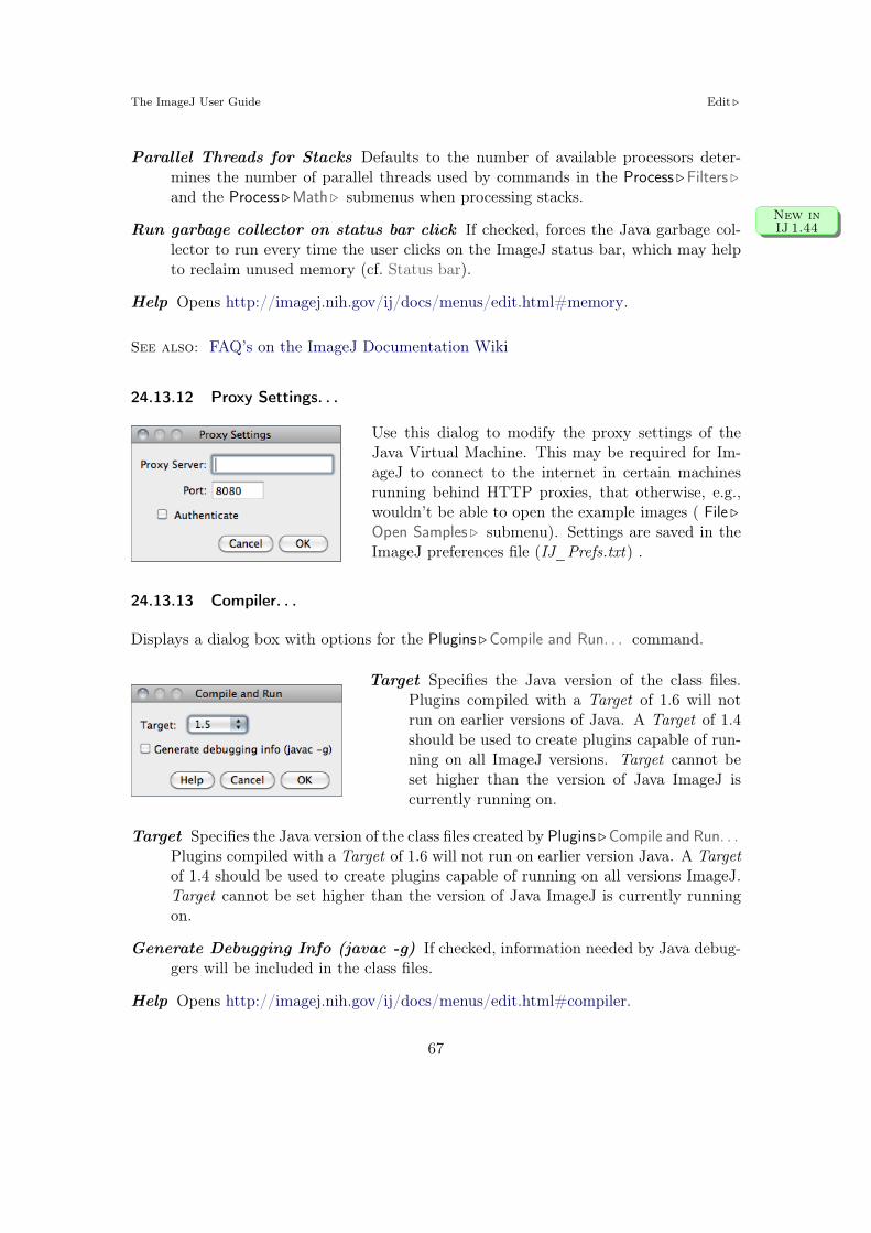
The ImageJ User Guide Edit !
Parallel Threads for Stacks Defaults to the number of available processors deter-mines the number of parallel threads used by commands in the Process !Filters !and the Process !Math ! submenus when processing stacks.
Run garbage collector on status bar click If checked, forces the Java garbage col-New inIJ 1.44
lector to run every time the user clicks on the ImageJ status bar, which may helpto reclaim unused memory (cf. Status bar).
Help Opens http://imagej.nih.gov/ij/docs/menus/edit.html#memory.
See also: FAQ’s on the ImageJ Documentation Wiki
24.13.12 Proxy Settings. . .
Use this dialog to modify the proxy settings of theJava Virtual Machine. This may be required for Im-ageJ to connect to the internet in certain machinesrunning behind HTTP proxies, that otherwise, e.g.,wouldn’t be able to open the example images ( File !Open Samples ! submenu). Settings are saved in theImageJ preferences file (IJ_Prefs.txt) .
24.13.13 Compiler. . .
Displays a dialog box with options for the Plugins !Compile and Run. . . command.
Target Specifies the Java version of the class files.Plugins compiled with a Target of 1.6 will notrun on earlier versions of Java. A Target of 1.4should be used to create plugins capable of run-ning on all ImageJ versions. Target cannot beset higher than the version of Java ImageJ iscurrently running on.
Target Specifies the Java version of the class files created by Plugins !Compile and Run. . .Plugins compiled with a Target of 1.6 will not run on earlier version Java. A Targetof 1.4 should be used to create plugins capable of running on all versions ImageJ.Target cannot be set higher than the version of Java ImageJ is currently runningon.
Generate Debugging Info (javac -g) If checked, information needed by Java debug-gers will be included in the class files.
Help Opens http://imagej.nih.gov/ij/docs/menus/edit.html#compiler.
67

The ImageJ User Guide Edit !
24.13.14 DICOM. . .Improvedin IJ 1.44
This dialog sets options related to the handling of DICOM im-ages. Namely, if ImageJ should open DICOM images as 32–bitfloat, if voxel depth should be calculated (based on the dis-tance between the first and last slices) and if coronal/transversesections should be mirrored when using the Image !Stacks !Orthogonal Views [H] command.
See also: Image Types and Image Formats
24.13.15 Misc. . .
Displays a dialog box containing miscellaneous op-tions.
Divide by zero value Specifies the value usedwhen Process ! Image Calculator. . . detectsa divide by zero while dividing one 32–bitreal image by another. The default is infin-ity. In addition to numeric values, ‘infinity’(positive or negative infinity), ‘max’ (largestpositive value) and ‘NaN’ (Not-a-Number)can be entered as the Divide by zero value.
Use pointer cursor If checked, ImageJ will use an arrow cursor instead of the defaultcross-hair that is sometimes di#cult to see on grayscale images in areas of mediumbrightness. This option can also be used to work around a bug on Windows wherethe text cursor is sometimes used in place of the cross-hair.
Hide "Process Stack?" dialog If checked, ImageJ will suppress the dialog that asks‘Process all xx slices?’ (only the current slice will be processed).
Require control / command key for shortcuts If checked, requires the Control key(Command key on Macs) to be pressed when using keyboard shortcuts for menucommands.
Move isolated plugins to Misc. menu This option can reduce the size of the Pluginsmenu, preventing it from running o" the bottom of the screen. When this optionis enabled, plugins that attempt install themselves in a submenu with only onecommand are instead installed in the Plugins !Miscellaneous submenu. An exampleof such a plugin is TurboReg, which normally creates a Plugins !TurboReg submenuthat contains only one command.
Run single instance listener If checked, ImageJ will use sockets to prevent multi-ple instances from being launched. On Windows, this avoids the problem where
68

The ImageJ User Guide Edit !
another copy of ImageJ starts each time an image is dragged and dropped on theImageJ icon. It also prevents multiple instances when running ImageJ from thecommand line. Note that you may get a security alert the first time ImageJ startswith this option enabled. ImageJ does not require external socket access so it isokay to deny it access in the security alert.
Debug mode If checked, causes ImageJ to display debugging messages in the ‘Log’window. Close the ‘Log’ window to disable display of debugging messages.
Help Opens http://imagej.nih.gov/ij/docs/menus/edit.html#misc.
69

The ImageJ User Guide Image !
25 Image !
25.1 Type !
Use this submenu to determine the type of the active image or to convert it to anothertype. An attempt to perform an unsupported conversion causes a dialog box to bedisplayed that lists the possible conversions.
Supported conversions in ImageJ (Image !Type ! submenu).
8–bit 16–bit 32–bit8–bitcolor
RGBcolor
RGBstack
HSBstack
8–bit . . . I, S I, S I, S
16–bit I, S . . . I, S I, S
32–bit I, S I, S . . . I, S
8–bit color I, S . . . I
RGB color I, S I, S . . . I, S I, S
RGB stack I . . .
HSB stack I . . .
I: Single images only; S: Stacks
8–bit Converts to 8–bit grayscale. ImageJ converts 16–bit and 32–bit images and stacksto 8–bits by linearly scaling from min–max to 0–255, where min and max are thetwo values displayed in the Image !Adjust !Brightness/Contrast. . . [C]. Image !ShowInfo. . . [i] displays these two values as Display range. Note that this scaling isnot done if Scale When Converting is not checked in Edit !Options !Conversions. . .RGB images are converted to grayscale using the formula gray = (red + green +blue)/3 or gray = 0.299 # red + 0.587 # green + 0.114 # blue if Weighted RGBConversions is checked in Edit !Options !Conversions. . .
16–bit Converts to unsigned 16–bit grayscale.
32–bit Converts to signed 32–bit floating-point grayscale.
8–bit Color Converts to 8–bit indexed color using Heckbert’s median-cut color quanti-zation algorithm. A dialog box allows the number of colors (2–256) to be specified.The active image must be RGB color.
RGB Color Converts to 32–bit RGB color.
RGB Stack Converts to a 3–slice (red, green, blue) stack. The active image must beRGB color.
70

The ImageJ User Guide Image !
HSB Stack Converts to a 3–slice (hue, saturation and brightness) stack. The activeimage must be RGB color.
25.2 Adjust !
This submenu contains commands that adjust brightness/contrast, threshold levels andimage size.
XI Applying Auto Brightness/Contrast to Entire Stacks
The Process !Enhance Contrast command can be used to adjust the brightness and contrast ofeach slice in a stack, according to either the optimal for each individual slice (if Use StackHistogram is unchecked) or the overall stack (if Use Stack Histogram is checked). The defaultbehavior of the B&C tool (Image !Adjust !Brightness/Contrast. . . [C]) is to use the overall stackhistogram.
XII Brightness/Contrast of High Bit–Depth Images
When displayed, the intensity of each pixel that is written in the image file is converted into thegrayness of that pixel on the screen. How these intensities are interpreted is specified by theimage type. From the ImageJ website:
16–bit and 32–bit grayscale images are not directly displayable on computer moni-tors, which typically can show only display 256 shades of gray. Therefore, the dataare mapped to 8–bit by windowing. The window defines the range of gray valuesthat are displayed: values below the window are made black, while values above thewindow are white. The window is defined by minimum and maximum values thatcan be modified using Image !Adjust !Brightness/Contrast. . . [C].
It may happen that the initial windowing performed by ImageJ on these high bit–depth (orHDR) images is suboptimal. Please note that windowing does not a!ect image data (cf. theHDRexplorerTool).
25.2.1 Brightness/Contrast. . . [C]Improvedin IJ 1.44
Use this tool to interactively alter the brightness and contrast of the active image. With8–bit images, brightness and contrast are changed by updating the image’s lookup table(LUT), so pixel values are unchanged. With 16–bit and 32–bit images, the display isupdated by changing the mapping from pixel values to 8–bit display values, so pixel
71

The ImageJ User Guide Image !
pixel values are also unchanged. Brightness and contrast of RGB images are changed bymodifying the pixel values.
Histogram The line graph at the top of the window, which is su-perimposed on the image’s histogram, shows how pixel valuesare mapped to 8–bit (0–255) display values. The two num-bers under the plot are the minimum and maximum displayedpixel values. These two values define the display range, or‘window’. ImageJ displays images by linearly mapping pixelvalues in the display range to display values in the range 0–255. Pixels with a value less than the minimum are displayedas black and those with a value greater than the maximumare displayed as white.
Minimum and Maximum sliders Control the lower and upperlimits of the display range. Holding down Shift will simulta-neously adjust all channels of a composite image (e.g., File !Open Samples !HeLa Cells (1.3 M, 48–bit RGB)).
Brightness slider Increases or decreases image brightness by moving the display range.Holding down Shift will simultaneously adjust all channels of a composite image.
Contrast slider Increases or decreases contrast by varying the width of the displayrange. The narrower the display range, the higher the contrast. Holding downShift will simultaneously adjust all channels of a composite image.
Auto ImageJ will automatically optimize brightness and contrast based on an analysisof the image’s histogram. Create a selection, and the entire image will be optimizedbased on an analysis of the selection. The optimization is done by allowing a smallpercentage of pixels in the image to become saturated (displayed as black or white).Each additional click on Auto increases the number of saturated pixels and thusthe amount of optimization. A run("Enhance Contrast", "saturated=0.35")macro call is generated if the command recorder is running.
Reset Restores the original brightness and contrast settings. The display range is setto the full pixel value range of the image. A resetMinAndMax() macro call isgenerated if the command recorder is running. Holding down Shift restores originalsettings in all channels of a composite image.
Set Allows to enter the minimum and maximum display range values in a dialog box.Improvedin IJ 1.44
A setMinAndMax() macro call is generated if the command recorder is running.Check Propagate to all open images to apply these values to the rest of theimages currently open.A 16–bit image consists of 65536 possible gray levels. Most of times, however, therelevant image information is contained only within a narrow range of the grayscale.This is the case, e.g., in low light microscopy, in which signal is restricted to the
72

The ImageJ User Guide Image !
lower end of the grayscale. The Set Display Range dialog allows you to choose howto scale the range of gray levels of 16–bit images.
Automatic Automatically selects the best range given the intensity values of theimage based on the percentage of the total number of pixel values from thelowest to highest pixel value.
8–bit (0–255) Gray level range of 0–255.10–bit (0–1023) Gray level range of 0–1023.12–bit (0–4095) Gray level range of 0–4095.15–bit (0–32767) Gray level range of 0–32767.16–bit (0-65535) Gray level range of 0–65535.
Apply Applies the current display range mapping function to the pixel data. If thereis a selection, only pixels within the selection are modified. This option currentlyonly works with 8–bit images and stacks and with RGB stacks. This is the onlyB&C option that alters the pixel data of non-RGB images.
See also: Window/Level. . . , Enhance Contrast, XI, XIII
25.2.2 Window/Level. . .
This command interactively adjusts theWindow – range of minimum and maxi-mum (Contrast) – and Level – position ofthat range in the grayscale intensity space(Brightness) – of the active image in a man-ner closer to that implemented on medicalimage terminals.
Being redundant with the Brightness/Con-trast. . . [C] tool, if the B&C window isopened, it will be closed and the W &L win-dow will be opened at the same location.
73

The ImageJ User Guide Image !
XIII Display Range of DICOM ImagesWith DICOM images, ImageJ sets the initial display range based on the Window Center(0028, 1050) and Window Width (0028, 1051) tags. Click Reset on the W&L (Image !Adjust !Window/Level. . . ) or B&C (Image !Adjust !Brightness/Contrast. . . [C]) window and the displayrange will be set to the minimum and maximum pixel values.
As an example, the File !Open Samples !CT (420K, 16–bit DICOM) image has a Window Centerof 50 and Window Width of 500, so the display range is set to -200 to 300 (center-width/2 tocenter+width/2). Click Reset and the display range is set to -719 to 1402. Press H (Analyze !Histogram [h]) and you will see that the minimum pixel value in the image is -719 and themaximum is 1402.
To display the DICOM tags, press I (Image ! Show Info. . . [i]). Press R (File !Revert [r]) torevert to the initial display range.
See also: Brightness/Contrast. . . [C]
25.2.3 Color Balance. . .
This panel makes adjustments to the brightnessand contrast of a single color of a standard RGBimage (8–bit per color channel). For multi-channelsstacks and hyperstacks it adjusts each of the colorchannels independently. Use the drop-down menuto specify which color / channel will be adjusted(the histogram is drawn for the selected color).
Maximum and Minimum sliders, Auto, Set andApply work as described for Image !Adjust !Brightness/Contrast. . . [C]. Similarly to the Win-dow/Level. . . tool, if the B&C window is opened, itwill be closed and the Color window will be openedat the same location.
NB: When switching from one color to another, thechanges made to one color will be lost unless Apply
is clicked before. Also, note that for 48–bit color images that load as a stack, Bright-ness/Contrast. . . [C] works on single stack slices, i.e., colors, and the color settings of theColor panel are ignored.
See also: Brightness/Contrast. . . [C], Color ! submenu
74

The ImageJ User Guide Image !
25.2.4 Threshold. . . [T] Improvedin IJ 1.44
Use this tool to automatically or interactively set lower and upper threshold values,segmenting grayscale images into features of interest and background. Use Analyze !Measure. . . [m]) (with Limit to Threshold in Analyze !Set Measurements. . . checked) tomeasure the aggregate of the selected features. Use Analyze !Analyze Particles. . . tomeasure features individually. Use the Wand Tool to outline a single feature.
Are objects in the image lighter than the background?!
Thresholding methods! Highlighted range!
Min/Max values!
Display mode!
Manual input!
Holding moves a fixed-width thresholding window !
Shift ⇪
Image !Adjust !Threshold. . . [T] (ImageJ 1.43m).
Upper slider Adjusts the minimum threshold value. Hold Shift while adjusting theminimum to move a fixed-width thresholding window across the range of grayvalues.
Lower slider Adjusts the maximum threshold value.
Method Allows any of the 16 di"erent automatic thresholding methods to be selected[12]. These methods are described on Fiji’s Auto Threshold website (http://pacific.mpi-cbg.de/wiki/index.php/Auto_Threshold). The Default method is the modi-fied IsoData method used by ImageJ 1.41 and earlier.
Display Selects one of three display modes:
Red Displays the thresholded values in red.
B&W Features are displayed in black and background in white. Thismode respects the Black background flag set in Process !Binary !Options. . .
75

The ImageJ User Guide Image !
Over/Under Displays pixels below the lower threshold value in blue, thresh-olded pixels in grayscale, and pixels above the upper thresholdvalue in green. These colors can be changed from a macro by call-ing the ImageProcessor.setOverColor() and setUnderColor()methods (example).
Dark background To be checked when features are lighter than the background. WithNew inIJ 1.44
IJ 1.44i and later, the state of the checkbox is remembered across restarts.
Auto Uses the currently selected thresholding method to automatically set the thresholdlevels based on an analysis of the histogram of the current image or selection.
Apply Sets thresholded pixels to black and all other pixels to white. For 32–bit floatimages Apply will also run Process !Math !NaN Background.
Reset Disables thresholding and updates the histogram.
Set New threshold levels can be entered into this dialog box.
See also: XVII
25.2.5 Color Threshold. . .Improvedin IJ 1.44
Thresholds 24–bit RGB images based on Hue Saturation and Brightness (HSB), RedGreen and Blue (RGB), CIE Lab or YUV components. Ranges of the filters can be setmanually or based on the pixel value components of a user-defined ROI (experimental).This command, implemented in version 1.43l, is a built-in version of the Threshold Colourplugin [14]. Note that the final thresholded image type is RGB, not 8–bit gray.
76

The ImageJ User Guide Image !
Segmentation of DAPI stained nuclei using Image !Adjust !Color Threshold. . .
Pass If checked, values within range are thresholded and displayed (band-pass filter),otherwise, values outside the selected range are thresholded (band-reject filter).
Thresholding Method Allows any of the 16 di"erent automatic thresholding methodsNew inIJ 1.44
to be selected (cf. Threshold. . . [T]).
Threshold Color Selects the threshold color: either Red, Black, White or Black &White (cf. Threshold. . . [T]).
Color space Selects the color space: HSB, RGB, CIE Lab or YUV.
Dark background To be checked when features are lighter than the background. WithNew inIJ 1.44
IJ 1.44i and later, the state of the checkbox is remembered across restarts.
Original Restores the original image and updates the bu"er when switching to anotherimage.
Filtered Shows the filtered image.
Select Creates a ROI selection based on the current settings. The selection is madeaccording to the settings defined in the Process !Binary !Options. . . dialog.
Sample (Experimental) Sets the ranges of the filters based on the pixel value compo-nents in a user-defined ROI.
Stack Processes the rest of the slices in a stack (if any) using the current settings.
77

The ImageJ User Guide Image !
Macro Creates a macro based on the current settings which is sent to the MacroRecorder window (Plugins !Macros !Record. . . ) , if open.
Help Opens Color Threshold. . . ’s built-in help.
See also: 3D Color Inspector/Color Histogram
25.2.6 Size. . .Improvedin IJ 1.44
Scales the active image or selection to aspecified Width and Height in pixels.
Check Constrain aspect ratio and Im-ageJ will adjust either the Height or theWidth to maintain the original aspect ra-tio. When applicable, other dimensionscan also be resized: Depth (images) instacks, Depth (slices) and Time (frames)in hyperstacks.
Check the Average when downsizing check-box for better results when scaling downimages [13].
Two resampling methods are possible: Bilinear and Bicubic interpolation. The imple-mentation of the bicubic method (Catmull-Rom interpolation) is derived from Burgerand Burge, 2009 [47].
See also: Image ! Scale. . . [E]
25.2.7 Canvas Size. . .
Changes the canvas size of an image or stackwithout scaling the actual image. Width andHeight may be either expanded or contracted.If the canvas size is increased, the border is filledwith the current background color, or, if Zero Fillis checked, the border is filled with pixels thathave a value of zero. The position of the old im-age within the new canvas may also be specified.
See also: Size. . . , Color Picker. . . [K], XIV
78

The ImageJ User Guide Image !
25.2.8 Line Width. . .
This widget is used to adjust the width of lineselections. It is opened more easily by dou-ble clicking on the Line Selection Tools icon.Checking Spline Fit fits a cubic spline curveto the points that define the line.
See also: Edit !Options ! Line Width. . . , Edit ! Selection !Fit Spline
25.3 Show Info. . . [i]Improvedin IJ 1.44
Opens a text window containing informationabout the active image (including the pixel orvoxel size, since IJ 1.44k). For DICOM andFITS images, also displays file header informa-tion. Use the popup menu (right-click in theInfo window) to save the information to a textfile or copy it to the system clipboard.
See also: Image !Properties. . . [P]
25.4 Properties. . . [P]
Use this command to display and set various properties ofthe current image or stack.
The number of Channels (c), Slices (z) and Frames (t) inthe image can be changed as long as the product of c, z, andt is equal to the number of images in the stack.
The Unit of Length (a string describing the measuring unit),Pixel Width, Pixel Height and Voxel Depth (all in the Unitof Length unit) can be set.
Width, Height and Depth are automatically converted if Unitof Length is changed from one known unit (‘nm’, ‘um’, ‘µm’,‘micron’, ‘mm’, ‘cm’, ‘meter’, ‘km’ or ‘inch’) to another.
With t–series stacks, the Frame Interval in seconds (reciprocal of the frame rate) canbe viewed and set. Since IJ 1.43, setting the Frame Interval sets the frame rate used byAnimation Options. . . [Alt /] as long as the unit used is ‘sec’.
79

The ImageJ User Guide Image !
Origin (always in pixels) is the reference point (0, 0) of the image coordinate system (seealso Analyze ! Set Measurements. . . ).
Check Global to make the current settings global (i.e., apply to all images opened duringthe current session, cf. XVIII).
See also: Image ! Show Info. . . [i], Image ! Scale. . . [E], Analyze !Set Scale. . .
25.5 Color !
This submenu contains commands that deal with color images.
25.5.1 Split Channels
Splits an RGB image (or stack) into three 8–bit grayscale images containing the red, greenand blue components of the original. The window names have an appended (red), (green)and (blue). With composite images and / or hyperstacks (e.g., File !Open Samples !Organof Corti (2.8M, 4D stack)) this command splits the stack into separate channels.
See also: Merge Channels. . .
25.5.2 Merge Channels. . .Improvedin IJ 1.44
Merges 1–4 grayscale images or stacks into an RGB image orstack. Select *None* to keep a channel empty (filled with 0).
Check Keep Source Images if you wish to keep the originals.Check Create Composite to convert 2–4 grayscale images orstacks into a composite image or hyperstack (see Color Com-posites). With IJ 1.44n and later, LUTs and display rangesare preserved if Create Composite is chosen.
See also: Channels. . . [Z]
25.5.3 Channels Tool. . . [Z]
Alias for Image !Hyperstacks !Channels. . . [Z].
25.5.4 Stack to RGB
Converts a two or three slice stack into an RGB image, assuming that the slices are inR, G, B order. The stack must be 8–bit or 16–bit grayscale. Also converts compositeimages (e.g., File !Open Samples !HeLa Cells (1.3M, 48-bit RGB)) into RGB.
80

The ImageJ User Guide Image !
25.5.5 Make Composite Improvedin IJ 1.44
Converts in place an RGB image, a 2–7 image stack ora 2–7 channel hyperstack into a composite color image.Use the Channels. . . [Z] tool ( Shift Z ) to enable anddisable the channels of a composite image. Use Bright-ness/Contrast. . . [C] ( Shift C ) to adjust the brightnessand contrast of the current channel.
25.5.6 Show LUT
Displays a plot of the active image’s lookup ta-ble (LUT) . The lookup table, or color table,describes the color that is displayed for each ofthe 256 possible pixel values. For 16 and 32–bit images, the range of displayed pixel values ismapped to 0–255. A bar under the plot displaysthe color representation of the pixel values. Notethat RGB color images do not use a lookup ta-ble. Use the List. . . radio button to export theLUT as a CSV file.
See also: Edit LUT. . .
25.5.7 Edit LUT. . .
Opens the ImageJ LUT (Lookup Table) Editor.A lookup table in ImageJ has up to 256 entries.The entry index, and the three values (red, greenand blue) associated with it, are displayed in theImageJ status bar as you move the cursor over theLUT Editor window. Click on an entry to edit thered, green and blue values for that entry using aColor Selector window (cf. Color Picker. . . [K]).
See also: Show LUT
25.5.8 Color Picker. . . [K]
The Color Picker tool [11] enables the user to select foreground and background colors,which a"ect Edit !Fill [f], Edit !Draw [d] and other color drawing commands. It displayscurrent foreground and background colors in the selection boxes at the bottom of thewindow. It has two modes: Foreground and Background. To change modes, click on the
81

The ImageJ User Guide Image !
desired selection box. Clicking on the Foreground/Background Switcher button sets thecurrent foreground to the background and vice versa. The Black/White Reset buttonsets the foreground to black and the background to white.
Black– White Ramp!
Foreground Color!
Background Color!
Red!
Yellow!
Green!
Blue!
Cyan!
Magenta!
Foreground/Background Switcher!
Black/White Reset!
Color Selectors!
Color Ramp !Algorithm!
◀B S▶!H!
▼!
The Color Picker. . . [K] tool.
The color palette is based on HSB (Hue, Saturation and Brightness) color model. Hueincreases as you go down the palette while saturation and brightness values are splithorizontally. The left half of the palette varies only in brightness while the right halfvaries only in saturation. At the center of the color ramp are enlarged red, green, blue,cyan, magenta, and yellow colors for quick selection. To the left of the color palette is agrayscale ramp that goes from pure black to pure white.Double clicking on a color brings up one of the Color Selectors, shown on the right in theillustration. Use the sliders to specify the RGB values of the foreground or backgroundcolor. To get precise colors, manually change the values in the text boxes. The title ofthe Color Selector window (Foreground Color or Background Color) indicates the currentselection mode.
See also: XIV, Draw [d], Fill [f], Clear, Clear Outside, Image Types and Image Formats
25.6 Stacks !
This submenu contains commands that work with stacks.
25.6.1 Add Slice
Inserts a blank slice after the currently displayed slice. Holding Alt inserts a blank slicebefore the current slice.
82

The ImageJ User Guide Image !
XIV Embedding Color Annotations in Grayscale ImagesColor marks are only available with color images or grayscale images that have been convertedto RGB. For non-RGB images, background / foreground color will be painted in equivalent graylevels, e.g.: In a 8–bit image, if the foreground color is red (RGB: 255, 0, 0) intensity of drawnselections will be (255 + 0 + 0)/3 = 85. Although this issue can be overcome by convertingthe image into RGB (Image !Type ! submenu), the easiest way to embed true color selections ingrayscale images is to use the Image !Overlay !Add Selection. . . [b] command followed by Image !Overlay !Flatten [F].
25.6.2 Delete Slice
Deletes the currently displayed slice.
25.6.3 Next Slice [>]
Displays the slice that follows the currently displayed slice. Holding Alt > will skipnine slices forward.
See also: Arrow Keys
25.6.4 Previous Slice [<]
Displays the slice that precedes the currently displayed slice. Holding Alt < will skipnine slices backward.
See also: Arrow Keys
25.6.5 Set Slice. . .
Displays a specified slice. The user must enter a slice num-ber greater than or equal to one and less than or equal tothe number of slices in the stack.
25.6.6 Images To StackImprovedin IJ 1.44
Creates a new stack from images currently displayed in separate windows.
83

The ImageJ User Guide Image !
Method If images di"er in size, a drop-down menu allows to choose a conversion method:
Copy (center / top-left) Stack will have the width of the widest open imageand the height of the highest open image. Smaller images will then be copied(either to the center or to the upper left corner) of the slice. Borders are filledwith pixels that have a value of zero.
Scale (smallest / largest) Stack will have the dimensions of the smallest / largestopen image. Other images are scaled to the new slice dimensions. Bicubic in-terpolation is used if Bicubic interpolation is checked (cf. Image !Size. . . andImage !Scale. . . [E]).
Name Specifies the title of the stack to be created.
Title Contains Enter a string intothis field and ImageJ will onlyconvert to stack images whosename contains that string.
Bicubic Interpolation If checked,bicubic interpolation (cf. Adjust !Size. . . ) will be used if any ofthe Scale methods was previouslychosen.
Use Title as Labels If checked, im-age titles (without extension) willbe used as stack labels.
Keep Source Images If checked,original images are kept.
25.6.7 Stack To Images
Converts the slices in the current stack to separate image windows.
25.6.8 Make Montage
Produces a single image which contains the images from a stack displayed in a gridformat. This can be useful for visual comparisons of a series of images stored in a stackand to create ‘panel figures’. With hyperstacks – that are not directly supported –,instructions are displayed that explain how to create c, z or t montages. A dialog boxallows you to specify the magnification level at which the images are copied, and to selectthe layout of the resulting grid.
84

The ImageJ User Guide Image !
Label Slices If checked, images are be labeled in the panel. If no slice metadata exists(the setMetadata("Label", string) macro function can be used to customizeslice labels) images are labeled with slice numbers. Note that the Label. . . com-mand can also be used to draw labels in stack slices.
Use Foreground Color If checked, borders and labels are drawn in the foregroundcolor and blank areas of the panel are filled with the background color.
See also: Stacks !Tools !Montage to Stack. . . command, RC Montage plugin, MagicMontage — a macro toolset to reorder and manipulate images in the montage(a video tutorial can be found here)
25.6.9 Reslice. . . [/]
Reconstructs one or more orthogonal slices throughthe image volume represented by the current stackor hyperstack [15].
The estimated size of the output stack and theamount of available memory are displayed at thebottom of the dialog. Increase Output spacing toreduce the size of the output stack.
A dialog allows you to specify the spacing of thereconstructed slices.
Output spacing Determines the number of orthogonal slices that will be reconstructed.Increasing Output spacing reduces the size of the output stack.
85

The ImageJ User Guide Image !
Start at Determines the image edge (top, left, bottom or right) from which reconstruc-tion starts. Start at is replaced by Slice count if there is a line selection. With linesselections, a stack is created by shifting (by Output spacing) the line down and tothe left to generate additional slices for the output stack. In this case, the size ofthe output stack in determined by Slice count.
Flip vertically If checked, each slice in the output stack will be flipped vertically.
Rotate 90 degrees If checked, each slice in the output stack will be rotated 90".
Avoid interpolation If checked, no interpolation will be done.
Help Opens http://imagej.nih.gov/ij/docs/menus/image.html#reslice.
See also: Dynamic Reslice and Radial Reslice plugins
25.6.10 Orthogonal Views [H]Improvedin IJ 1.44
Provides an orthogonal view display of thecurrent stack or hyperstack [16]. E.g., if astack displays sagittal sections, coronal (YZprojection image) and transverse (XZ pro-jection image) will be displayed through thedata-set.
The two extra planar views are displayed in‘sticky’ panels next to original image and canbe toggled using Shift H , the commandshortcut.
The intersection point of the three views fol-lows the location of the mouse click and canbe controlled by clicking and dragging in ei-ther the XY, XZ or YZ view. XY and XZcoordinates are displayed in the title of theprojection panels. The mouse wheel changesthe screen plane in all three views.
Voxel dimensions can be adjusted in Image !Properties. . . [P].
See also: 3D Project. . . , and 3D Viewer [9], Volume Viewer, Stack Slicer Display3_TPplugins, Edit !Options !DICOM. . .
86

The ImageJ User Guide Image !
25.6.11 Z Project. . .Improvedin IJ 1.44
Projects an image stack along the axis perpendicular to image plane (the so-called zaxis) [15]. Five di"erent projection types are supported. With ImageJ 1.44l and later,the preferred projection method is stored in the preferences file.
Average Intensity projection outputs an image wherein each pixel stores average in-tensity over all images in stack at corresponding pixel location.
Average Intensity projection outputs animage wherein each pixel stores aver-age intensity over all images in stackat corresponding pixel location.
Maximum Intensity projection (MIP)creates an output image each ofwhose pixels contains the maximumvalue over all images in the stack atthe particular pixel location.
Sum Slices projection creates a real image that is the sum of the slices in the stack.
Standard Deviation projection creates a real image containing the standard deviationof the slices.
Median projection outputs an image wherein each pixel stores median intensity overall images in stack at corresponding pixel location.
See also: Grouped Z Project. . . , 3D Project. . . , Plot Z-axis Profile. . .
87

The ImageJ User Guide Image !
25.6.12 3D Project. . .Improvedin IJ 1.44
This command creates a sequence of projectionsof a rotating volume (stack or hyperstack) ontoa plane using nearest-point (surface), brightest-point, or mean-value projection or a weightedcombination of nearest point projection with ei-ther of the other two methods (partial opacity)[17]. The user may choose to rotate the volumeabout any of the three orthogonal axes (x, y, orz), make portions of the volume transparent (us-ing thresholding), or add a greater degree of vi-sual realism by employing depth cues.
Each frame in the animation sequence is the re-sult of projecting from a di"erent viewing angle.To visualize this, imagine a field of parallel rayspassing through a volume containing one or moresolid objects and striking a screen oriented nor-mal to the directions of the rays.
Each ray projects a value onto the screen, or projection plane, based on the valuesof points along its path. Three methods are available for calculating the projectionsonto this plane: nearest-point, brightest-point, and mean-value. The choice of projectionmethod and the settings of various visualization parameters determine how both surfaceand interior structures will appear.
Projection Method Select Nearest Point projection to produce an image of the sur-faces visible from the current viewing angle. At each point in the projection plane,a ray passes normal to the plane through the volume. The value of the nearestnon transparent point which the ray encounters is stored in the projection image.Brightest Point projection examines points along the rays, projecting the brightestpoint encountered along each ray. This will display the brightest objects, such asbone in a CT (computed tomographic) study. Mean Value projection, a modifica-tion of brightest–point projection, sums the values of all transparent points alongeach ray and projects their mean value. It produces images with softer edges andlower contrast, but can be useful when attempting to visualize objects containedwithin a structure of greater brightness (e.g. a skull).
Slice Spacing The interval, in pixels, between the slices that make up the volume. Im-ageJ projects the volume onto the viewing plane at each Rotation Angle Increment,beginning with the volume rotated by Initial Angle and ending once the volumehas been rotated by Total Rotation.
Lower /Upper Transparency Bound Determine the transparency of structures inthe volume. Projection calculations disregard points having values less than the
88

The ImageJ User Guide Image !
lower threshold or greater than the upper threshold. Setting these thresholds per-mits making background points (those not belonging to any structure) invisible.By setting appropriate thresholds, you can strip away layers having reasonably uni-form and unique intensity values and highlight (or make invisible) inner structures.Note that you can also use Image !Adjust !Threshold. . . [T] to set the transparencybounds.
Opacity Can be used to reveal hidden spatial relationships, specially on overlappingobjects of di"erent colors and dimensions. The (surface) Opacity parameter permitsthe display of weighted combinations of nearest-point projection with either of theother two methods, often giving the observer the ability to view inner structuresthrough translucent outer surfaces. To enable this feature, set Opacity to a valuegreater than zero and select either Mean Value or Brightest Point projection.
Surface / Interior Depth–Cueing Depth cues can contribute to the three-dimensionalquality of projection images by giving perspective to projected structures. Thedepth-cueing parameters determine whether projected points originating near theviewer appear brighter, while points further away are dimmed linearly with dis-tance. The trade-o" for this increased realism is that data points shown in adepth-cued image no longer possess accurate densitometric values. Two kinds ofdepth-cueing are available: Surface Depth-Cueing and Interior Depth-Cueing. Sur-face Depth-Cueing works only on nearest-point projections and the nearest-pointcomponent of other projections with opacity turned on. Interior Depth-Cueingworks only on brightest-point projections. For both kinds, depth-cueing is turnedo" when set to zero (i.e. 100% of intensity in back to 100% of intensity in front) andis on when set at 0 <n 100 (i.e. (100"n)% of intensity in back to 100% intensityin front). Having independent depth-cueing for surface (nearest-point) and interior(brightest-point) allows for more visualization possibilities.
Interpolate Check Interpolate to generate a temporary z-scaled stack that is used togenerate the projections. Z-scaling eliminates the gaps seen in projections of vol-umes with slice spacing greater than 1.0 pixels. This option is equivalent to usingthe Scale plugin from the TransformJ package to scale the stack in the z-dimensionby the slice spacing (in pixels). This checkbox is ignored if the slice spacing is lessthan or equal to 1.0 pixels.
See also: Orthogonal Views [H], Z Project. . . , Grouped Z Project. . . and 3D Viewer [9],Volume Viewer plugins
89

The ImageJ User Guide Image !
25.6.13 Plot Z-axis Profile. . .
Plots the ROI selection mean gray valueversus slice number. Requires a point orarea selection.
Coordinates of the upper left corner of theselection (or the bounding rectangle fornon-rectangular selections) are displayed inthe graph title.
See also: Profile Plot Options. . . , Plot Pro-file [k]
25.6.14 Label. . .Improvedin IJ 1.44
Adds a sequence of numbers (e.g., timestamps) and/ora label to a stack or hyperstack. Numbers and labelare drawn in the current foreground color (cf. Image !Colors !Color Picker. . . [K]).
The initial X,Y location, and Font size of the label arebased on the existing rectangular selection, if any. Slicesoutside the Range are not a"ected.
Format Specifies the structure of the label. 0 : Un-padded sequence; 0000 : Pads each number withleading zero(s); 00 : 00 : Converts the label into aminutes : seconds timestamp; 00 : 00 : 00 Convertsthe label into a hours :minutes : seconds times-tamp; Text : Stamps only the contents of the Textfield.
Starting value and Interval Specify the first value and the numeric steps to be ap-plied. Note that with timestamps, metric time values must be used, e.g., an Intervalof 3600 will create 1 hour increments.
Text The string to be drawn after each number when the Format chosen is either 0 orText (label without numeric sequence).
Use overlay If checked, labels will be created as non-destructive image overlays. NoteNew inIJ 1.44
that previously added overlays will be removed.
Help Opens http://imagej.nih.gov/ij/docs/menus/image.html#label.
See also: Make Montage, Stacks !Tools ! Insert. . .
90

The ImageJ User Guide Image !
25.6.15 Tools !
25.6.15.1 Combine. . .
Combines two stacks [Width#Height#Depth](W1#H1#D1 and W2#H2#D2) to create a newW1+W2#max(H1,H2)#max(D1,D2) stack. E.g., a256#256#40 and a 256#256#30 stack would be com-bined to create one 512#256#40 stack.
If Combine vertically is enabled, creates a newmax(W1+W2)#(H1+H2)#max(D1,D2) stack.
Unused areas in the combined stack are filled with back-ground color (cf. Color Picker. . . [K]).
See also: Concatenate. . .
25.6.15.2 Concatenate. . .
Concatenates two images or stacks that have the samewidth, height and data type.
See also: Combine. . .
25.6.15.3 Reduce. . .
Reduces the size of stacks and hyperstacks by the specifiedReduction Factor. E.g., For a 30 slices stack and a Reduc-tion Factor of 2, the reduced stack will be be composedof 15 slices with every second slice being removed. Virtualstacks/hyperstacks are supported
With Hyperstacks, the default reduction is performed inthe T-Dimension, but a choice is available to Reduce in Z-Dimension instead.
See also: Hyperstacks !Reduce Dimensionality. . .
25.6.15.4 Reverse
Alias for the Image !Transform !Flip Z command.
91

The ImageJ User Guide Image !
25.6.15.5 Insert. . .
Inserts an image or stack into a stack atthe specified X and Y Location. TheSource Image or Stack must be of thesame type as the Destination Stack.
See also: Image !Stacks ! Label. . .
25.6.15.6 Montage to Stack. . .Improvedin IJ 1.44
Converts a montage image to an image stack based on thespecified number of rows and columns, taking into accounta Border width. This is the opposite of what the Image !Stacks !Make Montage command does.
See also: Demontager plugin
25.6.15.7 Make Substack. . .New inIJ 1.44
Extracts selected images from the activestack copying them to a new stack in theorder of listing or ranging [18].
It takes one of three types of input: 1) Arange of images (e.g. 2–14); 2) A range ofimages with increment (e.g. 2–14–2) or 3)a list of images (e.g. 2, 4, 7 ,9, 14).
Currently, it does not work with hyperstacks.
See also: Image !Duplicate. . . [D]
25.6.15.8 Grouped Z Project. . .New inIJ 1.44
Creates a substack of Stack size/Group sizeslices with each slice being the result of a ZProjection performed over the range of Groupsize. Note that Group size must divide evenlyinto the stack size.
See also: Image ! Stacks !Z Project. . .
92

The ImageJ User Guide Image !
25.6.15.9 Start Animation [\]
Animates the active stack by repeatedly displaying its slices (frames) in sequence. It isrun more easily by clicking on the play icon preceding stack sliders (see Stacks). To stopthe animation, click on the slider pause icon, click on the image or use Stop Animation[\], evoked by the same shortcut. As such, stacks animation can be toggled using \. The frame rate is displayed in the status bar. Open the Animation Options. . . [Alt /]dialog box to specify the animation speed (pressing Alt \ or right-clicking on the onthe slider play/pause icon opens the Animation Options. . . dialog). Note that more thanone stack can be animated at a time.
25.6.15.10 Stop Animation [\]
Terminates animation of the active stack (see Start Animation [\]).
25.6.15.11 Animation Options. . . [Alt /]
Use this dialog to set the animation speed in frames persecond, the starting and ending frame, or to enable ‘oscil-lating’ animations. Selecting Start Animation animates thestack as soon as the dialog is dismissed.
Note that with IJ .43 and later, setting the Frame Intervalin Image !Properties. . . [P] sets the animation speed as longas the unit used is ‘sec’.
This dialog can also be accessed by right-clicking on the play/pause icon that precedesstack sliders and hyperstack slice sliders (see Stacks).
See also: File ! Save As !Gif. . . , AVI. . .
25.7 Hyperstacks !
This submenu contains commands that work with hyperstacks, images that have four(4D) or five (5D) dimensions (see Stacks).
93

The ImageJ User Guide Image !
25.7.1 New Hyperstack. . .
Creates a new hyperstack. Hyperstacks have Width,Height, Channels (c dimension), Slices (z dimension)and time Frames (t dimension).
Image Type (see Image !Type ! ) and Display Mode(see Channels. . . [Z]) can be specified.
Checking Label Images will draw the channel num-ber, slice number and frame number on each imagein the hyperstack.File !New !Hyperstack. . . is an alias of this command.
See also: Hyperstacks
25.7.2 Stack to Hyperstack. . .
Converts a stack into a hyperstack. RGB stacksare converted into 3 channel hyperstacks.
Order is the order of the channels (c), slices (z )and frames (t) within the stack. ImageJ hyper-stacks are always in czt order. Stacks not in cztorder will be shu!ed to be in czt order. Thechannel Display Mode can be Composite, Coloror Grayscale (cf. Channels. . . [Z]).
See also: Hyperstack to Stack
25.7.3 Hyperstack to Stack
Converts a hyperstack into a stack (in czt order).
See also: Stack to Hyperstack. . .
94

The ImageJ User Guide Image !
25.7.4 Reduce Dimensionality. . .
[19] This command reduces the dimensionality of an hyperstackby creating a new hyperstack with, for example, all the channelsand time points at a given z position or all the z slices for thecurrent channel and time point.
Uncheck Channels (n) to delete all but the current channel,Slices (n) to delete all but the current z slice and Frames (n)to delete all but the current time point. Check Keep Source andthe original stack will not be deleted.
The expected dimensions and size of the reduced stack are displayed in the dialog.
See also: Hyperstack to Stack
25.7.5 Channels. . . [Z]
Opens the ‘Channels’ window, or brings it to the front if it is already open. ShiftZ is the keyboard shortcut for this command. This tool allows to select the Displaymode of composite images. In addition, several commands hosted in the Image !Color !submenu can easily be accessed through the More# drop-down menu. The same drop-
down menu also provides a convenient list of primary colors (additive: red, green andblue, subtractive: cyan, magenta, yellow) that can be used to pseudocolor compositechannels. Composite images are discussed with more detail in Color Composites.
25.8 Crop [X]
Crops the image or stack based on the current rectangular selection.
95

The ImageJ User Guide Image !
25.9 Duplicate. . . [D]New inIJ 1.44
Creates a new window containing a copy of the active imageor rectangular selection. For stacks and hyperstacks it ispossible to specify the range of Channels (c), Slices (z) andFrames (t) to be duplicated.
With single images, hold Alt to skip the dialog box.
25.10 Rename. . .
Renames the active image.
25.11 Scale. . . [E]Improvedin IJ 1.44
Resizes the image or current area selection by scalefactors entered into a dialog box. As with Image !Size. . . , two resampling methods are possible: Bilinearand Bicubic interpolation.
For the best looking results, particularly with graphicsand text, use integer scale factors (2, 3, 5, etc.) andcheck Average when downsizing with scale factors lessthan 1.0 [13]. Also, when downsizing, smoothing thesource image prior to scaling may produce better look-ing results.
Scaled image/selection are copied to a new imagenamed Title if Create new window is checked. If scalinga selection that will not be copied to a new image checkFill with Background Color to fill with the backgroundcolor instead of zero.
Entire stacks (or hyperstacks in the Z Dimension) willbe scaled if Process entire stack is checked.
96

The ImageJ User Guide Image !
25.12 Transform !
This submenu contains commands that perform geometrical image transformation on theactive image or stack.
25.12.1 Flip Horizontally
Replaces the image or selection with a x-mirror image of the original.
25.12.2 Flip Vertically
Turns the image or selection upside down (y-mirror).
25.12.3 Flip Z
Reverses the order of the slices in a stack (z-mirror).
25.12.4 Rotate 90 Degrees Right
Rotates the entire image or stack clockwise 90".
25.12.5 Rotate 90 Degrees Left
Rotates the entire image or stack counter-clockwise 90".
25.12.6 Rotate. . . see
Use this dialog to rotate the ac-tive image or selection clockwisethe specified number of degrees.
Set Grid Lines to a value greaterthan zero to superimpose agrid on the image in Previewmode. Two resampling meth-ods are possible: Bilinear andBicubic interpolation (cf. Im-age !Size. . . ).
With 8–bit and RGB images, check Fill with Background Color to fill with the back-ground color instead of zero (cf. Color Picker. . . [K]). Check Enlarge to Fit Result andthe image will be enlarged as needed to avoid clipping.
97

The ImageJ User Guide Image !
25.12.7 Translate. . .
Translates (moves) the image in the x and y directionsby a specified number of pixels. With stacks, you cantranslate either the current image or all the images in thestack. Two resampling methods are possible: Bilinearand Bicubic interpolation (cf. Image !Size. . . ).
Check Preview to see how the translation will a"ect theimage. The background at the edges of the image will beset to 0.
See also: Align_Slice and Align_RGB_planes plugins
25.13 Zoom !
This submenu contains commands that control how the current image is displayed. The+ and ! or " and # keys are the preferred way to use the In and Out commands.When a selection exists, zooming with the arrow keys requires holding down either Shiftor Ctrl .
25.13.1 In [+]Improvedin IJ 1.44
Zooms in to next higher magnification level and, if possible, enlarges the window. Thereare 21 possible levels (shown in the title bar): 3.1, 4.2, 6.3, 8.3, 12.5, 16.7, 25, 33.3, 50,75, 100, 150, 200, 300, 400, 600, 800, 1200, 1600, 2400 and 3200 %.
XV Scrolling Zoomed ImagesHold down the space bar and drag to scroll a zoomed image.
25.13.2 Out ["]Improvedin IJ 1.44
Zooms out to next lower magnification level and, if needed, shrinks the window.
25.13.3 Original Scale [4]
Displays the image at the magnification used when the image was first opened. As ashortcut, double click on the magnifying glass tool.
98

The ImageJ User Guide Image !
25.13.4 View 100% [5]
Displays the image using 100% magnification (1 image pixel = 1 screen pixel). EnableOpen Images at 100% in the Edit !Options !Appearance. . . dialog to have images auto-matically opened at 100% magnification.
25.13.5 To Selection
Zooms in based on the current selection. Note that in the absence of a selection, thiscommand zooms the image to a ‘Fit to Screen’ level.
25.13.6 Set. . .
Sets an exact zoom to any open image beyond predefined zoom levels, e.g. 37.4% [20].
25.14 Overlay !
This submenu contains commands for creating and working with non-destructive imageoverlays. An overlay consists of one or more selections (arrows, lines, points, shapes andtext). Press B (Add Selection. . . [b]) to add the current selection to the overlay. PressShift F (Flatten [F]) to create an RGB image with the overlay embedded in it. Theoverlay is preserved when an image is saved in TIFF format (cf. II).
Non-destructive image overlays. Outputs from Grid_Overlay, MakeOverlay and ROI ColorCoder, macros that exemplify the usage of most Image !Overlay ! submenu commands.
99

The ImageJ User Guide Image !
25.14.1 Add Selection. . . [b]Improvedin IJ 1.44
Adds the current selection to the overlay, displaying the dialogbox depicted on the left. Stroke Color, Stroke Width and FillColor to be set. Except for text selections, the stroke (line)color and width are ignored if a fill color is specified.
Hold Alt to skip the Add to Overlay dialog.
Colors are specified using the name of one of the eight de-fault colors (black, blue, cyan, green, magenta, red, white andyellow) or using hex notation.
Hex color codes must be given as either a 6–digit hexadecimal number in the form#RRGGBB (opaque colors), or a 8–digit number in the form #AARRGGBB where AAspecifies the alpha blending value, RR the intensity of red, GG the intensity of green andBB the intensity of blue. The table below provides the conversion of some RGB colortriplets into hex notation.
Previously added overlays are removed if New Overlay is checked.
See also: Selection !Properties. . . [y], ROI Manager. . . , XVI, ROI Color Coder and RG-BtoHEX macros
XVI Working With HEX Colors
Hexadecimal notation (hex) is frequently used in computing because it can summarize binarycode in a human-friendly manner. For example, RGB colors that typically range from 0 to 255can be succinctly represented as two hexadecimal digits (ranging from 00 through FF). ImageJ’sbuilt-in macro function toHex() returns hexadecimal representations of decimal numbers andcan be used to convert RGB color values into hex color notation (see RGBtoHEX macro).
The following table exemplifies some decimal / hexadecimal equivalents:
Dec 0 1 2 3 4 5 6 7 8 9 10 11 12 13 14 15 16 17 18 19 20 . . . 30 40 50 60 70 80 90 . . . 100 . . . 255Hex 0 1 2 3 4 5 6 7 8 9 A B C D E F 10 11 12 13 14 . . . 1E 28 32 3C 46 50 5A . . . 64 . . . FF
100

The ImageJ User Guide Image !
Hexadecimal notation of RGB colors. As with RGB triplets, alpha values range from 0 (fullytransparent) to 255 (solid color). Opacity values (%) are thus obtained using 100#(255"")/255.Alpha values can be omitted for fully opaque colors.
RGB Color (R, G, B)Blue Cyan Green Magenta Red Orange Yellow
(0, 0, 255) (0, 255, 255) (0, 255, 0) (255, 0, 255) (255, 0, 0) (255, 200, 0) (255, 255, 0)
Opa
city
(%) 100 #0000FF #00FFFF #00FF00 #FF00FF #FF0000 #FFC800 #FFFF00
75 #BF0000FF #BF00FFFF #BF00FF00 #BFFF00FF #BFFF0000 #BFFFC800 #BFFFFF00
50 #7F0000FF #7F00FFFF #7F00FF00 #7FFF00FF #7FFF0000 #7FFFC800 #7FFFFF00
25 #3F0000FF #3F00FFFF #3F00FF00 #3FFF00FF #3FFF0000 #3FFFC800 #3FFFFF00
List generated by the RGBtoHEX macro using the default selection colors of ImageJ
25.14.2 Add Image. . .
Adds an image to the overlay. A blending alpha valuecan be specified in the Opacity (0–100%) field. The ini-tial X,Y location are based on the existing rectangularselection, if any.
Select Create image selection to create overlay imagesthat can be moved around the image. Opacity of im-age selections can be adjusted using Edit !Selection !Properties. . . [y].
Image selections behave only partially as regular selections (e.g., can be added to theROI Manager list but cannot be resized or rotated). In addition, image selections arenot saved in the TIFF header.
See also: Paste Control. . . , ROI Manager. . .
25.14.3 Hide Overlay
Causes ImageJ to stop displaying the overlay displayed by Show Overlay.
25.14.4 Show Overlay
Displays an overlay that was hidden by Hide Overlay.
25.14.5 From ROI Manager
Creates an overlay from the selections on the ROI Manager list (see ROI Manager. . . ).Note that previously added overlays will be removed.
101

The ImageJ User Guide Image !
25.14.6 To ROI Manager
Copies the selections and images in the current overlay to the ROI Manager, where theycan be edited (moved, resized or re-colored) (see ROI Manager. . . ). Note that previousitems in the ROI Manager list will be deleted.
25.14.7 Remove Overlay
Permanently clears the overlay so that it cannot be restored using Show Overlay.
25.14.8 Flatten [F]
Creates a new RGB image that has the overlay rendered as pixel data. The RGB image isthe same size as the active image, unlike Plugins !Utilities !Capture Image, which creates aWYSIWYG (What You See Is What You Get) image that is the same size as its window.
25.15 Lookup Tables !
This submenu contains a selection of color lookup tables that can be applied to grayscaleimages to produce false-color images. If no image is open, a 256#32 ramp image iscreated to display the color table. More than 100 additional lookup tables are availableat imagej.nih.gov/ij/download/luts/ or, as a ZIP archive, at http://imagej.nih.gov/ij/download/luts/luts.zip.
See also: Macro Toolset Switcher
25.15.1 Invert LUT
Inverts the current lookup table. For 8–bit images, the value (v) of each entry in thetable is replaced by 255 " v. With inverted LUTs, pixels with a value of zero are whiteand pixels with a value 255 are black. Unlike the Edit ! Invert [I] command, pixels valuesare not altered, only the way the image is displayed on the screen.
25.15.2 Apply LUT
Applies the current lookup table function to each pixel in the image or selection and re-stores the default identity function. This modifies the gray values so that when the imageis viewed using the default grayscale lookup table it will look the same as it did before.This command is equivalent to clicking on Apply in Image !Adjust !Brightness/Contrast. . .[C]. For thresholded images, it is equivalent to clicking on Apply in Image !Adjust !Threshold. . . [T].
102

The ImageJ User Guide Process !
26 Process !
This menu lists all commands related to image processing, including point operations,filters, and arithmetic operations between multiple images [47]. The File !Open Samples !!Blobs (25K) [B] image will be used in most of the illustrations of this section.
Process ! submenu: Smooth [S], Sharpen, Find Edges and Enhance Contrast
26.1 Smooth [S]Improvedin IJ 1.44
Blurs the active image or selection. This filter replaces each pixel with the average of its3#3 neighborhood.
26.2 SharpenImprovedin IJ 1.44
Increases contrast and accentuates detail in the image or selection, but may also accen-tuate noise. This filter uses the following weighting factors to replace each pixel with aweighted average of the 3#3 neighborhood:
"1 "1 "1"1 12 "1"1 "1 "1
26.3 Find Edges
Uses a Sobel edge detector to highlight sharp changes in intensity in the active imageor selection. Two 3#3 convolution kernels (shown below) are used to generate verticaland horizontal derivatives. The final image is produced by combining the two derivativesusing the square root of the sum of the squares.
1 2 10 0 0
"1 "2 "1
1 0 "12 0 "21 0 "1
103

The ImageJ User Guide Process !
26.4 Find Maxima. . .
Determines the local maxima inan image and creates a binary(mask-like) image of the samesize with the maxima, or one seg-mented particle per maximum,marked [21].
Analysis is performed on the ex-isting rectangular selection or onthe entire image if no selection ispresent.
For RGB images, maxima of luminance are selected, with the luminance defined asweighted or unweighted average of the colors depending on how Weighted RGB to GrayscaleConversion is set in Edit !Options !Conversions. . . .
Noise Tolerance Maxima are ignored if they do not stand out from the surroundingsby more than this value (calibrated units for calibrated images). In other words, athreshold is set at the maximum value minus noise tolerance and the contiguous areaaround the maximum above the threshold is analyzed. For accepting a maximum,this area must not contain any point with a value higher at than the maximum.Only one maximum within this area is accepted.
Output Type Can be (seeProcess !Find Maxima. . . outputs):
Single Points Results in one single point per maximum.Maxima Within Tolerance All points within the Noise Tolerance for each max-
imum.Segmented Particles Assumes that each maximum belongs to a particle and
segments the image by a watershed algorithm applied to the values of theimage (in contrast to Process !Binary !Watershed, which uses the Euclidiandistance map).
Point Selection Displays a multi-point selection with a point at each maximum.List Displays the XY coordinates of each maximum in the Results window.Count Displays the number of maxima in the Results window.
Exclude Edge Maxima Excludes maxima if the area within the noise tolerance sur-rounding a maximum touches the edge of the image (edge of the selection does notmatter).
104

The ImageJ User Guide Process !
Process ! Find Maxima. . . (ImageJ 1.43s). Six outputs are possible: Single Points, MaximaWithin Tolerance, Segmented Particles, Point Selection, List and Count.
Above Lower Threshold (Thresholded images only) Finds maxima above the lowerthreshold only. The upper threshold of the image is ignored. If Segmented Particlesis selected as Output Type, the area below the lower threshold is considered abackground. This option cannot be used when finding minima (image with lightbackground and inverted LUT).
Light Background To be checked if the image background is brighter than the objectsto be found, as it is in the Cell Colony image in the illustration below.
Help Opens http://imagej.nih.gov/ij/docs/menus/process.html#find-maxima.
Output is a binary image, with foreground 255 and background 0, using an inverted ornormal LUT depending on the Black Background option in Process !Binary !Options. . .
The number of particles (as obtained by Analyze !Analyze Particles. . . ) in the outputimage does not depend on the selected Output Type. Note that Segmented Particles willusually result in particles touching the edge if Exclude Edge Maxima is selected. ExcludeEdge Maxima applies to the maximum, not to the particle.
Find Maxima. . . does not work on stacks, but the FindStackMaxima macro runs iton all the images in a stack and creates a second stack containing the output images.The FindMaximaRoiManager macro demonstrates how to add particles found by FindMaxima. . . to the ROI Manager. . .
Points at maxima (Multi-point selection) Segmented Particles (ROIs obtained withAnalyze !Analyze Particles. . . )
105

The ImageJ User Guide Process !
26.5 Enhance Contrast
Enhances image contrast by using either histogram stretchingor histogram equalization. Both methods are described in de-tail in the Hypermedia Image Processing Reference – ContrastStretching and Histogram Equalization.
This command does not alter pixel values as long as Normal-ize, Equalize Histogram or Normalize All n Slices (in the caseof stacks) are not checked.
Saturated Pixels Determines the number of pixels in the image that are allowed tobecome saturated. Increasing this value will increase contrast. This value shouldbe greater than zero to prevent a few outlying pixel from causing the histogramstretch to not work as intended.
Normalize If checked, ImageJ will recalculate the pixel values of the image so therange is equal to the maximum range for the data type, or 0–1.0 for float images.The contrast stretch performed on the image is similar to the ‘Auto’ option inthe Brightness/Contrast. . . [C] window, except that with stacks, each slice in thestack is adjusted independently, according to the optimal for that slice alone (ifUse Stack Histogram is unchecked). The maximum range is 0–255 for 8–bit imagesand 0–65535 for 16–bit images.With stacks another checkbox, Normalize All n Slices, is displayed. If checked,normalization will be applied to all slices in the stack. Note that normalization ofRGB images is not supported, and thus this option will not be available on RGBimages.
Equalize Histogram If checked, ImageJ will enhance the image using histogram equal-ization [22]. Create a selection and the equalization will be based on the histogramof the selection. Uses a modified algorithm that takes the square root of the his-togram values. Hold Alt to use the standard histogram equalization algorithm. TheSaturated Pixels and Normalize parameters are ignored when Equalize Histogramis checked.
Use Stack Histogram If checked, ImageJ will use the overall stack histogram insteadof individual slice histograms, that allow optimal adjustments for each slice alone.This option may be specially relevant when performing enhancements based on aROI.
See also: Brightness/Contrast. . . [C] , XI
26.6 Noise !
Use the commands in this submenu to add noise to images or remove it.
106

The ImageJ User Guide Process !
Process !Noise ! : Salt and Pepper, Despeckle, Add Noise and Remove Outliers. . .
See also: RandomJ (Binomial, Exponential, Gamma, Gaussian, Poisson and Uniform)a Java package for image randomization by Erik Meijering
26.6.1 Add Noise
Adds random noise to the image or selection. The noise is Gaussian (normally) dis-tributed with a mean of zero and standard deviation of 25.
26.6.2 Add Specified Noise. . .
Adds Gaussian noise with a mean of zero and a chosenstandard deviation.
26.6.3 Salt and Pepper
Adds salt and pepper noise to the image or selection by randomly replacing 2.5% of thepixels with black pixels and 2.5% with white pixels. This command only works with8–bit images.
26.6.4 Despeckle
This is a median filter. It replaces each pixel with the median value in its 3#3 neighbor-hood. This is a time consuming operation because, for each pixel in the selection, thenine pixels in the 3#3 neighborhood must be sorted and the center pixel replaced withthe median value (the fifth). Median filters are good at removing salt and pepper noise.
107

The ImageJ User Guide Process !
26.6.5 Remove Outliers. . .
Replaces a pixel by the median of the pixels in the sur-rounding if it deviates from the median by more than acertain value (the threshold). Useful for correcting, e.g.,hot pixels or dead pixels of a CCD camera.
Radius Determines the area (uncalibrated, i.e., in pix-els) used for calculating the median. Run Process !Filters ! Show Circular Masks. . . to see how radiustranslates into an area.
Threshold Determines by how much the pixel must deviate from the median to getreplaced, in raw (uncalibrated) units.
Which Outliers Determines whether pixels brighter or darker than the surrounding(the median) should be replaced.
See also: Despeckle
26.7 Shadows !
Commands in this submenu produce a shadow e"ect, with light appearing to come from adirection corresponding to the command name (East, North, Northeast, Northwest, South,Southeast, Southwest and West). The commands use Convolve 3 # 3, ImageJ’s 3 # 3convolution function. The Shadows Demo command uses all eight kernels to demonstratethe speed of Convolve 3#3. The illustration below shows four of the Shadows convolutionkernels.
Original1 2 10 1 0
!1 !2 !1
!1 !2 !10 1 01 2 1
!1 0 1!2 1 2!1 0 1
1 0 !12 1 !21 0 !1
Shadows ! : North, South, East, and West kernels.
26.8 Binary !
This submenu contains commands that create or process binary (black and white) im-ages. They assume that objects are black and background is white unless unless BlackBackground is checked in the Process !Binary !Options. . . dialog box.
108

The ImageJ User Guide Process !
Summary of morphological operators (Process !Binary ! submenu).Original Make Binary Erode Dilate Open Close– Outline Skeletonize
Adjust !Threshold. . . [T] Minimum. . .(grayscale)
Maximum. . .(grayscale)
Erode thenDilate
Dilate thenErode
1 pixel wideoutline
1 pixel wideskeleton
26.8.1 Make Binary
Converts an image to black and white. Ifa threshold has been set using the Image !Adjust !Threshold. . . [T] tool, the depicted dia-log is displayed. The value of the Black fore-ground, white background checkbox reflects andsets the global Black Background value of Pro-cess !Binary !Options. . .
If a threshold has not been set, Make Binary will analyze the histogram of the currentselection, or of the entire image if there is no selection is present and set an automaticthreshold level to create the binary image (‘Auto-thresholding ’ is displayed in the Statusbar, cf. Threshold. . . [T]).
With stacks the Convert to Mask dialog box is displayed. Note that for non-thresholdedimages and stacks Make Binary and Convert to Mask behave similarly.
See also: Edit !Selection !Convert to Mask, XVII
26.8.2 Convert to Mask
Converts an image to black and white.
The mask will have an inverting LUT (white is 0and black is 255) unless Black Background is checkedin the Process !Binary !Options. . . dialog box. If athreshold has not been set, automatic threshold lev-els will be calculated (cf. Make Binary). Note that fornon-thresholded images and stacks Make Binary andConvert to Mask behave similarly.
With stacks, the depicted dialog is displayed.
Calculate Threshold for Each Image If checked, threshold levels will be calculatedfor each individual slice, otherwise the calculated threshold of the currently dis-played slice will be used for all slices
109

The ImageJ User Guide Process !
Black Background Defines whether the background is black and the foreground iswhite. Note that the value of this checkbox reflects and sets the global BlackBackground value of Process !Binary !Options. . .
See also: Make Binary, Edit ! Selection !Convert to Mask, XVII
XVII Creating Binary MasksFour ImageJ commands can be used to create binary masks:
1. Edit ! Selection !Create Mask
2. Process !Binary !Make Binary
3. Process !Binary !Convert to Mask
4. Image !Adjust !Threshold. . . [T] (Apply)
By default these commands will produce binary images with inverted LUTs, so that black is 255and white is 0 (cf. Invert LUT). This behavior can be reversed by checking Black Background inProcess !Binary !Options. . . before running the above commands (i.e., an inverting LUT will notbe used: black will be 0 and white 255). This choice can be confirmed when running Make Binaryand Convert to Mask on thresholded images. It can also be imposed at startup (see Settings andPreferences).
26.8.3 Erode
Removes pixels from the edges of black objects. Use Filters !Minimum. . . to performgrayscale erosion.
See also: Binary !Options. . .
26.8.4 Dilate
Adds pixels to the edges of black objects. Use Filters !Maximum. . . to perform grayscaledilation.
See also: Binary !Options. . .
110

The ImageJ User Guide Process !
26.8.5 Open
Performs an erosion operation, followed by dilation. This smoothes objects and removesisolated pixels.
See also: Binary !Options. . .
26.8.6 Close–
Performs a dilation operation, followed by erosion. This smoothes objects and fills insmall holes. The command has a tailing hyphen to di"erentiate it from File !Close [w] .
See also: Binary !Options. . .
26.8.7 Outline
Generates a one pixel wide outline of foreground objects in a binary image. The line isdrawn inside the object, i.e., on previous foreground pixels.
26.8.8 Fill Holes
This command fills holes (4–connected background elements) in objects by filling thebackground [25].
26.8.9 SkeletonizeImprovedin IJ 1.44
Repeatably removes pixels from the edges of objects in a binary image until they arereduced to single pixel wide skeletons (topological skeletons).
See also: Skeletonize3D plugin
26.8.10 Distance Map
Generates a Euclidian distance map (EDM). Each foreground pixel in the binary imageis replaced with a gray value equal to that pixel’s distance from the nearest backgroundpixel. The output type (Overwrite, 8–bit, 16–bit or 32–bit) of this command can beset in the Binary !Options. . . dialog box. Note that when selecting ‘Overwrite’ or ‘8–bitoutput ’, distances larger than 255 are labelled as 255.
111

The ImageJ User Guide Process !
26.8.11 Ultimate Points
Generates the ultimate eroded points (UEPs) of the EDM. Requires a binary image asinput. The UEPs represent the centers of particles that would be separated by seg-mentation. The UEP’s gray value is equal to the radius of the inscribed circle of thecorresponding particle. The output type (Overwrite, 8–bit, 16–bit or 32–bit) of thiscommand can be set in the Binary !Options. . . dialog box.
26.8.12 Watershed
Watershed segmentation is a way of automatically separating or cutting apart particlesthat touch. It first calculates the Euclidian distance map (EDM) and finds the ultimateeroded points (UEPs). It then dilates each of the UEPs (the peaks or local maxima ofthe EDM) as far as possible – either until the edge of the particle is reached, or the edgeof the region of another (growing) UEP. Watershed segmentation works best for smoothconvex objects that don’t overlap too much.
Enable debugging in Edit !Options !Misc. . . and the Watershed command will create ananimation that shows how the watershed algorithm works (cf. online example).
Original Segmentation Movie Watershed result
Process !Binary !Watershed running in Debug mode.
See also: Find Maxima. . .
26.8.13 Voronoi
Splits the image by lines of points having equal distance to the borders of the two nearestparticles. Thus, the Voronoi cell of each particle includes all points that are nearer to thisparticle than any other particle. When particles are single points a Voronoi tessellation(also known as Dirichlet tessellation) is performed.
The output type (Overwrite, 8–bit, 16–bit or 32–bit) of this command can be set in theProcess !Binary !Options. . . dialog box. In the output, the value inside the Voronoi cellsis zero; the pixel values of the dividing lines between the cells are equal to the distance tothe two nearest particles. This is similar to a medial axis transform of the background,but there are no lines in inner holes of particles.
112

The ImageJ User Guide Process !
See also: Delaunay_Voronoi plugin
Original Distance Map Ultimate Points Watershed Voronoi Original + Voronoi+ Ultimate Points
Process !Binary ! commands.
26.8.14 Options. . .
Specifies several settings used by Binary ! com-mands.
Iterations Specifies the number of times ero-sion, dilation, opening, and closing are per-formed. Iterations can be aborted by press-ing Esc .
Count Specifies the number of adjacent back-ground pixels necessary before a pixel is re-moved from the edge of an object duringerosion and the number of adjacent fore-ground pixels necessary before a pixel isadded to the edge of an object during di-lation.
Black background If checked, binary images will be created without using an invertedLUT (cf. XVII) and commands in the Process !Binary ! submenu will assume thatimages contain white objects on a black background. Macros can set this optionusing the setOption("BlackBackground", true) macro function (cf. Settings andPreferences).
Pad edges when eroding If checked, Binary !Erode does not erode from the edges ofthe image. This setting also a"ects Binary !Close–, which erodes from the edgesunless this checkbox is selected.
EDM output Determines the output type for the Binary !Distance Map, Ultimate Pointsand Voronoi commands. Set it to ‘Overwrite’ for 8–bit output that overwrites theinput image; ‘8–bit ’, ‘16–bit ’ or ‘32–bit ’ for separate output images. 32–bit outputhas floating point (subpixel) distance resolution.
113
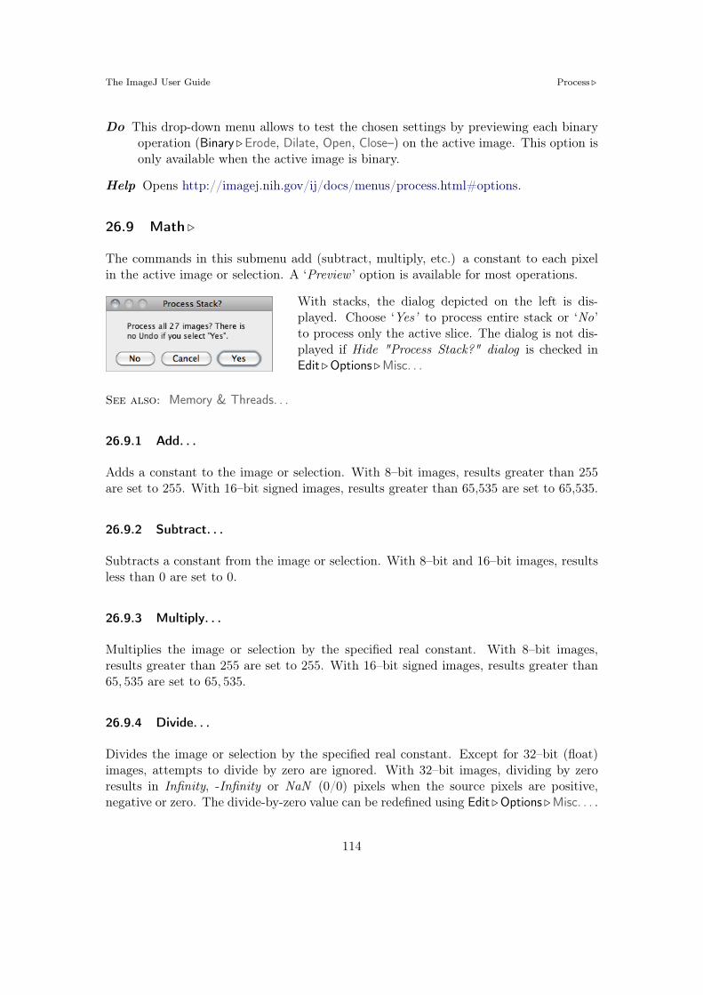
The ImageJ User Guide Process !
Do This drop-down menu allows to test the chosen settings by previewing each binaryoperation (Binary !Erode, Dilate, Open, Close–) on the active image. This option isonly available when the active image is binary.
Help Opens http://imagej.nih.gov/ij/docs/menus/process.html#options.
26.9 Math !
The commands in this submenu add (subtract, multiply, etc.) a constant to each pixelin the active image or selection. A ‘Preview ’ option is available for most operations.
With stacks, the dialog depicted on the left is dis-played. Choose ‘Yes’ to process entire stack or ‘No’to process only the active slice. The dialog is not dis-played if Hide "Process Stack?" dialog is checked inEdit !Options !Misc. . .
See also: Memory & Threads. . .
26.9.1 Add. . .
Adds a constant to the image or selection. With 8–bit images, results greater than 255are set to 255. With 16–bit signed images, results greater than 65,535 are set to 65,535.
26.9.2 Subtract. . .
Subtracts a constant from the image or selection. With 8–bit and 16–bit images, resultsless than 0 are set to 0.
26.9.3 Multiply. . .
Multiplies the image or selection by the specified real constant. With 8–bit images,results greater than 255 are set to 255. With 16–bit signed images, results greater than65, 535 are set to 65, 535.
26.9.4 Divide. . .
Divides the image or selection by the specified real constant. Except for 32–bit (float)images, attempts to divide by zero are ignored. With 32–bit images, dividing by zeroresults in Infinity, -Infinity or NaN (0/0) pixels when the source pixels are positive,negative or zero. The divide-by-zero value can be redefined using Edit !Options !Misc. . . .
114

The ImageJ User Guide Process !
26.9.5 AND. . .
Does a bitwise AND of the image and the specified binary constant.
26.9.6 OR. . .
Does a bitwise OR of the image and the specified binary constant.
26.9.7 XOR. . .
Does a bitwise XOR of the image and the specified binary constant.
26.9.8 Min. . .
Pixels in the image with a value less than the specified constant are replaced by theconstant.
26.9.9 Max. . .
Pixels in the image with a value greater than the specified constant are replaced by theconstant.
26.9.10 Gamma. . .
Applies the function f(p) = (p/255)" # 255 to each pixel(p) in the image or selection, where 0.1 % # & 5.0. ForRGB images, this function is applied to all three colorchannels. For 16–bit images, the image min and maxare used for scaling instead of 255.
See also: GammaCorrectionTool macro
26.9.11 Set. . .
Fills the image or selection with the specified value.
26.9.12 Log
For 8–bit images, applies the function f(p) = ln(p)#255/ ln(255) to each pixel (p) in theimage or selection. For RGB images, this function is applied to all three color channels.For 16–bit images, the image min and max are used for scaling instead of 255. For floatimages, no scaling is done. To calculate log10 of the image, multiply the result of thisoperation by 0.4343 (1/ ln(10)).
115

The ImageJ User Guide Process !
26.9.13 Exp
Performs an exponential transform on the active image or selection.
26.9.14 Square
Performs a square transform on the active image or selection.
26.9.15 Square Root
Performs a square root transform on the active image or selection.
26.9.16 Reciprocal
Generates the reciprocal of the active image or selection. Only works with 32–bit floatimages.
26.9.17 NaN Background
Sets non-thresholded pixels in 32–bit float images to the NaN (Not a Number) value. Forfloat images, the Apply option in Image !Adjust !Threshold. . . [T] runs this command.
Pixels with a value of Float.NaN (0f/0f), Float.POSITIVE_INFINITY (1f/0f) or Float.NEGATIVE_INFINITY (-1f/0f) are ignored when making measurements on 32–bit floatimages.
26.9.18 Abs
Generates the absolute value of the active image or selection. Works only with 32–bitfloat or signed 16–bit image images.
26.9.19 Macro. . .
This command performs image arith-metic using an expression specified bythe user [23]. It can be used to createfully-synthetic images or to performprecise pixel manipulations on exist-ing images. The MathMacroDemomacro demonstrates the usage of thiscommand.
See also: Expression plugin
116

The ImageJ User Guide Process !
26.10 FFT !
The commands in this submenu support frequency domain display, editing and process-ing. They are based on an implementation of the 2D Fast Hartley Transform (FHT)contributed by Arlo Reeves, the author of the ImageFFT spino" of NIH Image.1
The frequency domain image is stored as 32–bit float FHT attached to the 8–bit imagethat displays the power spectrum. Commands in this submenu, such as Inverse FFT, op-erate on the 32–bit FHT, not on the 8–bit power spectrum. All other ImageJ commandsonly ‘see’ the power spectrum.
Two FFT dedicated tutorials are available on the ImageJ website: FFT Measurementsand FFT Filtering.
26.10.1 FFT
Computes the Fourier transform and displays the power spectrum. Polar coordinates ofmeasured point selections are recorded by Analyze !Measure. . . [m].
If the mouse is over an active frequency domain (FFT) window, its location is displayedin polar coordinates. The angle is expressed in degrees, while the radius is expressedin pixels per cycle (p/c). The radius is expressed in [units] per cycle (e.g. mm/c) if thespatial scale of the image was defined using Image !Properties. . . [P] or Analyze ! SetScale. . .
26.10.2 Inverse FFT
Computes the inverse Fourier transform. You can filter or mask spots on the transformed(frequency domain) image and do an inverse transform to produce an image which onlycontains the frequencies selected or which suppresses the frequencies selected. Use Im-ageJ’s selection tools and fill / clear commands to draw black or white areas that maskportions of the transformed image. Black areas (pixel value = 0) cause the correspond-ing frequencies to be filtered (removed) and white areas (pixel value = 255) cause thecorresponding frequencies to be passed. It is not, however, possible to both filter andpass during the same inverse transform.
Note that areas to be filtered in the frequency domain image must be zero filled andareas to be passed must be filled with 255. You can verify that this is the case by movingthe cursor over a filled area and observing that the values displayed in the status bar areeither 0 or 255.
With o"-center selections, the same spatial frequency appears twice in the power spec-trum, at points opposite from the center. It is su#cient to fill / clear only one of these.
1Bob Dougherty’s 3D Fast Hartley Transform plugin performs 3D FHTs
117

The ImageJ User Guide Process !
OriginalPower spectrumwith mask that
filters lowfrequencies
Result of inversetransform
Power spectrumwith mask that
passes lowfrequencies
Result of inversetransform
FFT: Example of low frequencies filtering.
Original Edited powerspectrum Inverse transform Power spectrum
after filtering
FFT: Example of low frequencies filtering.
26.10.3 Redisplay Power Spectrum
Recomputes the power spectrum from the frequency domain image (32–bit FHT). Thiscommand allows you to start over after mis-editing the 8–bit power spectrum image.
26.10.4 FFT Options. . .
Displays the FFT Options dialog box. The first groupof checkboxes specifies which image(s) are created by theFFT command:
Display FFT Window The standard output. It con-sists of an 8–bit image of the power spectrum andthe actual data, which remain invisible for the user.The power spectrum image is displayed with loga-rithmic scaling, enhancing the visibility of compo-nents that are weakly visible. The actual data areused for the Inverse FFT command.
Display Raw Power Spectrum The power spectrum without logarithmic scaling.
Display Fast Hartley Transform The internal format used by the command, whichis based on a Hartley transform rather than Fourier transform.
118

The ImageJ User Guide Process !
Display Complex Fourier Transform A stack with two slices for the real and imag-inary parts of the FFT.
Do Forward Transform If checked, the current image is transformed immediatelywhen closing the FFT Options dialog.
26.10.5 Bandpass Filter. . .
Removes high spatial frequencies (blur-ring the image) and low spatial frequen-cies (similar to subtracting a blurred im-age). It can also suppress horizontalor vertical stripes that were created byscanning an image line by line [24].
The Bandpass Filter uses a special algo-rithm to reduce edge artifacts (before theFourier transform, the image is extendedin size by attaching mirrored copies ofimage parts outside the original image,thus no jumps occur at the edges).
Filter Large Structures Down to Smooth variations of the image with typical sizesof bright or dark patches larger than this value are suppressed (background).
Filter Large Structures Up to Determines the amount of smoothing. Objects in theimage smaller than this size are strongly attenuated. Note that these values areboth half the spatial frequencies of the actual cuto". The cuto" is very soft, sothe bandpass will noticeably attenuate even spatial frequencies in the center of thebandpass unless the di"erence of the two values is large (say, more than a factor of5 or so).
Suppress Stripes Select whether to eliminate Horizontal or Vertical stripes. Removalof horizontal stripes is similar to subtracting an image that is only blurred in thehorizontal direction from the original.
Tolerance of Direction This is for Suppress Stripes ; higher values remove shorterstripes and/or stripes that are running under an angle with respect to the hor-izontal (vertical) direction.
Autoscale After Filtering If checked, puts the lowest intensity to 0 and the highestintensity to 255, preserving all intensities.
Saturate Image when Autoscaling If checked, allows some intensities to go into sat-uration, and produces a better visual contrast. Saturate Image when Autoscalingonly has an e"ect when Autoscale After Filtering is enabled.
119

The ImageJ User Guide Process !
Display Filter If checked, shows the filter generated. Note that this disables Undo ofthe filter operation on the original image.
26.10.6 Custom Filter. . .
This command does Fourier space filtering of theactive image using a user-supplied spatial domain(non-FFT) image as the filter.
This image will be converted to 8–bit. For pixels that have a value of 0, the corre-sponding spatial frequencies will be blocked. Pixel with values of 255 should be usedfor passing the respective spatial frequencies without attenuation. Note that the filtershould be symmetric with respect to inversion of the center: Points that are opposite ofthe center point (defined as x = width/2, y = height/2) should have the same value.Otherwise, artifacts can occur. For some examples, see the FFTCustomFilterDemo andFFTRemoveStreaks macros.
26.10.7 FD Math. . .
This command correlates, convolves or deconvolvestwo images.
It does this by converting Image1 and Image2 tothe frequency domain, performing conjugate multi-plication or division, then converting the result backto the space domain. These three operations in thefrequency domain are equivalent to correlation, con-volution and deconvolution in the space domain.
Refer to the DeconvolutionDemo and MotionBlur-Removal macros for examples.
120

The ImageJ User Guide Process !
26.10.8 Swap Quadrants
FFTOriginal Swapped
Non-FFTOriginal Swapped
This command transforms between the ‘user friendly’ dis-play of Fourier transforms with the lowest frequencies atthe center and the ‘native’ form with the lowest frequenciesat the four corners.
Swap Quadrants swaps quadrants I with III and II with IV(counter-clockwise starting from ‘Northeast’) so that pointsnear the center are moved towards the edge and vice versa.Another way to see this command is to imagine that theimage is periodically repeated and the origin is shifted bywidth/2 in x and by height/2 in y direction.
For Fourier transforms, Swap Quadrants a"ects only the image displayed, not the actualFHT data. Therefore, editing an image with swapped quadrants for filtering or maskingmay lead to undesired results.
26.11 Filters !
This submenu contains miscellaneous filters (including those installed by the Plugins !Utilities ! Install Plugin. . . command).
More information on image filters can be obtained by looking up related keywords (convo-lution, Gaussian, median, mean, erode, dilate, unsharp, etc.) on the Hypermedia ImageProcessing Reference index.
See also: Memory & Threads. . .
26.11.1 Convolve. . .
Does spatial convolution using a kernel enteredinto a text area.
A kernel is a matrix whose center correspondsto the source pixel and the other elements cor-respond to neighboring pixels. The destinationpixel is calculated by multiplying each sourcepixel by its corresponding kernel coe#cient andadding the results. If needed, the input image ise"ectively extended by duplicating edge pixelsoutward. There is no arbitrary limit to the sizeof the kernel but it must be square and have anodd width.
121

The ImageJ User Guide Process !
Rows in the text area must all have the same number of coe#cients, the rows must beterminated with a carriage return, and the coe#cients must be separated by one or morespaces. Kernels can be pasted into the text area using Ctrl V .
Checking Normalize Kernel causes each coe#cient to be divided by the sum of thecoe#cients, preserving image brightness.
The kernel shown is a 9#9 “Mexican hat”, which does both smoothing and edge detectionin one operation. Note that kernels can be saved as a text file by clicking on the ‘Save’button, displayed as an image using File ! Import !Text Image. . . , scaled to a reasonablesize using Image !Adjust !Size. . . and plotted using Analyze !Surface Plot. . .
See also: ConvolutionDemo macro
26.11.2 Gaussian Blur. . .
This filter uses convolution with a Gaussian function forsmoothing [26].
Sigma is the radius of decay to e$0.5 (! 61%), i.e., the stan-dard deviation ($) of the Gaussian (this is the same as inAdobe®Photoshop®, but di"erent from ImageJ versions till1.38q, in which radius was 2.5#$ (cf. GaussianBlur.java).
Like all ImageJ convolution operations, it assumes that out-of-image pixels have a valueequal to the nearest edge pixel. This gives higher weight to edge pixels than pixels insidethe image, and higher weight to corner pixels than non-corner pixels at the edge. Thus,when smoothing with very high blur radius, the output will be dominated by the edgepixels and especially the corner pixels (in the extreme case, with a blur radius of e.g.1020, the image will be replaced by the average of the four corner pixels).
For increased speed, except for small blur radii, the lines (rows or columns of the image)are downscaled before convolution and upscaled to their original length thereafter.
See also: Accurate Gaussian Blur plugin, AnimatedGaussianBlur macro
26.11.3 Median. . .
Reduces noise in the active image by replacing each pixel with the median of the neigh-boring pixel values.
26.11.4 Mean. . .
Smooths the current image by replacing each pixel with the neighborhood mean.
122

The ImageJ User Guide Process !
26.11.5 Minimum. . .
This filter does grayscale erosion by replacing each pixel in the image with the smallestpixel value in that pixel’s neighborhood.
Binary !Erode
26.11.6 Maximum. . .
This filter does grayscale dilation by replacing each pixel in the image with the largestpixel value in that pixel’s neighborhood.
Binary !Dilate
26.11.7 Unsharp Mask. . .
Sharpens and enhances edges by subtracting ablurred version of the image (the unsharp mask)from the original.
Unsharp masking subtracts a blurred copy of theimage and rescales the image to obtain the samecontrast of large (low-frequency) structures as in theinput image. This is equivalent to adding a high-pass filtered image and thus sharpens the image.
Radius The standard deviation ($ blur radius, cf. Gaussian Blur. . . ) of the Gaussianblur that is subtracted. Increasing the Gaussian blur radius will increase contrast.
Mask Weight Determines the strength of filtering, whereby MaskWeight = 1 wouldbe an infinite weight of the high-pass filtered image that is added. Increasing theMask Weight value will provide additional edge enhancement.
26.11.8 Variance. . .
Highlights edges in the image by replacing each pixel with the neighborhood variance.
26.11.9 Show Circular Masks. . .
Generates a stack containing examples of the circular masks used by the Median. . . ,Mean. . . , Minimum. . . , Maximum. . . , and Variance. . . filters for various neighborhoodsizes.
123

The ImageJ User Guide Process !
26.12 Batch !
This submenu allows the execution of commands in a series of images without manualintervention.
Batch ! commands are non-recursive, i.e., they are applied to all the images of the chosenInput folder but not its subfolders. Nevertheless a directory hierarchy can be transversedusing ImageJ macro language (cf. BatchProcessFolders macro).
Three critical aspects to keep in mind when performing batch operations that modifyprocessed images:
– Files can be easily overwritten since the batch processor will silently override ex-isting files with the same name.
– The destination Output folder should have adequate disk space to receive the cre-ated images.
– In the case of non-native formats, batch operations will be influenced by the be-havior of the reader plugin or library (cf. Non–native Formats).
26.12.1 Measure. . .
This command measures all the images in a user-specified folder, by running the Analyze !Measure. . . [m] command in all images of the chosen directory.
Note that measurements are performed on non thresholded images. In the case of TIFFimages saved with active selections measurements are performed on the ROI and not thewhole image.
See also: Analyze !Set Measurements. . . , Batch !Macro. . .
26.12.2 Convert. . .
Batch converts and/or resizes multipleimages from a specified folder.
Input... Selects the source folder con-taining the images to be processed.
Output... Selects the destination folderwhere the processed images will bestored.
124

The ImageJ User Guide Process !
Output Format Specifies the output format that can be set to TIFF, 8–bit TIFF,JPEG, GIF, PNG, PGM, BMP, FITS, Text Image, ZIP or Raw (cf. Image Typesand Image Formats and File !Save As ! submenu).
Interpolation The resampling method to be used in case Scale Factor is not 1.00 (cf.Image ! Size. . . and Image !Scale. . . [E]).
Scale Factor Specifies if images should be resized (cf. Image !Scale. . . [E]).
26.12.3 Macro. . .
Runs a macro over all the imagesin a specified folder.
Input... Selects the source foldercontaining the images to beprocessed.
Output... Selects the destinationfolder where the processedimages will be stored.
Output Format Specifies theoutput format that can beset to TIFF, 8–bit TIFF,JPEG, GIF, PNG, PGM,BMP, FITS, Text Image,ZIP or Raw (cf. ImageTypes and Image For-mats and File !Save As !submenu).
Add Macro Code This drop-down menu contains macro snippets that can be combinedto create the processing macro. Other statements can be pasted from the macrorecorder or ImageJ’s editor while the dialog box is opened [27]. Previously writtenmacros can be imported using Open. . . When editing the macro beware of anystatements that may interfere with the normal operation of the batch processor(such as Close() or Open() calls).
Test Tests the macro on the first image of the Input . . . folder (the processed image willbe displayed).
Open. . . Imports previously written macros.
Save. . . Saves the assembled macro.
Help Opens http://imagej.nih.gov/ij/docs/menus/file.html#raw.
125

The ImageJ User Guide Process !
See also: Plugins !Macros !Record. . . , Batch !Virtual Stack. . .
26.12.4 Virtual Stack. . .
This command, that shares the same interface of Batch !Macro. . . (cf. BatchProcesser.java),allows virtual stack manipulations. E.g., Cropping a virtual stack can be performed byexecuting the following steps:
1. Open a virtual stack
2. Run Process !Batch !Virtual Stack. . .
3. Select an Output folder and Output format
4. Select ‘Crop’ from the Add Macro Code drop-down menu
5. Edit the macro code as needed and press the Test button to verify the macro
6. Click Process to create the cropped virtual stack
Note that cropped images are not loaded into memory but are saved to disk as they arecropped (see Virtual Stacks).
26.13 Image Calculator. . .
Performs arithmetic and logical operationsbetween two images selected from popupmenus.
Image1 or both Image1 and Image2 can bestacks. If both are stacks, they must havethe same number of slices. Image1 and Im-age2 do not have to be the same data typeor the same size.
With 32–bit (float) images, pixels resultingfrom division by zero are set to Infinity, orto NaN (Not a Number) if a zero pixel isdivided by zero. The divide-by-zero valuecan be redefined in Edit !Options !Misc. . .
Operation Selects one of the thirteen available operators (see Image Calculator. . . op-erations).
Create New Window If checked, a new image or stack will be created to hold theresult. Otherwise, the result of the operation replaces some or all of Image1.
126

The ImageJ User Guide Process !
32–bit (float) Result If checked, the source images will be converted to 32–bit floatingpoint before the specified operation is performed.
Help Opens http://imagej.nih.gov/ij/docs/menus/process.html#calculator.
Image Calculator. . . operations. On these examples source and destination images (8–bitgrayscale) are displayed with inverted LUTs (White= 0; Black= 255) (cf. Lookup Tables ! sub-menu). Note that calculations between images can also be performed using copy and paste andthe Edit !Paste Control. . . command.
Source image (img1): Destination image (img2):
Operator Result Operator Result
Add: Min:img1 = img1 + img2 img1 = min(img1, img2)
Subtract: Max:img1 = img1" img2 img1 = max(img1, img2)
Multiply: Average:img1 = img1# img2 img1 = (img1 + img2)/2
Divide: Di!erence:img1 = img1÷ img2 img1 = |img1" img2|
AND: Copy:img1 = img1 ' img2 img1 = img2
OR: Transparent–zeroimg1 = img1 ( img2
XOR:img1 = img1) img2
127

The ImageJ User Guide Process !
26.14 Subtract Background. . .
Removes smooth continuous backgrounds from gelsand other images.
Based on the ‘rolling ball’ algorithm by Stanley Stern-berg (see Sternberg S, Biomedical image processing,IEEE Computer, Jan 1983). Imagine a 3D surfacewith the pixel values of the image being the height,then a ball rolling over the back side of the surface cre-ates the background. If Sliding Paraboloid is checked,the command will use a more robust implementa-tion of the algorithm that uses an approximation ofa paraboloid of rotation instead of a ball.
Rolling Ball Radius The radius of curvature of the paraboloid. As a rule of thumb,for 8–bit or RGB images it should be at least as large as the radius of the largestobject in the image that is not part of the background. Larger values will alsowork unless the background of the image is too uneven. For 16–bit and 32–bitimages with pixel value ranges di"erent from 0–255, the radius should be inverselyproportional to the pixel value range (e.g., for 16–bit images (pixel values 0–65535),typical values of the radius are around 0.2 to 5).
Light Background Allows the processing of images with bright background and darkobjects.
Separate Colors (RGB images only) If unchecked, the operation will only a"ect thebrightness, leaving the hue and saturation untouched.
Create Background (Don’t Subtract) If checked, the output is not the image withthe background subtracted but rather the background itself. This option is usefulfor examining the background created (in conjunction with the Preview option).Create Background can be also used for custom background subtraction algorithmswhere the image is duplicated and filtered (e.g. removing ‘holes’ in the background)before creating the background and finally subtracting it with Process ! Image Cal-culator. . .
Sliding Paraboloid If checked, the ‘rolling ball’ is replaced by a paraboloid that has thesame curvature at the apex as a ball of that radius. This option allows any value ofthe radius> 0.0001 (The ‘rolling ball’ algorithm requires a radius of at least 1). The‘sliding paraboloid’ typically produces more reliable corrections since the ‘rollingball’, a legacy algorithm, is prone to edge artifacts. E.g., to reduce the computingtime the ‘rolling ball’ algorithm downscales the image in a way that is not reallyconsistent. The ‘sliding paraboloid’ algorithm does not use downscaling and thusproduces no downscaling artifacts. Nevertheless, the ‘sliding paraboloid’ is also anapproximation, since it does not really use a paraboloid (an exact implementation
128

The ImageJ User Guide Process !
would require a great computing e"ort) but it rather slides parabolae in di"erentdirections over the image.
Disable Smoothing For calculating the background (‘rolling the ball’), images aremaximum-filtered (3#3 pixels) to remove outliers such as dust and then smoothedto reduce noise (average over (3#3 pixels). With Disable Smoothing checked, theunmodified image data are used for creating the background. Check this option tomake sure that the image data after subtraction will never be below the background.
Help Opens http://imagej.nih.gov/ij/docs/menus/process.html#background.
See also: How to correct background illumination in brightfield microscopy by G. Lan-dini, Auto Local Threshold, Background subtractor, Rolling Ball BackgroundSubtraction (the plugin that implemented this command in versions up to1.39e)
Original Image Corrected Image
Process ! Subtract Background. . . command. This command uses a ‘sliding paraboloid’ or alegacy ‘rolling ball’ algorithm that can be used to correct for uneven illuminated background asshown in the profiles (Analyze !Plot Profile [k]) below each image. The radius should be set toat least the size of the largest object that is not part of the background.
26.15 Repeat Command [R]
Reruns the previous command. The Edit !Undo and File !Open commands are skipped.
See also: Undo and Redo
129

The ImageJ User Guide Analyze !
27 Analyze !
This menu contains commands related to statistical measurements on image data, profileand histogram plotting and plugins related to image analysis.
27.1 Measure. . . [m]
Based on the selection type, calculates and displays on the Results table either areastatistics, line lengths and angles, or point coordinates. Performed measurements can bespecified in the Set Measurements. . . dialog box.
Area statistics are calculated for the complete image if there is no selection or for aselected subregion defined by one of the first four tools in the toolbar (cf. Tools). Forlinear selections (Straight, Segmented and Freehand lines, cf. Line Selection Tools) lengthand angle (straight lines only) are also calculated. For Point selections (cf. Point Tooland Multi-point Tool), the X and Y coordinates are recorded. Note that Measure. . . [m]will paint (invasively) a mark over the measured point in foreground color unless MarkWidth in the Point Tool options dialog box is set to zero (cf. Point Tool).
With RGB images, results are calculated using brightness values. RGB pixels areconverted to brightness values using the formula value = (red + green + blue)/3 orvalue = 0.299 # red + 0.587 # green + 0.114 # blue if Weighted RGB Conversions ischecked in Edit !Options !Conversions. . . .
Intensity statistics (Mean, Modal, Median, Min. & Max. Gray Value, Standard Deviationand Integrated Density) can be performed on area, line and multi-point selections.
With area selections, the following parameters can be recorded: Area, Center of Mass,Centroid, Perimeter, Bounding Rectangle, Shape Descriptors, Fitted Ellipse, Feret’s Di-ameter, Skewness, Kurtosis and Area Fraction.
With line selections, the following parameters can be recorded: Length, Angle (straightlines only), and Bounding Rectangle. The mean, standard deviation, etc. are calculatedfrom the values of the pixels along the line.
See also: The Results Table, Analyze Particles. . . , Summarize, Distribution. . . , Set Mea-surements. . . , Batch !Measure. . .
130

The ImageJ User Guide Analyze !
27.2 Analyze Particles. . .Improvedin IJ 1.44
This command counts and measuresobjects in binary or thresholded im-ages (Image !Adjust !Threshold. . . [T] orColor Threshold. . . ). Analysis is per-formed on the existing area selection oron the entire image if no selection ispresent.
It works by scanning the image or se-lection until it finds the edge of an ob-ject. It then outlines the object using theWand Tool, measures it using the Mea-sure. . . [m] command, fills it to make itinvisible, then resumes scanning until itreaches the end of the image or selection.Press Esc to abort this process.
Exclude on Edges Include Holes Size: 0–50 Circ.: 0.5–1.0
Original (thresholded)
Size: 0–% Circ.: 0.0–0.5 Size: 0–% Circ.: 0.0–0.3 Size: 50–% Circ.: 0.5–1.0
Particle Analyzer (Analyze !Analyze Particles. . . ). Features of thresholded images can beextracted by specifying suitable Size and Circularity ranges and/or by choosing if particles shouldbe traced by their outer edge or by flood filling (Include Holes checkbox).
Size Particles with size (area) outside the range specified in this field are ignored. Valuesmay range between 0 and ‘Infinity’. For spatial scaled images (cf. Set Scale. . . )
131

The ImageJ User Guide Analyze !
values are expressed in physical size square units or in pixels if Pixel Units ischecked. Enter a single value and particles smaller than that value will be ignored.
Circularity Particles with size circularity values outside the range specified in this fieldare also ignored. Circularity (4% # [Area]
[Perimeter]2 , cf. Set Measurements. . . ) rangesfrom 0 (infinitely elongated polygon) to 1 (perfect circle).
Show This drop-down menu specifies which image (or overlay) should ImageJ displayafter the analysis. Note that with IJ 1.44e and later, the particle analyzer willdisplay a blank image when the count of detected particles is zero and Show is notNothing.
Nothing Neither images nor overlays will be displayed.Outlines 8–bit image containing numbered outlines of the measured particles
(graylevels: Outlines: 0; Labels: 1; Background : 255). If In situ Show is checked,the original image will be replaced by this image.
Bare Outlines 8–bit image containing simple outlines of the measured particlesNew inIJ 1.44
without labels (graylevels: Outlines: 0; Background : 255). If In situ Show ischecked, the original image will be replaced by this image.
Masks 8–bit binary image containing filled outlines of the measured particles(graylevels: Masks: 0; Background : 255). If In situ Show is checked, the origi-nal image will be replaced by this image.
Ellipses 8–bit binary image containing the best fit ellipse (cf. Edit !Selection !FitEllipse) of each measured particle (graylevels: Ellipses: 0; Background : 255). IfIn situ Show is checked, the original image will be replaced by this image.
Count Masks 16–bit image containing filled outlines of the measured particlespainted with a grayscale value corresponding to the particle number. If Insitu Show is checked, the original image will be replaced by this image.
Overlay Outlines Displays outlines of the measured particles in the image over-New inIJ 1.44
lay. Note that previously added overlays will be removed.Overlay Masks Displays filled outlines of the measured particles in the image
New inIJ 1.44
overlay. Note that previously added overlays will be removed.
Display Results If checked, the measurements for each particle will be displayed in theResults table.
Clear Results If checked, any previous measurements listed in the Results table willbe cleared.
Summarize If checked, the particle count, total particle area, average particle size, areafraction and the mean of all parameters listed in the Set Measurements. . . dialogbox will be displayed in a separate Summary table. Note that while single images‘Summaries’ are output to the same Summary table, stack Summaries are printed
132

The ImageJ User Guide Analyze !
in dedicated tables (named Summary of [stack title]). Also, note that descriptivestatistics on Results measurements can be obtained at any time using the Summarizecommand.
Add to Manager If checked, the measured particles will be added to the ROI Man-ager. . .
Exclude on Edges If checked, particles touching the edge of the image (or selection)will be ignored.
Include Holes If checked, interior holes will be included. Disable this option to excludeinterior holes and to measure particles enclosed by other particles. When this optionis enabled, ImageJ finds the extent of each particle by tracing the outer edge. Whenit is disabled, ImageJ finds the extent by flood filling.
Record Starts This option allows plugins and macros to recreate particle outlines usingthe doWand(x,y) macro function. The CircularParticles macro demonstrates howto use this feature.
In situ Show If checked, the original image will be replaced by the binary mask spec-New inIJ 1.44
ified in the Show drop-down menu. Note that this option does not apply toOverlay Outlines and Overlay Masks that are always displayed as non-destructiveimage overlays on the measured image.
Help Opens http://imagej.nih.gov/ij/docs/menus/analyze.html#ap.
See also: Particle Remover plugin, 4/8–Connected Particle Analysis
27.3 Summarize
For each column in the results table, calculates and displays the mean, standard de-viation, minimum and maximum of the values in that column. This command is alsoavailable by right-clicking on The Results Table.
See also: Analyze Particles. . . , Distribution. . .
133

The ImageJ User Guide Analyze !
Original (thresholded) Outlines Bare Outlines Masks
Ellipses Count Masks Overlay Outlines Overlay Masks
Display options of Particle Analyzer (Analyze !Analyze Particles. . . ), IJ 1.44l.
27.4 Distribution. . .
Produces a relative frequency his-togram from the data of a chosencolumn of the Results table [28].
Use the List or Copy buttons to savethe histogram data. Mouse over thehistogram bars to read the counts foreach bin on the window’s lower rightcorner. Analyze !Histogram [h] de-scribes in more detail ImageJ’s his-togram window.
This command is also available byright-clicking on The Results Table.
Parameter Specifies the parameter in the Results table to be analyzed.
Data points The number of rows that will be analyzed (informative)
Automatic binning If checked, ImageJ will use the method described by David Scottto assess the optimal histogram bin width (see Scott DW, Optimal and data-based
134

The ImageJ User Guide Analyze !
histograms. Biometrika, 66(3):605–610, Jan 1979). If unchecked, the number ofbins can be set with Specify bins and the starting and ending limits of the histogramwith range.
See also: Distribution Plotter, a macro that plots relative and cumulative frequencieson a double Y-axis graph
27.5 Label
This command labels the active selection with the current measurement counter value,i.e., the number of rows present in the Results table. Selection outline and label (at theselection centroid) are drawn invasively using current foreground/background colors. Asfor Edit !Draw [d], Use the Edit !Options ! Line Width. . . command, or double click onthe line tool, to change the width of selection’s outline.Selections can be labelled if they were previously analyzed (Analyze Particles. . . or Mea-sure. . . [m] commands) and the parameter Centroid (cf. Set Measurements. . . ) extractedin the Results table.
See also: Color Picker, XIV
27.6 Clear Results
Erases the results table and resets the measurement counter. This command is alsoavailable by right-clicking on The Results Table.
27.7 Set Measurements. . .
Use this dialog box to specify which measure-ments are recorded by Analyze !Measure. . .[m], ROI Manager’s Measure command (cf.ROI Manager. . . ) and Analyze !Analyze Par-ticles. . . Measurements are performed on thecurrent selection, the entire active image if noselection is present. For thresholded images,measurements can be restricted to highlightedpixels if Limit to Threshold is checked.
This command is also available by right-clicking on The Results Table.
The dialog contains two groups of checkboxes:The first group controls the type of measure-ments that are printed to the Results table.The second group controls measurement set-tings.
135

The ImageJ User Guide Analyze !
The eighteen checkboxes of the first group are:
Area Area of selection in square pixels or in calibrated square units (e.g., mm2, µm2,etc.) if Analyze !Set Scale. . . was used to spatially calibrate the image.
Mean Gray Value Average gray value within the selection. This is the sum of the grayvalues of all the pixels in the selection divided by the number of pixels. Reported incalibrated units (e.g., optical density) if Analyze !Calibrate. . . was used to calibratethe image. For RGB images, the mean is calculated by converting each pixel tograyscale using the formula gray = (red + green + blue)/3 or gray = 0.299# red +0.587 # green + 0.114 # blue if Weighted RGB Conversions is checked in Edit !Options !Conversions. . .
Standard Deviation Standard deviation of the gray values used to generate the meangray value. Uses the Results table heading StdDev.
Modal Gray Value Most frequently occurring gray value within the selection. Corre-sponds to the highest peak in the histogram. Uses the heading Mode.
Min & Max Gray Level Minimum and maximum gray values within the selection.
Centroid The center point of the selection. This is the average of the x and y coordi-nates of all of the pixels in the image or selection. Uses the X and Y headings.
Center of Mass This is the brightness-weighted average of the x and y coordinatesall pixels in the image or selection. Uses the XM and YM headings. Thesecoordinates are the first order spatial moments.
Perimeter The length of the outside boundary of the selection. Uses the headingImprovedin IJ 1.44
Perim.. With IJ 1.44f and later, the perimeter of a composite selection is calculatedby decomposing it into individual selections. Note that the composite perimeterand the sum of the individual perimeters may be di"erent due to use of di"erentcalculation methods.
Bounding Rectangle The smallest rectangle enclosing the selection. Uses the headingsBX, BY, Width and Height, where BX and BY are the coordinates of the upperleft corner of the rectangle.
Fit Ellipse Fits an ellipse to the selection. Uses the headings Major, Minor andAngle. Major and Minor are the primary and secondary axis of the best fittingellipse. Angle is the angle between the primary axis and a line parallel to theX-axis of the image. The coordinates of the center of the ellipse are displayed asX and Y if Centroid is checked. Note that ImageJ cannot calculate the major andminor axis lengths if Pixel Aspect Ratio in the Analyze !Set Scale. . . dialog is not1.0. There are several ways to view the fitted ellipse:
136

The ImageJ User Guide Analyze !
1. The Edit ! Selection !Fit Ellipse command replaces an area selection with thebest fit ellipse.
2. The DrawEllipse macro draws (destructively) the best fit ellipse and the majorand minor axis.
3. Select Ellipses from the Show: drop-down menu in the particle analyzer (An-alyze !Analyze Particles. . . ) and it will draw the ellipse for each particle in aseparate window.
Shape Descriptors Calculates and displays the following shape descriptors:
Circularity 4% # [Area][Perimeter]2 with a value of 1.0 indicating a perfect circle. As
the value approaches 0.0, it indicates an increasingly elongated shape. Valuesmay not be valid for very small particles. Uses the heading Circ.
Aspect Ratio The aspect ratio of the particle’s fitted ellipse, i.e., [Major Axis][Minor Axis] . If
Fit Ellipse is selected the Major and Minor axis are displayed. Uses theheading AR.
Roundness 4 # [Area]#![Major axis]2 or the inverse of Aspect Ratio. Uses the heading
Round.Solidity [Area]
[Convex area] ; Note that the Edit !Selection !Convex Hull command makesan area selection convex.
Feret’s Diameter The longest distance between any two points along the selectionboundary, also known as maximum caliper. Uses the heading Feret. The angle(0–180 degrees) of the Feret’s diameter is displayed as FeretAngle, as well as theminimum caliper diameter (MinFeret). The length of the object’s projection inthe X (FeretX) and Y (FeretY) direction is also displayed.
Integrated Density The sum of the values of the pixels in the image or selection. ThisImprovedin IJ 1.44
is equivalent to the product of Area and Mean Gray Value. With IJ 1.44c andlater, Raw integrated density (sum of pixel values) is displayed under the head-ing RawIntDen when Integrated density is enabled. The Dot Blot Analysistutorial demonstrates how to use this option to analyze a dot blot assay.
Median The median value of the pixels in the image or selection.
Skewness The third order moment about the mean. The documentation for the Mo-ment Calculator plugin explains how to interpret spatial moments. Uses the head-ing Skew.
Kurtosis The fourth order moment about the mean. Uses the heading Kurt.
Area Fraction For thresholded images is the percentage of pixels in the image or se-lection that have been highlighted in red using Image !Adjust !Threshold. . . [T].For non-thresholded images is the percentage of non-zero pixels. Uses the heading%Area.
137
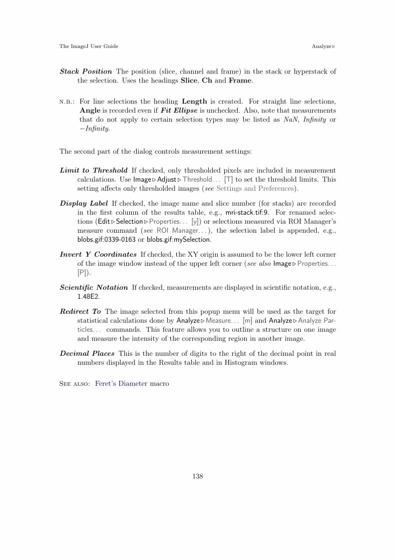
The ImageJ User Guide Analyze !
Stack Position The position (slice, channel and frame) in the stack or hyperstack ofthe selection. Uses the headings Slice, Ch and Frame.
n.b.: For line selections the heading Length is created. For straight line selections,Angle is recorded even if Fit Ellipse is unchecked. Also, note that measurementsthat do not apply to certain selection types may be listed as NaN, Infinity or"Infinity.
The second part of the dialog controls measurement settings:
Limit to Threshold If checked, only thresholded pixels are included in measurementcalculations. Use Image !Adjust !Threshold. . . [T] to set the threshold limits. Thissetting a"ects only thresholded images (see Settings and Preferences).
Display Label If checked, the image name and slice number (for stacks) are recordedin the first column of the results table, e.g., mri-stack.tif:9. For renamed selec-tions (Edit ! Selection !Properties. . . [y]) or selections measured via ROI Manager’smeasure command (see ROI Manager. . . ), the selection label is appended, e.g.,blobs.gif:0339-0163 or blobs.gif:mySelection.
Invert Y Coordinates If checked, the XY origin is assumed to be the lower left cornerof the image window instead of the upper left corner (see also Image !Properties. . .[P]).
Scientific Notation If checked, measurements are displayed in scientific notation, e.g.,1.48E2.
Redirect To The image selected from this popup menu will be used as the target forstatistical calculations done by Analyze !Measure. . . [m] and Analyze !Analyze Par-ticles. . . commands. This feature allows you to outline a structure on one imageand measure the intensity of the corresponding region in another image.
Decimal Places This is the number of digits to the right of the decimal point in realnumbers displayed in the Results table and in Histogram windows.
See also: Feret’s Diameter macro
138

The ImageJ User Guide Analyze !
27.8 Set Scale. . .
Use this dialog to define the spatial scale of the activeimage so measurement results can be presented in cali-brated units, such as mm or µm.
Before using this command, use the straight line selectiontool to make a line selection that corresponds to a knowndistance. Then, bring up the Set Scale. . . dialog, enterthe Known Distance and unit of measurement, then click‘OK’.
ImageJ will have automatically filled in the Distance inPixels field based on the length of the line selection.
Setting Pixel Aspect Ratio to a value other than 1.0 enables support for di"erent horizon-tal and vertical spatial scales, e.g., 100 pixels/cm horizontally and 95 pixels/cm vertically.To set the Pixel Aspect Ratio:
1. Measure the width and height (in pixels) of a digitized object with a known 1:1aspect ratio.
2. Enter the measured width (in pixels) in Distance in Pixels. Enter the known widthin Known Distance.
3. Calculate the aspect ratio by dividing the width by the height and enter it in PixelAspect Ratio
When Global is checked, the scale defined in this dialog is used for all opened imagesduring the current session instead of just the active image, see XVIII.Click to Remove Scale resets Distance in Pixels field and Know Distance to zero and theUnit of Length to ‘pixel’.
See also: Three tutorials showing how to use this command: Examples of Image Anal-ysis Using ImageJ by Larry Reinking, Measuring DNA Contour Lengths andSpatial Calibration (Fiji). The Copy_Pixel_Size plugin
27.9 Calibrate. . .
Use this dialog box to calibrate an image to a set of density standards, for exampleradioactive isotope standards or a calibrated optical density step tablet.Note that to create a calibration curve, the left column must contain a list of measuredmean pixel values and the right column must contain the same number of calibrationstandard values.The ImageJ web site has a tutorial on Optical Density Calibration explaining how tocalibrate an image to an optical density step tablet.
139

The ImageJ User Guide Analyze !
XVIII Global Calibrations
Calibration settings related to spatial (pixel width, height and voxel depth), temporal (frameinterval) and luminance (brightness) information can be set globally, i.e., can be applied to allimages opened during the current session instead of just the active image. The Global flag canbe set in three dialog prompts:
1. Image !Properties. . . [P] (pixel width, height, voxel depth, frame interval)
2. Analyze ! Set Scale. . . (pixel width and height)
3. Analyze !Calibrate. . . (pixel intensity)
Once Global calibration is set, a ‘(G)’ is displayed in allimage titles until ImageJ is closed. A warning message isdisplayed when a calibrated image with conflicting calibra-tion is opened and the Global option is enabled.
Choose Disable Global Calibration to stop using global set-tings or Disable these Messages to keep respecting globalsettings, ignoring the calibration of the newly open image.
1. Before using this command, use Analyze !Clear Results to reset the measurementcounter and use one of the selection tools and Analyze !Measure. . . [m] to recordthe mean gray value of each of the standards.
2. When finished making the measurements, select Analyze !Curve Fitting. . . to dis-play the Calibrate dialog box. To calibrate the image, enter the known standardvalues in the right column. The left column will be already populated with the mea-sured mean gray values. Select a curve fitting method from the popup menu, enterthe unit of measurement, and click ‘OK’. ImageJ will then display the calibrationfunction on a separate window.
3. If the calibration function is not satisfactory, bring up the Calibrate. . . dialog boxagain and select a di"erent curve fitting method.
In addition to the fourteen functions that can be chosen from the drop-down menu(described in Curve Fitting. . . ) two other functions are available that do not require anymeasurement of OD standards:
Uncalibrated OD Causes ImageJ to convert gray values from 8–bit images to uncali-brated optical density values using the function Unc. OD = log10(255/Pixel value).
Pixel Inverter Linear function defined by Inverted pixel = Bit-depth"1"Pixel value,with Bit-depth being 255 for 8–bit images or 65535 for 16–bit images.
140

The ImageJ User Guide Analyze !
See also: XVIII, Image Types and Image Formats, Curve Fitting. . .
27.10 Histogram [h]Improvedin IJ 1.44
Calculates and displays a histogram of the distribution of gray values in the active imageor selection. H is a convenient shortcut for this command1.
The X-axis represents the possible gray values and the Y-axis shows the number of pixelsfound for each gray value. The total pixel Count is also calculated and displayed, as wellas the Mean, standard deviation (StdDev), minimum (Min), maximum (Max ) and modal(Mode) gray value.
The horizontal LUT bar is scaled to re-flect the display range of the image [29].Use the List or Copy buttons to savethe histogram data. Click on Log todisplay a log-scaled version of the his-togram (overlaid in gray).
Value /Count pairs (i.e., grayscalevalue corresponding to the X-axis cur-sor position / the number of pixels thathave that intensity) are displayed on
1This shortcut is not listed on Mac OSX since it conflicts with the system wide shortcut for the ‘Hide’command. It is shown on Windows and Linux and the H shortcut (without holding down Cmd ) doeswork on OS X.
141

The ImageJ User Guide Analyze !
the bottom right while mousing over thehistogram window.
With RGB images, the histogram iscalculated by converting each pixel to
grayscale using the formula gray = (red + green + blue)/3 or gray = 0.299 # red +0.587# green+ 0.114# blue if Weighted RGB Conversions is checked in Edit !Options !Conversions. . . . With 16–bit images, the range of gray values between the Min and Maxvalues is divided into 256 bins. With 32–bit images, the number of bins is specified inthe depicted dialog box.
With any image type, this dialog can be called with Alt H orby holding Alt while clicking on Histogram [h].
Bins Specifies the number of bins.
Use min/max If checked, the X-axis range is determined by theminimum and maximum values in the image or selection. Ifunchecked, X Min and X Max values can be or specified tofix the X-axis range.
Y Max Fixes the Y-axis range. Type ‘Auto’ to have the rangedetermined by the largest bin count.
The getHistogram() and Plot.getValues() macro functions can be used to get the‘value’ and ‘Count’ data displayed when you click the List button (cf. Obtaining His-togram Lists).
Listing 6 Obtaining Histogram Lists with getHistogram() and Plot.getValues().1 // 1. Single images:2 run("Blobs (25K)");3 getHistogram(values , counts , 256);4 for (i=0; i<values.length; i++)5 print(values[i], counts[i]);67 // 2. Entire stacks:8 run("T1 Head (2.4M , 16-bits)");9 run("Histogram", "stack");
10 Plot.getValues(values , counts);11 for (i=0; i<values.length; i++)12 print(values[i], counts[i]);
27.11 Plot Profile [k]
142

The ImageJ User Guide Analyze !
Displays a two-dimensional graph ofthe intensities of pixels along a linewithin the image. The X-axis repre-sents distance along the line and theY-axis is the pixel intensity.
Use the List, Save... or Copy... but-tons to view and save the profiledata. Use Edit !Options !Profile PlotOptions. . . to adjust how plots aregenerated.
For rectangular selections (or line se-lections wider than one pixel), dis-plays a ‘column average plot’, wherethe X-axis represents the horizontal
distance through the selection and the Y-axis the vertically averaged pixel intensity. Toaverage horizontally, hold down Alt or check Vertical Profile in the Edit !Options !ProfilePlot Options. . . dialog box.
See also: Plot Z-axis Profile. . . , Surface Plot. . . , Dynamic Profiler, Oval Profile Plot,Radial Profile Plot, Radial Profile Extended plugins, StackProfilePlot macro
27.12 Surface Plot. . .
Displays a three-dimensional graph of the intensities of pixels in a grayscale or pseudocolor image (non-RGB images). The plot is based on the existing rectangular selectionor on the entire image if no selection is present. A stack of plots can be produced whenthe source image is a stack or hyperstack. In this case, closing the plot stack windowwill abort the plotting process.
Polygon Multiplier Adjusts the number of profiles used to generate the plot.
Draw Wireframe If checked, the outline of each profile will be drawn in black.
Shade If checked, a shaded plot will be generated using the LUT of source image.
Draw Axis If checked, the three axis will be drawn and labeled.
Source Background is Lighter If checked, lighter areas in the source image will rep-resent lower elevations (valleys) while darker areas in the source image will representhigher elevations (peaks).
Fill Plot Background with Black If checked, the plot is drawn with a black back-ground, otherwise white will be used.
143

The ImageJ User Guide Analyze !
One Polygon Per Line If checked, all polygons will be drawn.
Smooth If checked, sharp fluctuations will be smoothed. Note that some plots can befurther improved by adjusting the contrast of the source image or smoothing it.
See also: Plot Profile [k], Interactive 3D Surface Plot plugin (it works with all imagetypes and viewing angle, perspective, scale, lighting and smoothing can beinteractively adjusted), 3D Color Inspector/Color Histogram
27.13 Gels !
Use the commands in this submenu to analyze one-dimensional electrophoretic gels.These commands use a simple graphical method that involves generating lane profileplots, drawing lines to enclose peaks of interest, and then measuring peak areas (i.e.,definite integrals) using the Wand Tool. . . . Note that this technique cannot be used tocompare bands on di"erent gels unless gels are calibrated to known standards.
The commands listed in the this submenu are:
Select First Lane 1 Requires a rectangular selection. Note that lanes are assumed tobe vertical unless the width of the initial selection is at least twice its height.
Select Next Lane 2 To be used after the first rectangular ROI is moved over the ad-jacent lanes. Note that all selections must have the same dimensions.
144

The ImageJ User Guide Analyze !
Plot Lanes 3 Generates the lane profile plots. ImageJ assumes that only one plotis created per analysis. As a consequence, re-running this command more thanonce within the same analysis will cause an error message: “You must first use the‘Select First Lane’ command ”. To recreate plotted profiles use the Re-plot Lanescommand.
Re-plot Lanes Recreates the lane profile plots. If Plot Lanes has not yet been run anerror message is displayed: “The data needed to re-plot the lanes is not available”.
Reset Resets the analysis.
Label Peaks Uses the area measurements obtained with the Wand Tool to label lanepeaks (see Gel Analyzer Options. . . ).
Gel Analyzer Options. . . Use this dialog to control the behavior of the Gel Analyzer.
Vertical /Horizontal scale factor Specify the scale factor at which the laneprofile plots are displayed.
Uncalibrated OD If checked, ImageJ will convert gray values to uncalibratedoptical density values using the function: Unc. OD = log10(255/pixel value).Note that images can be calibrated to, e.g., a calibrated optical density steptablet using the Analyze !Calibrate. . . command.
Label With Percentages If checked, the Label Peaks command will print to theResults table the ‘peak percentage’ and use it to label the plot. The percentagevalue is obtained by dividing the area of each peak by the sum of all measuredpeaks from all lanes.
Invert Peaks If checked, peaks will be inverted, i.e, bands darker than back-ground will have positive peaks, bands lighter than background will have neg-ative peaks. This setting does not change the analysis (see Image ! LookupTables ! Invert LUT).
145

The ImageJ User Guide Analyze !
For practice, refer to the video tutorial on the ImageJ wiki page and use the File !OpenSamples !Gel sample image (1–D gel) to perform the following steps. Note that a copyof the gel image with the lane outlines can be created at any point using the Image !Overlay !Flatten [F] command.
1. Use the rectangular selection tool to outline the first lane. This should be the leftmost lane if the lanes are vertical or the top lane if the lanes are horizontal.
2. Select Gels ! Select First Lane ( 1 ) and the lane will be outlined and ‘Lane 1 selected’displayed in the status bar.
3. Move the rectangular selection right to the next lane (or down if the lanes arehorizontal) and select Gels ! Select Next Lane ( 2 ). The selected lane is outlinedand labeled, and ‘Lane n selected’ is displayed in the status bar.
4. Repeat the previous step for each remaining lane.
5. Select Gels !Plot Lanes ( 3 ) to generate the lane profile plots.
6. Use the Straight Line Selection Tool to draw base lines and/or drop lines so thateach peak of interest defines a closed area (ImageJ will automatically switch to theStraight Line tool). Note that you can hold Shift to constrain lines to be eitherhorizontal or vertical. To access to all the lanes, it may be necessary to scroll theimage vertically using the Scrolling Tool (Hold down the space bar to temporarilyswitch to this tool).
7. For each peak, measure the size by clicking inside the peak with the Wand Tool. Ifnecessary, scroll the image vertically by holding down the space bar and dragging.
8. Select Gels ! Label Peaks to label each measured peak with its size as a percent ofthe total size of the measured peaks.
See also: Calibrate. . . , SinglePanelGelAnalyzer macro, Video tutorial on ImageJ wiki,Luke Miller’s tutorial, Dot Blot Analysis, Dot Blot Analyzer toolset
27.14 Tools !
This submenu provides access to various image analysis plugins.
146

The ImageJ User Guide Analyze !
27.14.1 Save XY Coordinates. . .
Writes to a text file the XY coordinatesand pixel value of all non-background pix-els in the active image. Background isassumed to be the value of the pixel atthe upper left corner of the image. Forgrayscale images, writes three values perline (x, y, and value), separated by spaces.For RGB images, writes five values perline (x, y, red, green and blue). The originof the coordinate system is at the lowerleft corner of the image.
The number and percentage of non-background pixels is printed to the Log window ifSuppress Log output is not checked.
27.14.2 Fractal Box Count...
This command is used to estimate the fractal di-mension (D) of a binary image. D can be usedas a measure of pattern complexity (cell shape,vascularization, textures, etc.) and is speciallyrelevant in cases in which Euclidean measuressuch as diameter or length are not good descrip-tors of complexity.
The command counts the number of boxesof an increasing size needed to cover a onepixel binary object boundary and implementsthe method described in T. G. Smith, Jr., G.D. Lange and W. B. Marks, Fractal Methodsand Results in Cellular Morphology, J NeurosciMethods, 69:1123–126, 1996.
A plot is generated with the log of size on the X-axis and the log of count on the Y-axisand the data is fitted with a straight line. The slope (S) of the line is the negative of thefractal dimension, i.e., D= "slope. ‘Size’ (S) and ‘count’ (C) are printed to the Resultstable. Refer to the source code for additional information.
See also: Fractal Dimension and Lacunarity plugin
147

The ImageJ User Guide Analyze !
27.14.3 Analyze Line Graph
ImageJ can be used to recover numeric coordinatedata from scanned line graphs using the followingprocedure. Steps 2 and 3 are not necessary forbinary (black and white) graphs. For practice, usethe File !Open Samples ! Line Graph sample image.
1. Open the image containing the graph.
2. Open the Threshold. . . [T] tool ( Shift T ).Adjust the threshold so the graph is highlightedin red.
3. Click on Apply (make sure foreground is blackand background is white).
4. Use the Elliptical Selection Tool as an eraser (press Backspace to erase) to isolate a singlecurve (NB: background color must be white, cf. Color Picker. . . [K]).
5. Select the curve by clicking to the left of it with the Wand Tool.
6. Use Edit !Clear Outside to erase everything but the curve.
7. Use Analyze !Tools !Analyze Line Graph to get the XY coordinates.
27.14.4 Curve Fitting. . .Improvedin IJ 1.44
ImageJ’s curve fitter (Analyze !Tools !Curve Fitting. . . ) – ImageJ 1.44l.
ImageJ’s curve fitter provides a very simple tool for fitting various functions to X- andY-data. The typical usage of this command is listed below.
148

The ImageJ User Guide Analyze !
1. Tabular data is entered or copied in the input window or alternatively, a two columntext file is opened by clicking on the Open button. Values may be separated byspaces, tabs, commas or semicolons.
2. The function to be fit is selected from the drop-down menu. 14 built-in functionsare available. User defined functions with up to six parameters are also possibleby choosing *User-defined*. In this case, Formula and Fitting Options must bespecified by the user.
3. Once the Fit button is pressed, ImageJ displays a graph of the data with the fittedcurve as well as a log window containing information about the fit and the valuesof the fitted parameters if Show Settings is checked.
4. Click Apply to create a 32–bit copy of the current image transformed with thechosen function.
See also: Profile Plot Options. . . , CurveFittingDemo, RodbardSigmoidFit and PlotSig-moidDerivatives macros
27.14.5 ROI Manager. . .Improvedin IJ 1.44
The ROI (Region of Interest) Manager is a tool for working with multiple selections. Theselections can be from di"erent locations on an image, from di"erent slices of a stack orfrom di"erent images. All selection types, including points, lines and text, are supported.
Add Click Add to add the current selection to the list, or press T , the keyboard shortcutfor the Edit ! Selection !Add to Manager [t] command. The ROI manager creates athree part label. The first part (stacks only) is the slice number, the second is theY-coordinate of the selection and the third is the X-coordinate. Click on a labelto restore the associated selection to the current image. With stacks, the selectionis restored to the slice it came from. Hold down Shift while clicking Add to ‘Addand Draw’. Hold down Alt while clicking Add to ‘Add and Rename’.Install the ROIManagerMacros macro set and you will be able to add a selectionby pressing 1 , ‘add and rename’ by pressing 2 , ‘add and draw’ by pressing 3and ‘add and advance to the next slice’ by pressing 4 .
Update Replaces the selected ROI on the list with the current selection. This is usuallya modified version of a selection from the ROI Manager list.
Delete Deletes the selected ROIs from the list. Deletes all the ROIs if none is selected.
Rename. . . Renames the selected ROI.
149

The ImageJ User Guide Analyze !
Summary of ImageJ’s CurveFitter functions. The complete documentation for the Curve-Fitter class is available at http://imagej.nih.gov/ij/developer/api/ij/measure/CurveFitter.html.
Function Formula Comments
Straight Line y = a+ bx cf. Pixel Inverter (Calibrate. . . )
2nd Degree Polynomial y = a+ bx+ cx2
3rd Degree Polynomial y = a+ bx+ cx2 + dx3
4th Degree Polynomial y = a+ bx+ cx2 + dx3 + ex4
5th Degree Polynomial y = a+ bx+ cx2 + dx3 + ex4 + fx5 Via the *User-defined* option
Exponential y = a# ebx
Power y = axb
Log y = a# ln(bx)
Gamma Variate y = a# (x" b)c # e!( x!bd )
Rodboard y = d+(a!d)1+( x
c )b [30]
Exponential with O!set y = a# e!(bx) + c
Gaussian y = a+ (b" a)# e!(x!c)2
2d2 [30]
Exponential Recovery y = a# (1" e(!bx)) + c cf. FRAP_Profiler plugin
Measure Measures the selected ROIs, or if none is selected, all ROIs on the list. UseAnalyze !Set Measurements. . . to specify the parameters to measure. With a stack,you will be given the option to measure all the slices if all ROIs are associatedwith the first slice (have labels like 0001-xxxx-yyyy) or all have labels in the formxxxx-yyyy.
Deselect Deselects any selected ROIs on the list. Delete, Measure, More*Save..., andMore#Combine work with all ROIs on the list when none are selected.
Properties. . . See Edit ! Selection !Properties. . . [y].
Flatten [F] See Image !Overlay !Flatten [F].
ShowAll Displays a non-destructive overlay that outlines and labels all ROI Managerselections. Click Show All a second time to remove the overlay. Click on a label(selection number) in the overlay to activate the corresponding selection. Thatselection can then be moved or edited and the overlay will be dynamically up-
150

The ImageJ User Guide Analyze !
Options…!
Show All with/without labels!
Show All!
Show All in Edit Mode!
Deselect/Select All!
X-coordinate!Y-coordinate!Slice number!
More drop down menu!(also available when right-clicking on list area)!
The ROI Manager (Analyze !Tools !ROI Manager. . . ) – ImageJ 1.44l.
dated. The color and behavior of the Show All overlay can be changed in theMore#Options dialog box.
EditMode Disables / enables selection labels
More# Displays a drop-down menu with several additional commands (this drop-downmenu is also available when right-clicking on any listed ROI):
Open. . . Opens a .roi file and adds it to the list or opens a ZIP archive (.zip file)and adds all the selections contained in it to the list. Use the Open All macroto add all the .roi files in a folder.
Save. . . Saves the selected ROI as an .roi file. If no ROIs are selected, saves allthe ROI Manager selections as a ZIP archive.
Fill Alias for Edit !Fill [f].Draw Alias for Edit !Draw [d].AND Uses the conjunction operator on the selected ROIs to create a composite
New inIJ 1.44
selection. All ROIs are considered if none is selected.OR (Combine) Uses the union operator on the selected ROIs to create a com-
posite selection. Combines all the ROIs if none is selected.XOR Uses the exclusive or operator on the selected ROIs to create a composite
New inIJ 1.44
selection [31]. All ROIs are considered if none is selected.
151

The ImageJ User Guide Analyze !
Split Splits the current selection (it must be a composite selection) into its com-ponent parts and adds them to the ROI Manager.
AddParticles Adds objects segmented by the particle analyzer to the ROI Man-ager. Requires that Record Starts be checked in the Analyze !Analyze Parti-cles. . . dialog box. Particle analyzer objects can also be added to the ROIManager by checking Add to Manager in the Analyze Particles dialog box.
MultiMeasure Measures all the ROIs on all images in the stack, creating a Re-sults table with either one row per image (if One Row Per Slice is checked inthe dialog) or one row per measurement [32].
Sort Sorts the list in alphanumeric order.Specify. . . See Edit !Selection ! Specify. . .
Remove Slice Info Removes the information in the ROI names that associatesthem with particular stack slices
Help Opens http://imagej.nih.gov/ij/docs/menus/analyze.html#managerOptions. . . Displays a dialog box that allows you to set the Show All color, to
associate Show All ROIs with the stack slices, and to have the ROI Managerrestore ROIs to the center of the image.
A B A AND B A OR B A XOR B
Logical operations using the ROI Manager (Analyze !Tools !ROI Manager. . . ).
See also: Selection !Properties. . . [y], Add Selection. . . [b], XVI, ROI Color Coder macro
XIX Selecting Multiple ROIs in the ROI ManagerFor most ROI Manager operations Deselect works as a Select All button, e.g., to measure allROIs in manager one would press Deselect then Measure. In addition, it is possible to selectcontiguous ROIs with a single Shift–click. Non-contiguous ROIs can be selected by Ctrl–click(Command-click on Mac OS X).
152
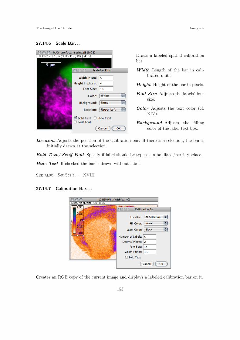
The ImageJ User Guide Analyze !
27.14.6 Scale Bar. . .
Draws a labeled spatial calibrationbar.
Width Length of the bar in cali-brated units.
Height Height of the bar in pixels.
Font Size Adjusts the labels’ fontsize.
Color Adjusts the text color (cf.XIV).
Background Adjusts the fillingcolor of the label text box.
Location Adjusts the position of the calibration bar. If there is a selection, the bar isinitially drawn at the selection.
Bold Text / Serif Font Specify if label should be typeset in boldface / serif typeface.
Hide Text If checked the bar is drawn without label.
See also: Set Scale. . . , XVIII
27.14.7 Calibration Bar. . .
Creates an RGB copy of the current image and displays a labeled calibration bar on it.
153

The ImageJ User Guide Analyze !
Location Defines the position of the bar. If there is a selection, the bar is initially drawnat the selection.
Fill Color Defines the bar’s background color.
Label Adjusts the text color.
Number of Labels Adjusts the total number of values displayed.
Decimal Places Adjust the number of decimal places present in the labels.
Font Size Adjusts labels’ font size (labels are drawn bold if Bold Text is checked)
Zoom Scale Zooms the entire calibration bar.
The Calibration Bar Macros can be used to add a calibration bar to a stack or to all theimages and stacks in a folder.
See also: Calibrate. . . , XVIII
154

The ImageJ User Guide Plugins !
28 Plugins !
28.1 Macros !
This submenu contains commands for installing, running and recording macros, as wellas any macro commands added by Plugins !Macros ! Install. . . Macros contained in a filenamed StartupMacros.txt, in the macros folder, are automatically added to this submenuwhen ImageJ starts up.
28.1.1 Install. . .Improvedin IJ 1.44
Adds one or more macros contained in a file to the bottom of this submenu. To installa set of macros, and at the same time view their source code, open the macro file withFile !Open and use The ImageJ Editor’s Macros ! Install Macros command. Macros in thefile ImageJ/macros/StartupMacros.txt are automatically installed when ImageJ startsup. Similarly, with ImageJ 1.44f and later, newly opened macro sets with two or moremacros are also automatically installed in this menu.
28.1.2 Run. . .
Loads and runs a macro without opening it in The ImageJ Editor. To run a macro,and at the same time view its source code, open it with File !Open and use the editor’sMacros !Run Macro command.
28.1.3 Startup Macros. . .
Opens ImageJ/macros/StartupMacros.txt. The same file can be opened by holding Shift
while selecting Startup Macros from the drop-down menu.
28.1.4 Record. . .
Opens the ImageJ command recorder. To create a macro, open the recorder, use oneor more ImageJ commands, then click Create. When the recorder is open, each menucommand you use generates a macro run() function call. The run() function has oneor two string arguments. The first is the command name. The optional second argumentcontains dialog box parameters. Examples:
– Create a rectangular, oval or line selection and the recorder will generate a make-Rectangle(), makeOval() or makeLine() function call.
– Click on Auto or Set in the Image !Adjust !Threshold. . . [T] window to generate asetThresold() call, and on Reset to generate a resetThresold() call.
155

The ImageJ User Guide Plugins !
– Select an image from the Window menu to generate a selectWindow() call.
– Click in the Image !Color !Color Picker. . . [K] window to generate setForeground-Color() and setBackgroundColor() calls.
Note that you can interact with the recorder window by deleting or commenting lines ofcode or pasting text from The ImageJ Editor. This may be specially useful when writingyour own macros or to generate simple ‘Session Logs’. In this case, you would start theRecorder and let ImageJ keep track of the performed actions by generating macro code.
See also: The ImageJ Editor, Extending ImageJ, The ImageJ Macro Language — Pro-grammer’s Reference Guide
28.2 Shortcuts !
This submenu contains commands for creating keyboard shortcuts and for installing andremoving plugins.
28.2.1 List Shortcuts. . .
This command generates a table with the ImageJ keyboardshortcuts in one column and the commands they call in an-other. Commands prefixed by ‘ * ’ refer to shortcuts createdwith Create Shortcuts. . . Commands prefixed by ‘ ^ ’ referto installed macros (listed in Plugins !Macros ! submenu) andoverride default ImageJ hot-keys.
Note that, as mentioned previously, you do not have to holddown Ctrl to use a keyboard shortcut. E.g., to open animage press O (File !Open. . . ).
See also: Keyboard Shortcuts, Create Shortcuts. . .
156

The ImageJ User Guide Plugins !
28.2.2 Create Shortcuts. . .
Assigns a keyboard shortcut to an ImageJ menucommand and lists the shortcut in the Shortcutssubmenu.
Select the command from the popup menu andenter the shortcut in the text field. A shortcutcan be a lower or uppercase letter or ‘F1’ through‘F12’. Use Plugins !Utilities ! List Shortcuts. . . to geta list of shortcuts that are already being used.
28.2.3 Install Plugin. . .
Installs a plugin in a user-specified submenu.Plugins with a showAbout() method are alsoautomatically added to the Help !About Plugins !submenu.
Use the first popup menu to select the pluginand the second to select the submenu it is toinstalled in. The command must be di"erentfrom any existing ImageJ command. Shortcut(optional) must be a single letter or ‘F1’ through‘F12’. Argument (optional) is the string thatwill passed to the plugin’s run method.
28.2.4 Remove. . .
Removes commands added to the Shortcuts submenu by Create Shortcuts. . . Also re-moves commands added by Install Plugin. . . and removes plugins installed in the Pluginsmenu. The menus are not updated until ImageJ is restarted.
157

The ImageJ User Guide Plugins !
28.3 Utilities !
28.3.1 Control Panel. . . [U]Improvedin IJ 1.44
This command [33] opens a window containingImageJ commands in a hierarchical tree structure.Click on a leaf node to launch the correspondingImageJ command (or plugin). Double click on atree branch node (folder) to expand or collapseit. Click and drag on a tree branch node (folder)to display its descendants in a separate (child)window. In a child window, click on ‘Show Parent’to re-open the parent window.
See also: Command Finder
28.3.2 ImageJ Properties. . .
This command displays various ImageJ properties (Java version, OS name and version,path separator, location of directories, screen size, etc.) in a text window. Holding Altlists all Java properties
See also: Status bar, Help !About ImageJ. . .
28.3.3 Threads. . .
This command lists, in a text window, the currently running threads and their priorities.
28.3.4 Benchmark
Runs 62 image processing operations on the current image and displays the elapsed timein the ImageJ status bar. Additional benchmarks, test results, and source code areavailable in the Benchmarks package of plugins.
See also: FAQ’s on the ImageJ Documentation Wiki
28.3.5 Reset. . .
Use this command to unlock a locked Image, or toreclaim memory used by the clipboard and undobu"ers (cf. Undo and Redo).
158

The ImageJ User Guide Plugins !
28.3.6 Monitor Memory. . .
Displays a continuously updated graph of ImageJ’s memoryutilization, which can be useful for detecting memory leaks.Ideally you should be able to open several images, processthem, close them, and the amount of memory used will bethe same as when you started.
Clicking on ImageJ’s status bar, which forces the Java garbage collector run, may helpreclaim unused memory (cf. Status bar).
Starting the memory monitor holding down Alt will have it use a 640#480 window thatsimulates how a frame grabber plugin would work
28.3.7 Search. . .
Described in Finding Commands.
28.3.8 Capture Screen [g]
Copies the screen to an RGB image and displays that image a new window. HoldingCtrl Shift G will capture the screen while a modal dialog box is active if the dialog isbased on ImageJ’s GenericDialog class.
28.3.9 Capture Image
Copies a WYSIWYG version of active image to an RGB image and displays that imagea new window.
See also: Flatten [F]
28.3.10 Find Commands. . . [l]
Described in Command Finder.
28.4 New !
This submenu contains commands opening editor windows that can be used to edit andrun macros, scripts and plugins. It also has a command that opens a text window of aspecified size and a command that opens a table that macros can write to. The editorwindows opened by Plugin, Plugin Filter and Plugin Frame contain prototype Java codefor the three types of plugins supported by ImageJ.
See also: The ImageJ Editor, Extending ImageJ
159

The ImageJ User Guide Plugins !
28.4.1 Macro
Opens a blank editor window with the title ‘Macro.txt’.
See also: Macros, The ImageJ Editor, Text Window. . . , File !New !Text Window [N]
28.4.2 JavaScript
Opens a blank editor window with the title ‘Script.js’.
See also: Scripts, The ImageJ Editor
28.4.3 Plugin
Opens an editor window containing a prototype plugin that implements the PlugIninterface. Plugins of this type open, capture or generate images. The prototype displays"Hello world!" in the ImageJ window. Press Ctrl R (File !Run Macro) to compileand run it. Note that the name you choose for the plugin should include at least oneunderscore. Another example is the Step Maker plugin.
28.4.4 Plugin Filter
Opens an editor window containing a prototype plugin that implements the PlugInFilterinterface. Plugins of this type process the active image. The prototype inverts the activeimage twice. Another example is the Image Inverter.
28.4.5 Plugin Frame
Opens an editor window containing a prototype plugin that extends the PlugInFrameclass. Plugins of this type displays a window containing controls such as buttons andsliders. The prototype opens a window containing a text area. Another example is theIP Demo plugin.
28.4.6 Text Window. . .
Opens a text window of a specified size that macros can writeto. PrintToTextWindow, Clock and ProgressBar are exam-ples of macros that write to a text window.
See also: Plugins !New !Macro, File !New !Text Window[N]
160

The ImageJ User Guide Plugins !
28.4.7 Table. . .
Opens a blank table, similar to the Results table, that macroscan write to. SineCosineTable2 (http://imagej.nih.gov/ij/macros/SineCosineTable2.txt) is an example of such a macro.
See also: Plugins !New !Text Window. . .
28.5 Compile and Run. . .Improvedin IJ 1.44
Compiles and runs a plugin. Runs a plugin if the name of the selected file ends in.class. Requires that ImageJ be running on a Java Virtual Machine that includes thejavac compiler, which is contained in the Tools.jar archive. Tools.jar is included withthe Windows and Linux versions of ImageJ bundled with Java, and it is pre-installed onMac OS X. Troubleshooting information can be found under ‘Compiling Plugins’ in theLinux and Windows release notes.
The Edit !Options !Compiler. . . command can be used to configure the javac com-piler. Since ImageJ 1.44c and later, Compile and Run. . . adds the Bio-Formats plugin(loci_tools.jar) to the Java compiler’s classpath.
161

The ImageJ User Guide Window
29 Window
This menu contains four commands plus a list of open ImageJ windows. The currentlyactive image will have a checkmark next to its name. To activate a window, pull downthis menu and select the window by name.
29.1 Show All [ ] ]
Makes all the windows associated with ImageJ visible.
29.2 Put Behind [tab]
Displays the next open image. Repeatedly press the tab key to cycle through all openimages. Note that pressing Enter on any image will bring the ImageJ window to theforeground.
See also: I
29.3 Cascade
Moves all open images to the left side of the screen, slightly o"set from each other, anddisplayed in the order they are listed at the bottom of this menu.
29.4 Tile
Shrinks all open image windows and repositions them to fit on the screen without over-lapping.
162

The ImageJ User Guide Help !
30 Help !
Many of the commands in this menu use ImageJ’s BrowserLauncher to open a Webpage using the user’s default browser. On Linux, BrowserLauncher looks for ’netscape’,’firefox’, ’konqueror’, ’mozilla’, ’opera’, ’epiphany’ or ’lynx’ and uses the first one it finds.
30.1 ImageJ Website. . .
Opens the ImageJ home page.
30.2 ImageJ News. . .
Opens the News section of the ImageJ website.
30.3 Documentation. . .
Opens the Documentation section of the ImageJ website.
30.4 Installation. . .
Opens the Installation section of the ImageJ website specifically dedicated to the OS inwhich ImageJ is running, i.e either Linux, Mac OS 9, Mac OS X or Windows. Worthreading are the sections Known Problems and Troubleshooting.
30.5 Search Website. . .
Opens the Search page on the ImageJ website. Use this page to find plugins, macros, ormessages that have been posted to the ImageJ mailing list.
30.6 List Archives. . .
Opens the ImageJ Interest Group page on the NIH LISTSERV facility. Here you cansearch the mailing list archives, post a message to the list, join or leave the list, or updateoptions.
30.7 Dev. Resources. . .
Opens the Developer Resources section of the ImageJ website.
163

The ImageJ User Guide Help !
30.8 Plugins. . .
Opens the Plugins page on the ImageJ website, which lists more than 500 ImageJ plugins.
30.9 Macros. . .
Opens the macros directory on the ImageJ website, which contains more than 400 ImageJmacros.
30.10 Macro Functions. . .
Opens the Macro Functions reference page, an indispensable guide to the built in func-tions that can be called from the ImageJ macro language.
See also: Macros
30.11 Update ImageJ. . .
Upgrades ImageJ to the latest ij.jar at http://imagej.nih.gov/ij/upgrade/, or downgrades to one of the ear-lier versions at http://imagej.nih.gov/ij/download/jars/. Select daily build from the drop-down menuand ImageJ will be upgraded to the latest daily buildat http://imagej.nih.gov/ij/ij.jar.
See also: Maintaining ImageJ
30.12 Refresh MenusChangedin IJ 1.44
Use this command to update ImageJ’s menus after adding (or removing) plugins ormacros to the plugins folder. Prior to ImageJ 1.44b this command was named ‘UpdateMenus’.
30.13 About Plugins !
This submenu displays information about some of the plugins in the ImageJ pluginsfolder. To be included in this submenu, a plugin must be packaged as a JAR file. Thereis an example at rsb.info.nih.gov/ij/plugins/jar-demo.html.
164
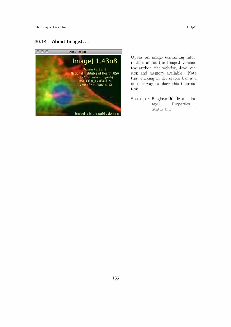
The ImageJ User Guide Help !
30.14 About ImageJ. . .
Opens an image containing infor-mation about the ImageJ version,the author, the website, Java ver-sion and memory available. Notethat clicking in the status bar is aquicker way to show this informa-tion.
See also: Plugins !Utilities ! Im-ageJ Properties. . . ,Status bar
165

Part VI
Keyboard Shortcuts
The following table summarizes the keyboard shortcuts built into ImageJ. You can createadditional shortcuts, or override built-in ones, by creating simple macros and adding themto the StartupMacros.txt. You can also assign a function key to a menu command usingPlugins ! Shortcuts !Create Shortcuts. . . .
Except when using the text tool, you do not need to hold down the control key to use akeyboard shortcut (cf. Edit !Options !Misc. . . ).
A similar list can be obtained using ImageJ Plugins ! Shortcuts ! List Shortcuts. . . com-mand. This table is also available at http://imagej.nih.gov/ij/docs/shortcuts.html.
See also: Shortcuts and Modifier Keys, Finding Commands, Macro Tools
List of ImageJ 1.44 built-in shortcuts. This table can be obtained within ImageJ using thePlugins ! Shortcuts ! List Shortcuts. . . command.
Command /Operation Shortcut Description
File !New ! Image. . . [n] N Create new image or stackNew !Text Window [N] Shift N Create new text windowNew ! System Clipboard [V] Shift V Create image from system clipboardOpen. . . O Open file (any format recognized by ImageJ)Open Next [O] Shift O Open next image in folderOpen Samples !Blobs (25K) Shift B Opens the Blobs.gif example imageClose [w] W Close the active windowSave [s] S Save active image in Ti! formatRevert [r] R Revert to saved version of imagePrint. . . [p] P Print active image
Edit !Undo [z] Z Undo last operationCut [x] X Copy selection to internal clipboard and clearCopy [c] C Copy selection to internal clipboardPaste [v] V Paste contents of internal clipboardClear Backspace Erase selection to background colorFill [f] F Fill selection in foreground colorDraw [d] D Draw selectionInvert [I] Shift I Invert image or selectionSelection ! Select All [a] A Select entire image

The ImageJ User Guide
List of ImageJ 1.44 built-in shortcuts. This table can be obtained within ImageJ using thePlugins ! Shortcuts ! List Shortcuts. . . command.
Command /Operation Shortcut Description
Selection ! Select None [A] Shift A Remove selectionSelection !Restore Selection [E] Shift E Restore previous selectionSelection !Properties. . . [y] Y Defines selection propertiesSelection !Add to Manager [t] T Add selection to ROI Manager
Image !Adjust !Brightness/Contrast. . . [C] Shift C Adjust brightness and contrastAdjust !Threshold. . . [T] Shift T Adjust threshold levelsShow Info. . . [i] I Display information about active imageProperties. . . [P] Shift P Display image propertiesColor !Color Picker. . . [K] Shift K Open Color PickerStacks !Next Slice [>] > or $ Go to next stack sliceStacks !Previous Slice [<] < or % Go to previous stack sliceStacks !Reslice. . . [/] / Reslice stackStacks !Orthogonal Views [H] Shift H Toggle orthogonal view displayStacks !Tools ! Start Animation [\] \ Start/stop stack animationHyperstacks !Channels. . . [Z] Shift Z Open the ‘Channels’ toolHyperstacks > or $ Next hyperstack channelHyperstacks < or % Previous hyperstack channelHyperstacks Ctrl > Next hyperstack sliceHyperstacks Ctrl < Previous hyperstack sliceHyperstacks Alt > Next hyperstack frameHyperstacks Alt < Previous hyperstack frameCrop [X] Shift X Crop active image or selectionDuplicate. . . [D] Shift D Duplicate active image or selectionScale. . . [E] E Scale image or selectionZoom ! In [+] + or " Make image largerZoom !Out ["] ! or # Make image smallerZoom !Original Scale [4] 4 Revert to original zoom levelZoom !View 100% [5] 5 Zoom to 1:1
Process !Smooth [S] Shift S 3#3 unweighted smoothingRepeat Command [R] Shift R Repeat previous command
Analyze !Measure. . . [m] M Display statistics of active image / selectionHistogram [h] H Display histogram of active image / selectionPlot Profile [k] K Display density profile plot of active selectionGels ! Select First Lane 1 Select first gel lane
167

The ImageJ User Guide Alt Key Modifications
List of ImageJ 1.44 built-in shortcuts. This table can be obtained within ImageJ using thePlugins ! Shortcuts ! List Shortcuts. . . command.
Command /Operation Shortcut Description
Gels ! Select Next Lane 2 Select next gel laneGels !Plot Lanes 3 Plot gel lanes
Plugins !Utilities !Control Panel. . . [U] Shift U Open Control PanelUtilities !Capture Screen [g] Shift G Grab screenshotUtilities !Find Commands. . . [l] L List, find and launch commands
Window !
Show All ] Make all windows visiblePut Behind Tab Switch to next image windowImageJ Enter Bring ImageJ window to front
31 Alt Key Modifications
File !Open Next Open Previous
File !Revert Don’t show dialog
Edit !Copy Copy to system clipboard
Image !Color !Split Channels Keep original image
Image ! Stacks !Add Slice Insert before current slice
Image ! Stacks !Next Slice Skip nine slices
Image ! Stacks !Previous Slice Skip nine slices
Image ! Stacks ! Start Animation Show options dialog
Image !Duplicate Don’t show dialog
Image !Overlay !Add Selection Don’t show dialog
Process !Equalize Do classic histogram equalization
Analyze !Histogram Show dialog
Analyze !Plot Profile For rectangular selections, generate row average plot
Analyze !Plot Profile For wide straight lines, display rotated contents
Analyze !Gels ! Select First Lane Assume lanes are horizontal
Analyze !Tools !Analyze Line Graph Show intermediate image
Analyze !Tools !Roi Manager(Add) Name and add selection
Plugins !Utilities ! ImageJ Properties List all Java properties
168

The ImageJ User Guide Space Bar
Plugins !Utilities !Monitor Memory Simulate 640#480 frame grabber
Any user plugin Load using new class loader
Area selection tools Subtract this selection from the previous one
Rectangle and Oval selection tools Current aspect ratio is maintained while resizing
Polygon selection tool Alt-click on a node to delete it
Straight line tool Keeps the line length fixed while moving either end of the line. Forces thetwo points that define the line to have integer coordinate values when creating a line on azoomed image
Segmented line tool Alt-click on a node to delete it
Point tool Alt-click on a point to delete it
Color picker tool Alt-click to ‘pick-up’ background color
All tools Show location and size in pixels
32 Shift Key Modifications
Image !Adjust !Threshold Adjusting Min also adjusts Max
Image !Adjust !Brightness/Contrast Apply adjustments to all channels of a composite image
Installed Macros and Scripts Open instead of run
Rectangle and Oval selection tools Forces 1:1 aspect ratio
Area selection tool Add this selection to previous one
Polygon selection tool Shift-click on a node to duplicate it
Straight line tool Forces line to be horizontal or vertical
Segmented line selection tool Shift-click on a node to duplicate it
Point selection tool Shift-click to add a point
33 Ctrl Key (or Cmd Key on Macs) Modifications
Rectangle and Oval selection tools (With Alt) Current aspect ratio is maintained whileresizing
Rectangle and Oval selection tools Selection is resized around the center
Straight line tool Rotate/resize the line about its center
34 Space Bar
Any Tool Switch to the hand tool
169

The ImageJ User Guide Keyboard Shortcuts for ImageJ Tools
35 Arrow Keys
Moving Selections The four arrow keys move selection outlines one pixel at a time
Resizing Selections Rectangular and oval selections are resized by holding Alt while usingthe arrow keys
Stacks Navigation The % and $ keys substitute for < and > for moving through a stack.If there is a selection, you must also hold Shift
Hyperstacks Navigation The % and $ keys change the channel. Hold Ctrl to movethrough the slices and Alt to move through the frames
Zooming The " and # keys zoom the image in and out. If there is a selection, you mustalso hold either Shift or Ctrl
36 Keyboard Shortcuts for ImageJ Tools
Keyboard shortcuts cannot be used directly to activate tools in the ImageJ toolbar (withthe exception of the Magnifying Glass and the Scrolling Tool). However, shortcuts canbe assigned to macros that use the setTool() function. Once copied to the to theImageJ/macros/StartupMacros.txt file ImageJ will automatically install them at start-up.
The set of macros listed below (taken from the Rename and Save ROI Sets toolset)exemplify the use of the setTool() function by assigning the numeric keys 1–4 to thefirst four area selection Tools. The macro ‘Refine selection’ activates temporarily thebrush selection tool when 5 is pressed. Once the mouse is released the previouslyselected tool is restored.
Listing 7 Assigning Keyboard Shortcuts to ImageJ Tools1 /* This set of macros exemplifies how to use the setTool () function to
assign hotkeys to ImageJ tools. */23 macro "Rectangle [1]" {setTool("rectangle");}4 macro "Ellipse [2]" {setTool("elliptical");}5 macro "Polygon [3]" {setTool("polygon");}6 macro "Freehand [4]" {setTool("freehand");}7 macro "Refine Area Selection [5]" {8 tool = IJ.getToolName;9 setTool("brush");
10 while (true) {11 getCursorLoc(x, y, z, flags);12 i f (flags&16!=0){setTool(tool); exit;}13 }14 }
This approach, however, requires the user to memorize as many shortcuts as the numberof tools in the toolbar. In addition, it may be di#cult to assign so many hot-keys without
170

The ImageJ User Guide Keyboard Shortcuts for ImageJ Tools
conflicting with previously defined ones (see List Shortcuts. . . ). Probably a more e#cientway to control the toolbar using the keyboard is to create macros that can cycle throughall the tools in the ImageJ toolbar. The next example demonstrates such an approach.It is composed of two macros activated by F1 and F2 that iterate through the toolbaritems from left to right (forward cycle) and right to left (reverse cycle).
Listing 8 Cycling Through ImageJ Tools Using Keyboard Shortcuts1 /* These two macros loop through the tools listed in an array using "F1"
and "F2" as keyboard shortcuts (forward and reverse cycling). */23 var tIndx= 0;4 var tools= newArray("rectangle", "roundrect", "oval", "ellipse", "brush",
"polygon", "freehand", "line","freeline","polyline", "arrow", "wand","dropper", "angle", "point","multipoint", "text");
56 macro "Cycle Tools Fwd [F1]"{7 setTool(tools[tIndx]);8 tIndx++;9 i f (tIndx==tools.length)
10 tIndx = 0;11 }1213 macro "Cycle Tools Rwd [F2]" {14 tIndx--;15 i f (tIndx<0)16 tIndx = tools.length -1;17 setTool(tools[tIndx]);18 }
171

Credits
[C1] The Command Finder was written by Mark Longair.
[C2] The macro editor’s Function Finder (Macros !Find Functions...) was written by JérômeMutterer.
[C3] The Elliptical Selection Tool was contributed by Norbert Vischer.
[C4] The Brush Selection Tool is based on the ROI Brush Tool plugin from Tom Larkworthyand Johannes Schindelin.
[C5] Michael Schmid, added 4–connected and 8–connected tracing with tolerance to the WandTool.
[C6] The File ! Import !Results. . . command is based on Jérôme Mutterer’s Im-port_Results_Table macro.
[C7] Michael Schmid contributed improvements to the AVI reader and AVI writer plugins.
[C8] Karen Collins contributed improvements to the FITS_Writer (File ! Save As !FITS. . .command).
[C9] The Edit ! Selection !Fit Circle command, based on a MATLAB script by Nikolai Cher-nov (http://www.math.uab.edu/~chernov/cl/MATLABcircle.html), was contributed byMichael Doube and Ved Sharma
[C10] The Edit ! Selection !Create Selection command is based on the Threshold_To_Selectionplugin written by Johannes Schindelin.
[C11] The Color Picker (Image !Color !Color Picker. . . [K]) was written by Gali Baler, a 2003–2004 intern from Bethesda-Chevy Chase High School.
[C12] The 16 di!erent thresholding methods available in the Image !Adjust !Threshold. . . [T]tool were implemented by Gabriel Landini.
[C13] Michael Schmid contributed improvements to the downsizing kernel used by Image !Adjust ! Size. . . and Image ! Scale. . . [E] as well as undo support for Image ! Scale. . . [E].
[C14] The Image !Adjust !Color Threshold. . . command implements Gabriel Landini’s Thresh-old Colour plugin.
[C15] The Reslice and the ZProject plugin (Image ! Stacks !Reslice. . . [/] and Z Project. . . com-mands) were contributed by Patrick Kelly and Harvey Karten of the University of Cali-fornia, San Diego.
[C16] The Image ! Stacks !Orthogonal Views [H] command is based on Dimiter Prodanov’sStackSlicer plugin and Albert Cardona’s Updater class. Michael Doube added supportfor XZ and YZ view control as well as mouse wheel control.
[C17] The Image ! Stacks ! 3D Project. . . was written by Michael Castle and Janice Keller ofthe University of Michigan Mental Health Research Institute (MHRI). Bill Mohler addedsuport for hyperstacks and 16/32–bit images in IJ 1.44m.
[C18] The Image ! Stacks !Tools !Make Substack. . . command is based on the Substack Makerplugin by Anthony Padua, Daniel Barboriak and Ved Sharma.
[C19] The Image !Hyperstacks !Reduce Dimensionality. . . command is based on Jérôme Mut-terer’s Reduce HyperStack macro.
172

[C20] The Image !Zoom ! Set. . . command is based on Albert Cardona’s Zoom Exact plugin.
[C21] The Process !Find Maxima. . . command is based on a plugin contributed by MichaelSchmid.
[C22] The equalization code implemented in Process !Enhance Contrast was contributed byRichard Kirk.
[C23] The Process !Math !Macro. . . command is modeled after Ulf Dittmer’s Expression plu-gin.
[C24] The Process !FFT !Bandpass Filter. . . is a built in version of Joachim Walter’s FFT Filterplugin.
[C25] The Process !Binary !Fill Holes algorithm was contributed by Gabriel Landini.
[C26] The faster and more accurate version of Process !Filters !Gaussian Blur. . . implementedin ImageJ 1.38r and later was contributed by Michael Schmid.
[C27] The NonBlockingGenericDialog.class used by the Process !Batch !Macro. . . com-mand was added by Johannes Schindelin.
[C28] The Analyze !Distribution. . . command was written by Gabriel Landini.
[C29] The scaled color bar implemented in Analyze !Histogram [h] was contributed by BobDougherty.
[C30] The Rodboard and Gaussian functions implemented in (Analyze !Tools !Curve Fitting. . . )were contributed by David Rodbard (NIH) and Stefan Wörz (DKFZ), respectively.
[C31] The ROI Manager(XOR) command (Analyze !Tools !ROI Manager. . . ) was added byJohannes Schindelin.
[C32] The ROI Manager(Multi Measure) command (Analyze !Tools !ROI Manager. . . ) is basedon Bob Dougherty’s Multi_Measure plugin.
[C33] The Control Panel (Plugins !Utilities !Control Panel. . . [U]) was written by Cezar M.Tigare.
[C34] Other additions, improvements and bug fixes have been contributed by:Albert Cardona, Adrian Daerr, Alden Dima, Andreas Maier, Barry DeZonia, Chris-tian Moll, Dimiter Prodanov, Divakar Ramachandran, Duncan Mak, Erik Meijering,Frederic Hessman, Gabriel Landini, Jan Funke, Jay Unruh, Joachim Wesner, JohannesHermen, Johannes Schindelin, Juan Grande, Julian Cooper, Kai Uwe Barthel, KarenCollins, Kevin Moll, Mark Longair, Matthew Smith, Michael Doube, Michael Ellis,Michael Schmid, Nico Stuurman, Norbert Vischer, Olaf Freyer, Reinhard Mayr, RobertDougherty, Shannon Stewman, Stephan Saalfeld, Stefan Starke, Tiago Ferreira, TsengQingzong, Ulf Dittmer, Uwe Walschus, Ved Sharma, Wilhelm Burger.
[C35] Macro Toolsets distributed with ImageJ have been contributed by:Gilles Carpentier (Arrow Labelling Tools.txt, Scale Bar Tools for Microscopes.txt),Jérôme Mutterer (Example Icons.txt, Magic Montage.txt), Tiago Ferreira (Toolset Cre-ator.txt).
173

ImageJ Related PublicationsThe following references are a small sample of the bibliography directly related to ImageJ, thestandard in scientific image analysis. These publications include: 1) technical articles and booksdescribing routines implemented in ImageJ, 2) research articles that have made extensive useof ImageJ as a scientific tool or 3) reviews that discuss ImageJ pertinently. This list appears inchronological order rather than alphabetical and is particularly biased towards the life sciences.
[1] Michael Doube, Michal M Klosowski, Ignacio Arganda-Carreras, Fabrice P Cordelieres,Robert P Dougherty, Jonathan S Jackson, Benjamin Schmid, John R Hutchinson, andSandra J Shefelbine. BoneJ: Free and extensible bone image analysis in ImageJ. Bone,47(6):1076–9, Dec 2010.
[2] Arthur Edelstein, Nenad Amodaj, Karl Hoover, Ron Vale, and Nico Stuurman. Computercontrol of microscopes using µManager. Curr Protoc Mol Biol, Chapter 14:Unit14.20, Oct2010.
[3] Thomas Walter, David W Shattuck, Richard Baldock, Mark E Bastin, Anne E Carpenter,Suzanne Duce, Jan Ellenberg, Adam Fraser, Nicholas Hamilton, Steve Pieper, Mark ARagan, Jurgen E Schneider, Pavel Tomancak, and Jean-Karim Hériché. Visualization ofimage data from cells to organisms. Nature Methods, 7(3 Suppl):S26–41, Mar 2010.
[4] Sascha Meyer Dos Santos, Ute Klinkhardt, Reinhard Schneppenheim, and SebastianHarder. Using ImageJ for the quantitative analysis of flow-based adhesion assays in real-time under physiologic flow conditions. Platelets, 21(1):60–6, Feb 2010.
[5] Albert Cardona, Stephan Saalfeld, Stephan Preibisch, Benjamin Schmid, Anchi Cheng, JimPulokas, Pavel Tomancak, and Volker Hartenstein. An integrated micro- and macroar-chitectural analysis of the Drosophila brain by computer-assisted serial section electronmicroscopy. PLoS Biol, 8(10), Jan 2010.
[6] Adam S Green, Paul R Ohmann, Nick E Leininger, and James A Kavanaugh. PolarizationImaging and Insect Vision. The Physics Teacher, 48:17, Jan 2010. (c) 2010: AmericanInstitute of Physics.
[7] E Iannuccelli, F Mompart, J Gellin, Y Lahbib-Mansais, M Yerle, and T Boudier. NEMO: atool for analyzing gene and chromosome territory distributions from 3D-FISH experiments.Bioinformatics (Oxford, England), Jan 2010.
[8] Christof Karmonik, Michele York, Robert Grossman, Ekta Kakkar, Krutina Patel, HaniHaykal, and David King. An image analysis pipeline for the semi-automated analysis ofclinical fMRI images based on freely available software. Computers in biology and medicine,Jan 2010.
[9] Benjamin Schmid, Johannes Schindelin, Albert Cardona, Mark Longair, and MartinHeisenberg. A high-level 3D visualization API for Java and ImageJ. BMC Bioinformatics2010 11:274, 11:274, Jan 2010.
[10] German Kilimnik, Abraham Kim, Junghyo Jo, Kevin Miller, and Manami Hara. Quan-tification of pancreatic islet distribution in situ in mice. Am J Physiol Endocrinol Metab,297(6):E1331–8, Dec 2009.
[11] Atsuko Kobayashi, Takumi Fujigaya, Masayuki Itoh, Takahisa Taguchi, and HiroshiTakano. Technical note: a tool for determining rotational tilt axis with or without fiducialmarkers. Ultramicroscopy, 110(1):1–6, Dec 2009.
174

[12] Philippe Mailly, Suzanne N Haber, Henk J Groenewegen, and Jean-Michel Deniau. A 3Dmulti-modal and multi-dimensional digital brain model as a framework for data sharing.J Neurosci Methods, Dec 2009.
[13] Richard L Mort. Quantitative analysis of patch patterns in mosaic tissues with ClonalToolssoftware. J Anat, 215(6):698–704, Dec 2009.
[14] T Vrekoussis, V Chaniotis, I Navrozoglou, V Dousias, K Pavlakis, E N Stathopoulos, andO Zoras. Image analysis of breast cancer immunohistochemistry-stained sections usingImageJ: an RGB-based model. Anticancer Res, 29(12):4995–8, Dec 2009.
[15] Emel Bulut and Bünyamin Sahin. A new method of assessing the size of mandibular cystson orthopantomograms: projection area fraction. J Craniofac Surg, 20(6):2020–3, Nov2009.
[16] J Hegyi, V Hegyi, G Messer, P Arenberger, T Ruzicka, and C Berking. Confocal laser-scanning capillaroscopy: a novel approach to the analysis of skin capillaries in vivo. SkinRes Technol, 15(4):476–81, Nov 2009.
[17] Jason R Swedlow and Kevin W Eliceiri. Open source bioimage informatics for cell biology.Trends in Cell Biology, 19(11):656–60, Nov 2009.
[18] Clayton M Costa and Suann Yang. Counting pollen grains using readily available, freeimage processing and analysis software. Ann Bot, 104(5):1005–10, Oct 2009.
[19] Nicola Goodall, Lilian Kisiswa, Ankush Prashar, Stuart Faulkner, Pawe" Tokarczuk, KrishSingh, Jonathan T Erichsen, Jez Guggenheim, Willi Halfter, and Michael A Wride. 3-Dimensional modelling of chick embryo eye development and growth using high resolutionmagnetic resonance imaging. Exp Eye Res, 89(4):511–21, Oct 2009.
[20] Fathima Shihana, Dhammika Menike Dissanayake, Nicholas Allan Buckley, and An-drew Hamilton Dawson. A Simple Quantitative Bedside Test to Determine Methemoglobin.Ann Emerg Med, Oct 2009.
[21] János Roszik, Duarte Lisboa, János Szöllosi, and György Vereb. Evaluation of intensity-based ratiometric FRET in image cytometry–approaches and a software solution. Cytom-etry A, 75(9):761–7, Sep 2009.
[22] Edmund Y Tong, Geo!rey C Collins, April E Greene-Colozzi, Julia L Chen, Philip DManos, Kyle M Judkins, Joseph A Lee, Michael J Ophir, Farrah M Laliberte, and Timo-thy J Levesque. Motion-based angiogenesis analysis: a simple method to quantify bloodvessel growth. Zebrafish, 6(3):239–43, Sep 2009.
[23] Stephan Saalfeld, Albert Cardona, Volker Hartenstein, and Pavel Tomancák. CATMAID:collaborative annotation toolkit for massive amounts of image data. Bioinformatics (Ox-ford, England), 25(15):1984–6, Aug 2009.
[24] Atsuki Fukushima and Tsutomu Tomita. Image analyses of the kinetic changes of conjunc-tival hyperemia in histamine-induced conjunctivitis in Guinea pigs. Cornea, 28(6):694–8,Jul 2009.
[25] David J Barry, Cecilia Chan, and Gwilym A Williams. Morphological quantification of fil-amentous fungal development using membrane immobilization and automatic image anal-ysis. J Ind Microbiol Biotechnol, 36(6):787–800, Jun 2009.
175

[26] Stephan Hegge, Mikhail Kudryashev, Ashley Smith, and Friedrich Frischknecht. Auto-mated classification of Plasmodium sporozoite movement patterns reveals a shift towardsproductive motility during salivary gland infection. Biotechnol J, 4(6):903–13, Jun 2009.
[27] Richard M Lindley, Daniel B Hawcutt, M Gwen Connell, David H Edgar, and Simon EKenny. Properties of secondary and tertiary human enteric nervous system neurospheres.J Pediatr Surg, 44(6):1249–55; discussion 1255–6, Jun 2009.
[28] Stephan Preibisch, Stephan Saalfeld, and Pavel Tomancak. Globally optimal stitching oftiled 3D microscopic image acquisitions. Bioinformatics (Oxford, England), 25(11):1463–5,Jun 2009.
[29] Delphine S A Beeckman, Geert Meesen, Patrick Van Oostveldt, and Daisy Vanrompay.Digital titration: automated image acquisition and analysis of load and growth of Chlamy-dophila psittaci. Microsc. Res. Tech., 72(5):398–402, May 2009.
[30] A J Hand, T Sun, D C Barber, D R Hose, and S MacNeil. Automated tracking of migratingcells in phase-contrast video microscopy sequences using image registration. Journal ofmicroscopy, 234(1):62–79, Apr 2009.
[31] Tal Shprung and Illana Gozes. A novel method for analyzing mitochondrial movement:inhibition by paclitaxel in a pheochromocytoma cell model. J Mol Neurosci, 37(3):254–62,Mar 2009.
[32] Evan C Crawford and James K Mortensen. An ImageJ plugin for the rapid morphologicalcharacterization of separated particles and an initial application to placer gold analysis.Computers & Geosciences, 35:347, Feb 2009.
[33] Manuel G Forero, Jenny A Pennack, Anabel R Learte, and Alicia Hidalgo. DeadEasyCaspase: Automatic Counting of Apoptotic Cells in Drosophila. Plos One, 4(5):e5441, Jan2009.
[34] C Igathinathane, L. O Pordesimo, and W. D Batchelor. Major orthogonal dimensionsmeasurement of food grains by machine vision using ImageJ. Food Res Int, 42(1):76–84,Jan 2009.
[35] Noel Jabbour, Priya D Krishna, James Osborne, and Clark A Rosen. A new approach togeometrical measurements in an animal model of vocal fold scar. J Voice, 23(1):88–94, Jan2009.
[36] Yoonseok Kam, Audrey Karperien, Brandy Weidow, Lourdes Estrada, Alexander R An-derson, and Vito Quaranta. Nest expansion assay: a cancer systems biology approach toin vitro invasion measurements. BMC Res Notes, 2:130, Jan 2009.
[37] H M Macdonald, D M L Cooper, and H A McKay. Anterior-posterior bending strength atthe tibial shaft increases with physical activity in boys: evidence for non-uniform geometricadaptation. Osteoporos Int, 20(1):61–70, Jan 2009.
[38] Peter A McAtee, Ian C Hallett, Jason W Johnston, and Robert J Scha!er. A rapid methodof fruit cell isolation for cell size and shape measurements. Plant Methods, 5:5, Jan 2009.
[39] Ricardo B Medeiros, Kate J Papenfuss, Brian Hoium, Kristen Coley, Joy Jadrich, Saik-KiaGoh, Anuratha Elayaperumal, Julio E Herrera, Ernesto Resnik, and Hsiao-Tzu Ni. Novelsequential ChIP and simplified basic ChIP protocols for promoter co-occupancy and targetgene identification in human embryonic stem cells. BMC Biotechnol, 9:59, Jan 2009.
176

[40] Christopher A Myrick. A low-cost system for capturing and analyzing the motion of aquaticorganisms. J N Am Benthol Soc, 28(1):101–109, Jan 2009.
[41] Jonathan Popko, Adelaide Fernandes, Dora Brites, and Lorene M Lanier. AutomatedAnalysis of NeuronJ Tracing Data. Cytom Part A, 75A(4):371–376, Jan 2009.
[42] Zhuang Tian, Li Qiang Liu, Chifang Peng, Zhenxing Chen, and Chuanlai Xu. A newdevelopment of measurement of 19-Nortestosterone by combining immunochromatographicstrip assay and ImageJ software. Food Agr Immunol, 20(1):1–10, Jan 2009.
[43] Jun Xu and Dong Chen. Desing and Implementation of the Image Format Batch-Conversion Software Based on ImageJ. Astronomical Research and Technology. Publi-cations of National Astronomical Observatories of China (ISSN 1672-7673), 5:270, Sep2008.
[44] David Hecker, Joachim Kappler, Alexander Glassmann, Karl Schilling, and Wolfgang Alt.Image analysis of time-lapse movies–a precision control guided approach to correct motionartefacts. J Neurosci Methods, 172(1):67–73, Jul 2008.
[45] Dilraj Grewal, Rajeev Jain, Gagandeep Singh Brar, and Satinder Pal Singh Grewal. Pen-tacam tomograms: a novel method for quantification of posterior capsule opacification.Invest Ophthalmol Vis Sci, 49(5):2004–8, May 2008.
[46] Madeline Pool, Joachim Thiemann, Amit Bar-Or, and Alyson E Fournier. NeuriteTracer:a novel ImageJ plugin for automated quantification of neurite outgrowth. J NeurosciMethods, 168(1):134–9, Feb 2008.
[47] Wilhelm Burger and Mark James Burge. Digital image processing: An algorithmic intro-duction using Java. ISBN 978-1-84628-379-6, Springer, Jan 2008.
[48] C Igathinathane, L. O Pordesimo, E. P Columbus, W. D Batchelor, and S. R Methuku.Shape identification and particles size distribution from basic shape parameters using Im-ageJ. Comput Electron Agr, 63(2):168–182, Jan 2008.
[49] Anna Kirilova, Gina Lockwood, M Math, Perry Choi, Neelufer Bana, Masoom A Haider,Kristy K Brock, Cynthia Eccles, and Laura A Dawson. Three-dimensional motion of livertumors using cine-magnetic resonance imaging. Int J Radiat Oncol, 71(4):1189–1195, Jan2008.
[50] Mahdad Noursadeghi, Jhen Tsang, Thomas Haustein, Robert F Miller, Benjamin M Chain,and David R Katz. Quantitative imaging assay for NF-&B nuclear translocation in primaryhuman macrophages. J Immunol Methods, 329(1-2):194–200, Jan 2008.
[51] János Roszik, János Szöllosi, and György Vereb. AccPbFRET: an ImageJ plugin forsemi-automatic, fully corrected analysis of acceptor photobleaching FRET images. BMCBioinformatics, 9:346, Jan 2008.
[52] Ruggero Scorcioni, Susan N Wright, J. Patrick Card, Giorgio A Ascoli, and German Bar-rionuevo. Point analysis in Java applied to histological images of the perforant pathway:A user’s account, Jan 2008.
[53] S Sieuwerts, F. A. M de Bok, E Mols, W. M de Vos, and J. E. T. van Hylckama Vlieg.A simple and fast method for determining colony forming units. Lett Appl Microbiol,47(4):275–278, Jan 2008.
177

[54] Simon A W G Dello, Ronald M van Dam, Jules J G Slangen, Marcel C G van de Poll, MarcH A Bemelmans, Jan Willem W M Greve, Regina G H Beets-Tan, Stephen J Wigmore,and Cornelis H C Dejong. Liver volumetry plug and play: do it yourself with ImageJ.World J Surg, 31(11):2215–21, Nov 2007.
[55] Stéphane Kerner, Daniel Etienne, Jacques Malet, Francis Mora, Virginie Monnet-Corti,and Philippe Bouchard. Root coverage assessment: validity and reproducibility of animage analysis system. J Clin Periodontol, 34(11):969–76, Nov 2007.
[56] Gary Chinga, Per Olav Johnsen, Robert Dougherty, Elisabeth Lunden Berli, and JoachimWalter. Quantification of the 3D microstructure of SC surfaces. Journal of microscopy,227(Pt 3):254–65, Sep 2007.
[57] Eckard Picht, Aleksey V Zima, Lothar A Blatter, and Donald M Bers. SparkMaster:automated calcium spark analysis with ImageJ. Am J Physiol, Cell Physiol, 293(3):C1073–81, Sep 2007.
[58] A Solé, J Mas, and I Esteve. A new method based on image analysis for determin-ing cyanobacterial biomass by CLSM in stratified benthic sediments. Ultramicroscopy,107(8):669–73, Aug 2007.
[59] David Stepensky. FRETcalc plugin for calculation of FRET in non-continuous intracellularcompartments. Biochem. Biophys. Res. Commun., 359(3):752–8, Aug 2007.
[60] Tony J Collins. ImageJ for microscopy. BioTechniques, 43(1 Suppl):25–30, Jul 2007.
[61] Martha L Narro, Fan Yang, Robert Kraft, Carola Wenk, Alon Efrat, and Linda L Restifo.NeuronMetrics: software for semi-automated processing of cultured neuron images. BrainRes., 1138:57–75, Mar 2007.
[62] Kevin M Schartz, Kevin S Berbaum, Robert T Caldwell, and Mark T Madsen. Work-stationJ: workstation emulation software for medical image perception and technologyevaluation research. Medical Imaging 2007: Image Perception, 6515:49, Mar 2007.
[63] Brian A Irving, Judy Y Weltman, David W Brock, Christopher K Davis, Glenn A Gaesser,and Arthur Weltman. NIH ImageJ and Slice-O-Matic computed tomography imagingsoftware to quantify soft tissue. Obesity (Silver Spring), 15(2):370–6, Feb 2007.
[64] Philippe Thévenaz and Michael Unser. User-friendly semiautomated assembly of accurateimage mosaics in microscopy. Microsc. Res. Tech., 70(2):135–46, Feb 2007.
[65] Jonas G Wilson-Leedy and Rolf L Ingermann. Development of a novel CASA systembased on open source software for characterization of zebrafish sperm motility parameters.Theriogenology, 67(3):661–72, Feb 2007.
[66] R Carmona, D Macías, J A Guadix, V Portillo, J M Pérez-Pomares, and R Muñoz-Chápuli.A simple technique of image analysis for specific nuclear immunolocalization of proteins.Journal of microscopy, 225(Pt 1):96–9, Jan 2007.
[67] R Cathelin, F Lopez, and Ch Klopp. AGScan: a pluggable microarray image quantificationsoftware based on the ImageJ library. Bioinformatics, 23(2):247–248, Jan 2007.
[68] B Choi, C Nelson, Y Tsunashima, and P Balter. Open source, ImageJ based, web accessibletool for treatment plan evaluation. Med Phys, 34(6):2477–2477, Jan 2007.
[69] L Ferrer, T Carlier, A Lisbona, and M Bardies. An imageJ plugin to create whole bodytransmission scan using CT scanner: a validation study. Eur J Nucl Med Mol I, 34:S198–S198, Jan 2007.
178

[70] A Hii, T Bloom, D Helling, and K. J Bloom. An algorithm for counting IHC stained nucleiusing ImageJ, a free image analysis software package. Modern Pathol, 20:349A–350A, Jan2007.
[71] A Hii, T Bloom, D Helling, and K. J Bloom. Color separation of IHC stained slides usingImageJ, a freely available software package. Lab Invest, 87:349A–349A, Jan 2007.
[72] Charles A Lessman, Ravikanth Nathani, Rafique Uddin, Jamie Walker, and Jianxiong Liu.Computer-aided meiotic maturation assay (CAMMA) of zebrafish (Danio rerio) oocytesin vitro. Mol Reprod Dev, 74(1):97–107, Jan 2007.
[73] Cédric Messaoudii, Thomas Boudier, Carlos Oscar Sanchez Sorzano, and Sergio Marco.TomoJ: tomography software for three-dimensional reconstruction in transmission electronmicroscopy. BMC Bioinformatics, 8:288, Jan 2007.
[74] Francesca Papadopulos, Matthew Spinelli, Sabrina Valente, Laura Foroni, Catia Orrico,Francesco Alviano, and Gianandrea Pasquinelli. Common tasks in microscopic and ultra-structural image analysis using ImageJ. Ultrastruct Pathol, 31(6):401–7, Jan 2007.
[75] Joel B She#eld. ImageJ, a useful tool for biological image processing and analysis. MicroscMicroanal, 13:200–201, Jan 2007.
[76] Anne E Carpenter, Thouis R Jones, Michael R Lamprecht, Colin Clarke, In Han Kang,Ola Friman, David A Guertin, Joo Han Chang, Robert A Lindquist, Jason Mo!at, PolinaGolland, and David M Sabatini. Cellprofiler: image analysis software for identifying andquantifying cell phenotypes. Genome Biol, 7(10):R100, Dec 2006.
[77] Muriel Hachet-Haas, Noël Converset, Olivier Marchal, Hans Matthes, Sophie Gioria, Jean-Luc Galzi, and Sandra Lecat. FRET and colocalization analyzer–a method to validatemeasurements of sensitized emission FRET acquired by confocal microscopy and availableas an ImageJ Plug-in. Microsc. Res. Tech., 69(12):941–56, Dec 2006.
[78] R Ropolo, O Rampado, P Isoardi, A Izzo, L Savio, T Cammarota, O Davini, R De Luc-chi, and G Gandini. Automated quality control in computed radiography. Radiol Med,111(8):1156–67, Dec 2006.
[79] S Bolte and F P Cordelières. A guided tour into subcellular colocalization analysis in lightmicroscopy. Journal of microscopy, 224(Pt 3):213–32, Nov 2006.
[80] J C Grochowsky, L W Alaways, R Siskey, E Most, and S M Kurtz. Digital photogrammetryfor quantitative wear analysis of retrieved TKA components. J Biomed Mater Res Part BAppl Biomater, 79(2):263–7, Nov 2006.
[81] Cédric Messaoudi, Nicole Garreau de Loubresse, Thomas Boudier, Pascale Dupuis-Williams, and Sergio Marco. Multiple-axis tomography: applications to basal bodies fromParamecium tetraurelia. Biol Cell, 98(7):415–25, Jul 2006.
[82] John D Gottsch, Olof H Sundin, Erik V Rencs, David G Emmert, Walter J Stark, Clement JCheng, and Gregory W Schmidt. Analysis and documentation of progression of Fuchscorneal dystrophy with retroillumination photography. Cornea, 25(4):485–9, May 2006.
[83] Seth T Gammon, W Matthew Leevy, Shimon Gross, George W Gokel, and David Piwnica-Worms. Spectral unmixing of multicolored bioluminescence emitted from heterogeneousbiological sources. Anal Chem, 78(5):1520–7, Mar 2006.
[84] X. Ma and M. S. Hutson. Quantifying the intercellular forces during drosophila morpho-genesis. American Physical Society, page 29003, Mar 2006.
179

[85] W Bailer. Writing ImageJ Plugins–A Tutorial. Upper Austria University of Applied Sci-ences Dept. of Media Technology and Design Hagenberg, Austria, http://www.gm.fh-koeln.de/~konen/WPF-BV/ tutorial-ImageJ_V1.71.pdf , Jan 2006.
[86] M Doube. ImageJ and analysis of correlated confocal and BSE-SEM imaging. Scanning,28(2):93–94, Jan 2006.
[87] Y J Kim, B F M Romeike, J Uszkoreit, and W Feiden. Automated nuclear segmentation inthe determination of the Ki-67 labeling index in meningiomas. Clin Neuropathol, 25(2):67–73, Jan 2006.
[88] Jennifer L West and Ian D Cameron. Using the medical image processing package, ImageJ,for astronomy. arXiv, astro-ph, Jan 2006.
[89] A. M Bell, K Parton, and E Smith. EarthTutor: An Interactive Intelligent Tutoring Systemfor Remote Sensing. American Geophysical Union, 52:08, Dec 2005. (c) 2005: AmericanGeophysical Union.
[90] Jérôme N Feige, Daniel Sage, Walter Wahli, Béatrice Desvergne, and Laurent Gelman.PixFRET, an ImageJ plug-in for FRET calculation that can accommodate variations inspectral bleed-throughs. Microsc. Res. Tech., 68(1):51–8, Sep 2005.
[91] Daniel Sage, Franck R Neumann, Florence Hediger, Susan M Gasser, and Michael Unser.Automatic tracking of individual fluorescence particles: application to the study of chro-mosome dynamics. IEEE Trans Image Process, 14(9):1372–83, Sep 2005.
[92] Daniel P Barboriak, Anthony O Padua, Gerald E York, and James R Macfall. Creation ofDICOM–aware applications using ImageJ. J Digit Imaging, 18(2):91–9, Jun 2005.
[93] Thomas Carlier, Ludovic Ferrer, Jean B Berruchon, Regis Cuissard, Adeline Martineau,Pierre Loonis, and Olivier Couturier. Quality controls for gamma cameras and PET cam-eras: development of a free open-source ImageJ program. Medical Imaging 2005: Physicsof Medical Imaging. Edited by Flynn, 5745:1237, Apr 2005.
[94] Derick Lau, Anthony Seibert, David Gandara, Luko Laptalo, Este Geraghty, and Christo-pher Coulon. Computer-assisted image analysis of bronchioloalveolar carcinoma. Clin LungCancer, 6(5):281–6, Mar 2005.
[95] Kerry M Brown, Duncan E Donohue, Giampaolo D’Alessandro, and Giorgio A Ascoli. Across-platform freeware tool for digital reconstruction of neuronal arborizations from imagestacks. Neuroinformatics, 3(4):343–60, Jan 2005.
[96] Eben Gering and Carter T Atkinson. A rapid method for counting nucleated erythrocyteson stained blood smears by digital image analysis. J Parasitol, 90(4):879–81, Aug 2004.
[97] E Meijering, M Jacob, J-C F Sarria, P Steiner, H Hirling, and M Unser. Design and valida-tion of a tool for neurite tracing and analysis in fluorescence microscopy images. Cytometry.Part A : the journal of the International Society for Analytical Cytology, 58(2):167–76, Apr2004.
[98] L Ferrer, Y Grealou, D Autret, S Gaudaire, G Brunet, G Delpon, A Lisbona, B Bridji,I Resche, C Rousseau, T Carlier, and M BardiAs. A new ImageJ plugin to correct forpartial e!ect volume. Eur J Nucl Med Mol I, 31:S230–S230, Jan 2004.
[99] K Moodley and H Murrell. A colour-map plugin for the open source, Java based, imageprocessing package, ImageJ. Computers & Geosciences, 30(6):609–618, Jan 2004.
180

[100] M.D Abramo!, P.J Magalhaes, and SJ Ram. Image Processing with ImageJ. Biophoton-ics International (available at http://webeye.ophth.uiowa.edu/dept/biograph/abramo!/imagej.pdf), 11(7):36–42, 2004.
181

List of Abbreviations and AcronymsAlt . . . . . . . . . . . Alt, Option or Meta key;
API . . . . . . . . . . . Application ProgrammingInterface;
ASCII . . . . . . . . American Standard Code forInformation Interchange;
AVI . . . . . . . . . . . Audio Video Interleave;
bit . . . . . . . . . . . . Binary digit;
bpp . . . . . . . . . . . Bits per pixel;
CCD . . . . . . . . . . Charge-Coupled Device;
CP . . . . . . . . . . . Color Picker;
CSV . . . . . . . . . . Comma-Separated Values;
CT . . . . . . . . . . . Computed Tomography;
Ctrl . . . . . . . . . . . Control key. In this guidealso the Command key inApple keyboards;
DICOM . . . . . . . Digital Imaging andCommunications in Medicine;
DPI . . . . . . . . . . . Dots Per Inch;
EDM . . . . . . . . . Euclidian Distance Map;
FAQ . . . . . . . . . . Frequently Asked Questions;
FFT . . . . . . . . . . Fast Fourier Transform;
FHT . . . . . . . . . . Fast Hartley Transform;
FITS . . . . . . . . . Flexible Image TransportSystem;
fps . . . . . . . . . . . . Frames Per Second;
GIF . . . . . . . . . . . Graphics Interchange Format;
GUI . . . . . . . . . . Graphical User Interface;
HDR . . . . . . . . . . High Dynamic Range;
HEX . . . . . . . . . . Hexadecimal;
HSB . . . . . . . . . . Hue Saturation Brightness;
HTML . . . . . . . . HyperText MarkupLanguage;
IJ . . . . . . . . . . . . . ImageJ;
JAR . . . . . . . . . . Java ARchive;
JPEG . . . . . . . . . Joint Photographic ExpertsGroup;
LUT . . . . . . . . . . Lookup table;
LZW . . . . . . . . . . Lempel-Ziv-Welch;
MIP . . . . . . . . . . Maximum IntensityProjection;
MJPG . . . . . . . . Motion-JPEG;
NaN . . . . . . . . . . Not a Number;
OS . . . . . . . . . . . . Operating System;
p/c . . . . . . . . . . . Pixels per cycle;
PBM . . . . . . . . . Portable BitMap;
PGM . . . . . . . . . Portable GrayMap;
pixel . . . . . . . . . . Picture element;
PNG . . . . . . . . . . Portable Network Graphics;
ppi . . . . . . . . . . . . Pixels per inch;
PPM . . . . . . . . . Portable PixMap;
RAM . . . . . . . . . Random-Access Memory;
regex . . . . . . . . . Regular expression;
RGB . . . . . . . . . . Red Green Blue;
ROI . . . . . . . . . . Region Of Interest;
Shift . . . . . . . . . . Shift key;
TIFF . . . . . . . . . Tagged Image File Format;
UEPs . . . . . . . . . Ultimate Eroded Points;
URL . . . . . . . . . . Uniform Resource Locator;
voxel . . . . . . . . . . Volumetric pixel;
WYSIWYG . . . What You See Is What YouGet;
182

Index
AActionBar, 22Add see Math, 114Add images see Image
calculator, 126Analyze, 130, 131AND see Logical
operations, 127, 151Angle tool, 32Animation, 50, 93Annotations, 32, 33, 81
Grayscale images, 83Appearance, 65, 99Area, 136Area under the curve see
Definite integral, 144Arrows, 31Aspect ratio, 28, 78, 137AutoRun, 18, 19, 43AVI, 10, 48, 52
BBackground see Subtract
Background, 128Background pixels, 147Batch processing, 124, 155BeanShell, 23Benchmark, 158Bicubic interpolation see
Interpolation, 78Bilinear interpolation see
Interpolation, 78Binary, 108, 110Bio7, 2Bio-formats see LOCI, 10Bitwise operations, 115Black background, 75,
110, 113Blend, 99, 101Bounding box, 62Brightness/Contrast,
71–73, 106Brush selection tool, 29Bug (reporting) see also
Debug, 5
CCalibration, 140
Optical density, 139,153
Spatial, 79, 139, 153Calibration bar, 153Caliper length see Feret,
137Canvas, 78Capture image, 159Catmull-Rom see
Interpolation 78CCD, 14, 108Cell Counter plugin, 33CellProfiler see
Interoperability, 25Center of mass, 136Centroid, 136Channels, 80, 95CIE, 77CIE Lab, 14, 76Circularity, 132, 137Clipboard, 42, 55Clojure, 23CodeBar, 22Color
Background, 34, 81Balance, 74Blindness, 14Composites, 16Foreground, 34, 81Models, 14Settings, 17, 19, 57, 65Threshold, 76
Color filter array, 14Color Picker, 34Color quantization, 70Combine, 91Command key, 6Compile, 67, 161Concatenate, 91Contextual Menu, 36Control Panel, 158Conversions, 47, 50, 66,
70, 104, 124, 130,136, 142
Convex hull, 59Convolution, 103, 108,
120, 121Coordinates, 27, 32, 53,
104, 138, 147Coronal see Orthogonal
views, 86Counting objects, 32, 33,
104Crop, 95, 126CSV, 38, 48, 53CT, 74, 88Curve fitting, 148
DDead pixels, 108Debug, 39, 67, 69, 112Deconvolution see
Convolution, 103Delaunay see
Voronoi,hyperpage,113
Despeckle, 107Developer resources, 163DICOM, 10, 68, 74Dilation, 110Dirichlet see Voronoi, 112Display range, 70Distance map see EDM,
111Distribution, 134Divide see Math, 114Divide images see Image
calculator, 126Dot blot analysis, 137Downsizing, 78, 96DPI, 50, 54Drag & Drop, 43Duplicate, 92, 96
EEditor, 38Elliptical selection, 29Eroded points, 112Erosion, 110Euclidian distance map,
111
183

Exponentialtransformation, 116
Eye dropper, 34
FFast Fourier transform,
117Fast Hartley Transform,
117Feret, 137Fiji, 2–4, 15, 21–23, 43Filters, 119, 121–123Find see Search, 7Fit
Circle, 58Cubic spline, 58, 61Curve see Curve fitting,
148Ellipse, 59, 136
FITS, 10, 53Flatten, 102Fractal box count, 147Frame interval, 79Freehand area selection,
29Freehand line selection, 31Frequency domain, 117
GGamma correction, 115Gaussian Blur, 1221–D Gel analysis, 144GIF, 50
Transparency, 62Global calibration see
Calibration, 140Graph, 63, 143, 148Grayscale morphology,
110Grouped Z Projection, 92
HHandleExtraFileTypes, 44Heat-maps, 99Heckbert’s median cut
algorithm see Colorquantization, 70
Help resources, 4, 5, 163
Hexadecimal (Hex colors),100, 101
Histogram, 141, 142Histogram
(measurements), 134Holes, 111, 133Hot pixels, 108HSB, 14, 71, 76, 77Huang see Threshold, 75Hyperstacks, 93
IImage calculator, 126Image formats
Native, 9Non–native, 10
Image sequence, 44, 52Image types, 8, 13, 70ImageJ for Microscopy see
MBF ImageJ, 3Import, 44Installation, 164Integrated density, 137Interoperability, 25Interpolation, 78IsoData see Threshold, 75
JJava, 2, 20, 22, 63, 66, 158JavaScript, 20, 21JFileChooser, 63JPEG, 10, 12, 50
Quality, 62JPEG2000, 11Jython see Python, 23
KKurtosis, 137
LLanes see 1–D Gel
analysis, 144Layers see Image overlays,
101Levels see Brightness &
Contrast, 72, 73Li see Threshold, 75Linear regression see
Curve fitting, 148
LOCI Bio-Formats, 3, 10Log, 115Logical operations
Images, 127ROIs, 151
Lossless compression seeLZW and PackBits, 9
Lossy compression, 11, 50LUT, 13, 47, 53, 102LZW compression, 9
MMacro functions, 39, 164Macro recorder, 155Macro Tools, 35Macro Toolset Switcher,
35Macros, 20, 116, 125, 155
Install, 155Magenta Green Blue
(MGB), 15Magnifying Glass Tool, 34Mailing lists see Help
resources, 4Mask, 59, 108–110, 123Math, 114MATLAB see
Interoperability, 25Max, 115MaxEntropy see
Threshold, 75Maxima, 104MBF ImageJ, 3, 4, 13Measure, 124, 130Measurements, 135Median cut algorithm see
Color quantization,70
Memory, 27, 66, 159Metadata, 11, 79µManager, 2MIJ see Interoperability,
25Min, 115MinError see Threshold,
75Minima, 105MIP see Projection, 87
184

MJPG, 10Modifier Keys, xi, 6, 166Modifier keys, 166Moments see Threshold,
75Montage see Stacks
(Montage), 84Morphological operators,
108Multiply see Math, 114Multiply images see
Image calculator, 126Multi-point tool, 33
NNaN, 116Noise, 103, 104, 106, 122,
128Non-background pixels,
147
OOptical density see
Calibration (Opticaldensity), 139
Options see Settings, 18,62
OR see Logicaloperations, 127, 151
Orthogonal views, 86Otsu see Threshold, 75Outliers, 108Outline, 111Oval selection, 28Overlay, 99
PPackBits compression, 9Panel figures see Stacks
(Montage), 84Paste, 55, 56Performance see Memory,
27, 66, 159Perimeter, 136PGM, 10Pixel size, 79Planar views see
Orthogonal views, 86
Plot profile, 63, 64, 87, 90,129, 142–144, 149,167
Plugins, 3, 20, 22, 164PNG, 10, 53
Transparency, 62Point tool, 32Polar coordinates, 117Polygon selection, 29Polynomial regression see
Curve fitting, 148Pop-up menu see
Contextual menu, 36Power spectrum, 118PPI, 54Precision, 138Preferences see Settings,
18, 62Print, 54Processing, 103Progress bar, 27Projection, 86–88, 92Proxy, 67Python, 23
QQuit, 54
RR (GNU S) see
Interoperability, 25RAM see Memory, 27, 66Raw, 51, 63Raw density, 137Reciprocal, 116Record see Macro
recorder, 155Rectangular selection, 28Redo, 8Reduce, 91, 95Reflex angles, 32Regex, 45Renyi see Threshold, 75Resampling see
Interpolation, 78Reset, 158Results table, 37Revert, 53RGB, 14, 70, 76, 77
ROI see Selection, 16, 17ROI Manager, 101Rolling ball, 128Rotate, 97Round rectangle, 28Roundness, 137Ruby, 23
SSagittal see Orthogonal
views, 86SalsaJ, 2Sample Images, 43Scale, 96Scale bar, 153Scientific notation, 138Screenshot, 159Scrolling, 34Search, 7Segmented Line selection,
31Selection, 16
Composite, 18, 60Properties, 17, 59, 100,
101, 138, 150, 152,167
Refine, 29Restore, 58ROI Manager, 149
Settings, 18, 62, 65, 68,99, 113, 118
Shadows, 108Shanbhag see Threshold,
75Shape descriptors, 137Sharpen, 103Shortcuts, xi, 6, 156, 16664–bit, 66Skeleton, 111Skewness, 137Sliding paraboloid see
Rolling ball, 128Smooth, 103Sobel edge, 103Solidity, 137Spatial scale, 139Square root
transformation, 116
185

Square transformation,116
Stacks, 11Brightness/Contrast, 71Export, 52From List, 12, 48Hyperstacks, 13, 93Labeling, 90, 92Montage, 84, 92Profile, 63, 87, 90, 143Projection see
Projection, 86, 87, 92Reduce, 91, 92, 95Substacks, 92Tools, 91Virtual, 11, 48, 126
StartupMacros, 35, 43,155
Statistics, 132–134Status bar, 27Straight line selection, 31Straighten, 61Subtract see Math, 114Subtract Background, 128Subtract images see
Image calculator, 126Surface, 143Syntax highlighting, xiSynthetic images, 116
TTessellation see Voronoi,
112Text, 33Threads, 1583D Projection, 88
3D viewer, 86Threshold, 75, 116, 138
Binary images, 108Color, 76
TIFF, 9, 49Time stamper, 90Tolerance (Wand Tool),
30Toolbar, 26Tools
Angle, 32Area Selection
Brush, 29Ellipse, 29Freehand, 29Oval, 28Polygon, 29Rectangle, 28Round Rectangle, 28Wand, 30
Color Picker, 34Line Selection
Arrow, 31Freehand Line, 31Segmented Line, 31Straight Line, 31
Macro Tools, 35Macro Toolset Switcher,
35Magnifying Glass, 34Multi-point, 33Point, 32Scrolling, 34Text, 33
Toolset, 35Tracing see Wand tool, 30
Transform, 60, 97Translate, 98
UUndo, 8, 53Unsharp mask, 123Updates, 2, 3, 164
VVariance, 123Virtual stacks see
Stacks (Virtual), 11Voronoi, 112Voxel depth, 79
WWand tool, 30Watershed, 112Web browser, 163Window management, 162
XXOR see Logical
operations, 127, 151
YYen see Threshold, 75YUV, 10, 14, 76, 77
ZZ Projection see
Projection, 86, 87, 92ZIP, 42, 51, 151
Compressed TIFF, 9, 51Zoom, 34, 98
Fit to Screen, 99Z–Profile, 63, 87, 90, 143
186

About This Guide
The contents of this guide have been retrieved (using html2text) from the ImageJ website andupdated where necessary using either information posted on the ImageJ mailing list, ImageJDocumentation Portal, Fiji webpage or Tony Collins ImageJ for Microscopy manual. Neverthe-less, because there has never been accompanying documentation for some of the 300+describedcommands, some parts of this guide were written from scratch based on the relevant ImageJsource code and/or authors own experience. Legacy nomenclature that became obsolete withversion 1.44 has been intentionally omitted.
This is a free content guide. Thanks to Johannes Schindelin, the LATEX and LYX source files ofthis document are available through a Git version control repository at http://pacific.mpi-cbg.de/guide.git. Due to ImageJ’s heavy development this guide will always remain incomplete. Youare encouraged to contribute to the ImageJ documentation resources, preferentially by maturingthe ImageJ Documentation Portal or by committing changes directly to the Git repository.
As explained on the ImageJ web site, there are two possible ways to reference ImageJ:
1. Rasband, W.S., ImageJ, U.S. National Institutes of Health, Bethesda, Maryland, USA,http://imagej.nih.gov/ij/, 1997–2011.
2. Abràmo!, M.D., Magalhães, P.J. and Ram, S.J. Image Processing with ImageJ. Biophoton-ics International, , 11(7):36–42, 2004 (available at http://webeye.ophth.uiowa.edu/dept/biograph/abramo!/imagej.pdf) [100].
To reference this document:
1. Ferreira, T. and Rasband, W., The ImageJ User Guide — Version 1.44, http://imagej.nih.gov/ij/docs/user-guide.pdf, February 2011”.
About the Cover
The Hartnack microscope (ca. 1870) depicted on the front page inspired the ImageJ icon for MacOS X. More information about the original picture can be found on the ImageJ website.
All other images in the guide were created with Apple® Grab 1.5 and ImageJ 1.42q–1.45b, loadedwith G. Landini’s IJ Robot and J. Schindelin’s Tutorial Maker plugins. The HTML version mayuse icons from the Tango Desktop Project under a Creative Commons license.
Comments and Suggestions:
Tiago A. FerreiraCentre for Research in Neuroscience
McGill University, Montreal, QC, [email protected]

This document was typeset with TEXLive 2010 on Mac OS 10.6.6HTML version produced with eLyXer 1.2