
IMAGE TO COME - Zimmer Biomet€¦ · Safely Accommodating Deep Flexion Zimmer® NexGen® MIS...
48
Safely Accommodating Deep Flexion Zimmer ® NexGen ® MIS LPS-Flex Mobile Implant System Surgical Technique IMAGE TO COME
-
Upload
truongthuan -
Category
Documents
-
view
216 -
download
0
Transcript of IMAGE TO COME - Zimmer Biomet€¦ · Safely Accommodating Deep Flexion Zimmer® NexGen® MIS...

Safely Accommodating Deep Flexion
Zimmer® NexGen® MIS LPS-Flex Mobile
Implant System
Surgical Technique
IMAGE TO COME


Zimmer NexGen MIS LPS-Flex Mobile Implant System Surgical Technique �
Table of Contents
Introduction 2
Patient Selection 3
Preoperative Planning 4
Surgical Technique 5
Patient Preparation 5
Incision and Exposure 5
Step One: Resect Proximal Tibia 11
Step Two: Establish Femoral Alignment 15
Step Three: Cut the Distal Femur 17
Step Four: Check Extension Gap 18
Step Five: Size Femur and Establish External Rotation 19
Step Six: Finish the Femur 21
Option 1: Anterior Referencing Technique 21
Option 2: Posterior Referencing Technique 23
Step Seven 25
Option 1: MIS Notch/Chamfer Trochlear Guide 25
Option 2: MIS QS Notch Guide 27
Step Eight: Check Flexion Gap 28
Balance Flexion/Extension Gaps 28
Step Nine: Prepare the Tibia 29
Step Ten: Perform Trial Reduction 31
Step Eleven: Finish the Tibia 33
Step Twelve: Prepare the Patella 35
Optional Patella Protectors 40
Step Thirteen: Perform a Final Trial Reduction 41
Step Fourteen: Implant Components 42
Closure 44
Rehabilitation Protocol 44
Zimmer NexGen MIS LPS-Flex Mobile Implant System Surgical TechniqueDeveloped in conjunction with
Jean Noël Argenson, MDMarseille, France
Mark A. Hartzband, MDHackensack, NJ
Michael Kelly, MDHackensack, NJ
Giles R. Scuderi, MDNew York, NY

Zimmer NexGen MIS LPS-Flex Mobile Implant System Surgical Technique�
Fig. 1 Contact area at 155°
Introduction
Successful total knee arthroplasty (TKA) depends in part on re-establishment of normal lower extremity alignment, proper implant design and orientation, secure implant fixation, adequate soft tissue balancing and stability.
NexGen MIS LPS-Flex Mobile Bearing Knee The NexGen® MIS LPS-Flex Mobile Bearing Knee is a posterior stabilized prosthesis designed to accommodate greater range of motion for appropriate patients, such as those who are physically capable or whose cultural customs or recreational/work activities require deep flexion.
The development of the LPS-Flex Mobile Bearing Knee is the result of an analysis of a knee prosthesis as it undergoes deep flexion beyond 120˚. For example, the interaction of the posterior condyles on the articular surface was carefully studied. As a result, efforts have been made to optimize the contact area as the posterior condyles roll back to flexion angles up to 155˚ (Fig. 1). This is addressed by thickening the posterior condyles, thereby extending the radius.
The tibial articular surface was also considered in the design. In deep flexion, the extensor mechanism experiences a high level of stress as the soft tissues are stretched and pulled tightly against the anterior tibia and distal femur. The LPS-Flex Mobile Bearing Knee is designed to help relieve these stresses through a larger, deeper anterior cutout on the articular surface (Fig. 2). This cutout accommodates the extensor mechanism in deep flexion.
Additionally, the cam/spine mechanism has been modified to provide greater jump height as the knee prosthesis undergoes deep flexion between 120˚ and 155˚. The cam/spine mechanism induces mechanical rollback while inhibiting posterior subluxation of the tibia.
These design features accommodate high-flexion activities and, together with proper patient selection, surgical technique, and rehabilitation, increase the potential for greater range of motion. The LPS-Flex Mobile Bearing Knee Components can be implanted using any of the NexGen Knee Instrument Systems.
Fig. 2
MIS LPS-Flex Mobile Tibial Implant The MIS Tibial Component is the first tibial implant designed to simplify the insertion of the tibial plate through a minimally invasive incision. The stem/fin geometry fits within the minimal 20mm gap created after bone resection. The stem lengths are 17mm or 19mm, depending on implant dimension. The MIS LPS-Flex Mobile Tibial Component incorporates the same bottom geometry (Fig. 3).
Broad fins are located in the proximal tibial region with the highest bone density providing resistance to bending moments.1 This fin position was established based on the experience with the post position in the Trabecular Metal™ Monoblock Tibial Plates.
Fig. 3

Zimmer NexGen MIS LPS-Flex Mobile Implant System Surgical Technique �
MIS Multi-Reference® 4-in-1 Instruments MIS Multi-Reference 4-in-1 Instruments are designed to help the surgeon accomplish the goals of total knee arthroplasty by combining optimal alignment accuracy with a simple, straight-forward technique. The instruments promote accurate cuts to help ensure secure component fixation.
The MIS Multi-Reference 4-in-1 Instruments provide a choice of either anterior or posterior referencing techniques for making the femoral finishing cuts. The anterior referencing technique uses the anterior cortex to set the A/P position of the femoral component. The posterior condyle cut is variable. The posterior referencing technique uses the posterior condyles to set the A/P position of the femoral component. The variable cut is made anteriorly. The posterior referencing technique will help provide a consistent flexion gap. Femoral rotation is determined using the posterior condyles or epicondylar axis as a reference.
The instruments and technique assist the surgeon in restoring the center of the hip, knee, and ankle to lie on a straight line, establishing a neutral mechanical axis. The femoral and tibial components are oriented perpendicular to this axis.
Patient Selection Total knee arthroplasty using a less invasive technique is suggested for nonobese patients with preoperative flexion greater than 90°. Patients with varus deformities greater than 17° or valgus deformities greater than 13° are typically not candidates for the MIS technique.
A common view among orthopaedic surgeons is that certain patients have greater potential for achieving higher flexion after knee replacement. Patients with good flexion preoperatively tend to get better range of motion postoperatively.
The NexGen LPS-Flex implants are designed to safely accommodate high flexion of up to 155°.
To optimize use of the high-flexion design elements, the following criteria should be considered:
• The patient should have a need and desire to perform deep-flexion activities. This need may be dictated by activities specific to daily living, leisure and recreation or job performance that may require high- flexion capability, as well as cultural or social customs where practices such as frequent kneeling, sitting “cross-legged”, and squatting are common.
• The patient should be capable of reaching 110° of flexion preoperatively with a reasonable probability of achieving a range of 125° postoperatively.
• The length of time the patient has not performed high-flexion activities should be considered.
• In patients with severe deformity preoperatively, patient expectation for achieving high flexion should be considered.
To prepare the patient for surgery, it may be helpful for the patient to perform mobility exercises to prepare the ligaments and muscles for the postoperative rehabilitation protocol.
Please refer to the package inserts for complete product information, including contraindications, warnings, precautions, and adverse effects.
Zimmer NexGen MIS LPS-Flex Mobile Implant System Surgical Technique�
C A
α
E..
C
D
Aα
B
Preoperative Planning
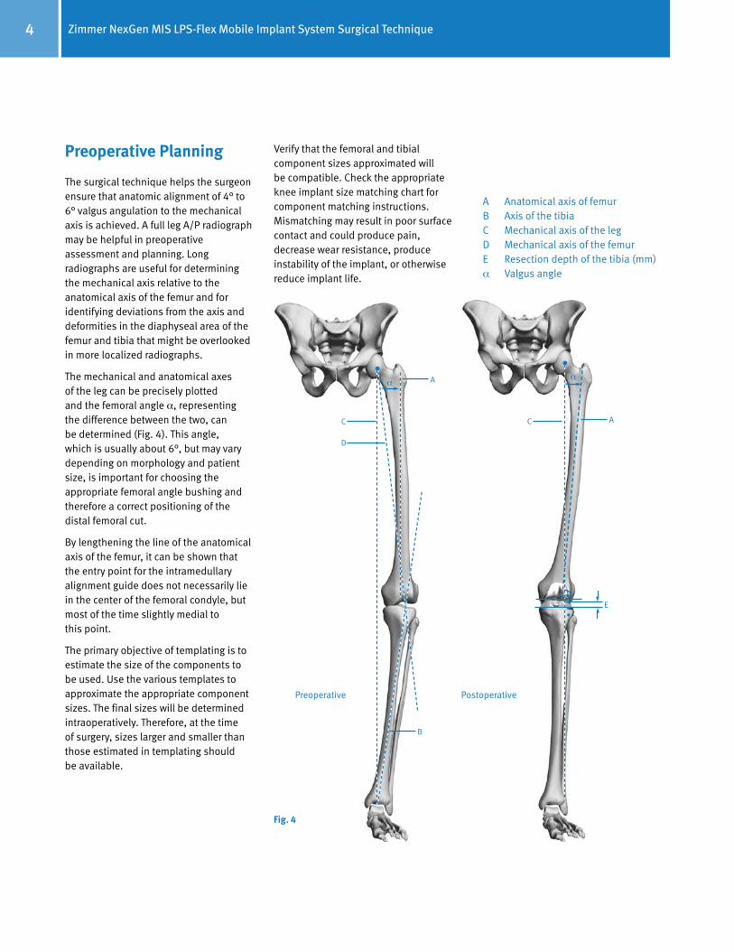
The surgical technique helps the surgeon ensure that anatomic alignment of 4° to 6° valgus angulation to the mechanical axis is achieved. A full leg A/P radiograph may be helpful in preoperative assessment and planning. Long radiographs are useful for determining the mechanical axis relative to the anatomical axis of the femur and for identifying deviations from the axis and deformities in the diaphyseal area of the femur and tibia that might be overlooked in more localized radiographs.
The mechanical and anatomical axes of the leg can be precisely plotted and the femoral angle α, representing the difference between the two, can be determined (Fig. 4). This angle, which is usually about 6°, but may vary depending on morphology and patient size, is important for choosing the appropriate femoral angle bushing and therefore a correct positioning of the distal femoral cut.
By lengthening the line of the anatomical axis of the femur, it can be shown that the entry point for the intramedullary alignment guide does not necessarily lie in the center of the femoral condyle, but most of the time slightly medial to this point.
The primary objective of templating is to estimate the size of the components to be used. Use the various templates to approximate the appropriate component sizes. The final sizes will be determined intraoperatively. Therefore, at the time of surgery, sizes larger and smaller than those estimated in templating should be available.
Verify that the femoral and tibial component sizes approximated will be compatible. Check the appropriate knee implant size matching chart for component matching instructions. Mismatching may result in poor surface contact and could produce pain, decrease wear resistance, produce instability of the implant, or otherwise reduce implant life.
Fig. 4
Preoperative Postoperative
A Anatomical axis of femurB Axis of the tibiaC Mechanical axis of the legD Mechanical axis of the femurE Resection depth of the tibia (mm)α Valgus angle

Zimmer NexGen MIS LPS-Flex Mobile Implant System Surgical Technique �
Fig. 5
Surgical Technique
Surgical technique is an important factor to consider when attempting to maximize range of motion in total knee arthroplasty. Close attention must be paid to balancing the flexion and extension gaps, clearing posterior osteophytes, releasing the posterior capsule, and reproducing the joint line.
Although the joint line may change as a result of a posterior cruciate substituting procedure, it is important that an attempt be made to maintain the joint line when high flexion is a priority. Depending on the degree, altering the joint line can cause patellofemoral issues and limit the degree of flexion. An elevated joint, for example, can cause tibiofemoral tightness in rollback and thus restrict flexion.2
When using the gap technique, it is possible that the joint line may be moved proximally, especially if there is a preoperative flexion contracture or if the selected femoral component is smaller than the A/P dimension of the femur. The alteration of the joint line can be minimized by accurately measuring for the femoral component size and performing a posterior capsulotomy to correct flexion contractures.
Patient PreparationTo prepare the limb for total knee arthroplasty, adequate muscle relaxation is required. This will facilitate the eversion of the patella, if desired, and minimize tension in the remaining quadriceps below the level of the tourniquet. It is imperative that the muscle relaxant be injected prior to inflation of the tourniquet. Alternatively, spinal or epidural anesthesia should produce adequate muscle relaxation.
If using a tourniquet, apply the proximal thigh tourniquet and inflate it with the knee in hyperflexion to maximize that portion of the quadriceps that is below the level of the tourniquet. This will help minimize restriction of the quadriceps and ease patellar eversion.
Once the patient is draped and prepped on the operating table, determine the landmarks for the surgical incision with the leg in extension.
Incision and ExposureThe skin incision can be made at the surgeon’s discretion with the leg in flexion or extension. Most surgeons find it easier to make the incision with the knee flexed. This provides skin tautness, and some retraction on the skin edges.
The initial incision is based on palpable landmarks and should initially extend approximately 1cm below the joint line and 1cm above the superior pole of the patella with the knee flexed. In a well-placed incision with supple soft tissues, this incision length can be adequate for the procedure. Larger amounts of subcutaneous fat, large amounts of fibrotic synovium, or thick inelastic quadriceps musculature may require more generous exposure and the surgeon must be cautious in retraction to avoid excessive tension on the skin.
Adjustments in incision placement may be performed by incision lengthening and repositioning as exposure proceeds. Raising full thickness flaps along the length of the incision improves mobility of the patella and facilitates partial eversion for patellar preparation while simultaneously improving mobility of the skin and reducing tension on the skin flaps during minimally invasive exposure.
The estimated size of the femoral component influences the length of the incision. Although the goal of a less invasive technique is to complete the surgery with an approximately 10cm-14cm incision, it may be necessary to extend the incision if visualization is inadequate or if there is excessive tension on the skin. If the incision needs to be extended, it is advisable to extend it gradually and only to the degree necessary. However, the advantage of this MIS technique is minimizing damage to the extensor mechanism and failure to consider excessive tension on the skin may lead to wound problems.
Make a slightly oblique parapatellar skin incision, beginning approximately 2cm proximal and medial to the superior pole of the patella, and extend it approximately 10cm to the level of the superior patellar tendon insertion at the center of the tibial tubercle (Fig. 5). Be careful to avoid disruption of the tendon insertion. This will facilitate access to the vastus medialis obliquus, and allow a minimal split of the muscle. It will also improve visualization of the lateral aspect of the joint obliquely with the patella everted.
Divide the subcutaneous tissues to the level of the retinaculum.

Zimmer NexGen MIS LPS-Flex Mobile Implant System Surgical Technique�
Fig. 6
MIS Medial Parapatellar ArthrotomyDeveloped in conjunction with Giles R. Scuderi, M.D.Minimally invasive total knee arthroplasty has become a popular procedure with surgeons using a variety of surgical exposures including the limited medial parapatellar arthrotomy; the midvastus approach; subvastus approach; and Quad Sparing™ approach. The MIS medial parapatellar arthrotomy is a versatile approach that can be easily converted to a traditional approach if necessary. Advantages of this technique include diminished post-operative morbidity, less post-operative pain, decreased blood loss, and an earlier functional recovery.3-7 However, while limiting the exposure, the integrity of the total knee arthroplasty must not be compromised. Following specific guidelines in patient selection and surgical technique, the clinical outcome can be predictable.
The MIS medial parapatellar arthrotomy is a versatile approach because it evolved from the traditional approach performed by most surgeons. The learning curve for this technique is short as surgeons gradually reduce the length of the skin incision and the arthrotomy into the quadriceps tendon in order to gain exposure of the knee joint. With lateral subluxation of the patella, instead of eversion, both the femur and tibia can be visualized without extending the arthrotomy high into the quadriceps tendon.
Begin by making a straight anterior midline incision from the superior aspect of the tibial tubercle to the superior border of the patella. The skin incision is made as small as possible in every patient, but should be extended as needed during the procedure to allow for adequate visualization and avoidance of excess skin tension. Skin under the appropriate tension should form a ‘V’ at the apices. If the skin forms a ‘U’, the incision should be lengthened.
Following subcutaneous dissection, develop full-thickness medial and lateral flaps to expose the extensor mechanism. Release of the deep fascia proximally beneath the skin and superficial to the quadriceps tendon facilitates mobilization of the skin and enhances exposure. In addition, with the knee in flexion the incision will stretch an average of 3.75cm due to the elasticity of the skin allowing broader exposure.7
The goal of minimally invasive surgery is to limit the surgical dissection without compromising the procedure. The MIS medial parapatellar arthrotomy is a shortened version of the traditional approach. Initially incise the quadriceps tendon for a length of 2-4cm above the superior pole of the patella. The arthrotomy should be of a sufficient length to sublux rather than evert the patella laterally or if the patella tendon is at risk of injury, extend the arthrotomy proximally until adequate exposure is achieved (Fig. 6).
Once the exposure is achieved, the bone preparation begins with the knee flexed at 90°, retractors are placed both medially and laterally to help aid in exposure, avoid undue skin tension, and to protect the collateral ligaments and the patella tendon. In order to aid visualization and avoid undue tension to the skin, the surgical assistants are instructed in proper placement of retractors and positioning of the knee. This will create a “mobile window” of exposure. With experience, it will become obvious that the bone preparation and resection is performed at different angles of knee flexion. In addition as the bone is resected from the proximal tibia and distal femur, there is more flexibility to the soft tissue envelope and greater exposure is achieved.

Zimmer NexGen MIS LPS-Flex Mobile Implant System Surgical Technique �
Fig. 7
MIS Midvastus ApproachDeveloped in conjunction with Aaron G. Rosenberg, M.D.The capsular incision from the superomedial corner of the patella distally to the tissue overlying the medial tibia is routine in all medial capsular approaches. Preserve approximately 1cm of peritenon and capsule medial to the patellar tendon to facilitate complete capsular closure. Split the superficial enveloping fascia of the quadriceps muscle proximally over a length of several centimeters to identify the vastus medialis obliquus (VMO) fibers inserting into the extensor mechanism. This will help mobilize the quadriceps and allow for significantly greater lateral translation of the muscle while minimizing tension on the patellar tendon insertion.
The approach becomes “midvastus” at a point proximal to the superomedial pole of the patella. Variations on the angle at which the proximal part of the capsular incision enters the muscle belly of the VMO will result in various amounts of the muscle being incised as well as variation in the amount of force required to sublux the patella laterally. Additional variables include the actual point of insertion of the VMO fibers into the patella. This insertion is variable and can take place very high (actually on the quadriceps tendon proper and not on the patellar border at all), or lower (at the midpoint of the medial patellar border), or anywhere in between. The higher the insertion of the VMO, the shorter the length of the incision into the muscle proper. The lower the insertion, the more a “low incision” into the VMO will make the exposure more like a subvastus approach and may make subluxation of the patella more difficult. It is very important to carry the capsular incision all the way to the superior border of the patella before incising the muscle belly of the VMO.
After identifying the characteristics of the VMO insertion, the vastus medialis obliquus muscle belly is split by sharp dissection approximately 1.5cm-2cm (Fig. 7). The superficial muscle has only a flimsy investing fascia and this fascia, along with the muscle belly, may be split by blunt dissection; however, the deepest layer of muscle is adherent to the more robust fascia of the VMO, which should be incised sharply.
The use of a rake to retract the capsular edges medially will reveal variable amounts of synovium. The synovium may be minimal, exuberant and inflamed, or fibrotic. Removal of excessive synovium from the medial border of the capsule at the most proximal part of the exposure distally will improve exposure and, if the synovium is fibrotic, will also reduce the tension required for exposure.
Routine medial capsular exposure proceeds by sharp dissection and removal of the anterior third of the medial meniscus, and is followed by sharp dissection of the deep medial
collateral ligament from its insertion on the proximal tibia. This occurs while the knee is flexed but may be carried out in extension at the surgeon’s discretion. This is adequate for exposure of the medial side of the knee. The experienced surgeon may want to proceed with any medial capsular releases that are predicted to be necessary to align the limb and balance the knee, or these maneuvers may be saved for later in the procedure. At this point the medial capsular retractors are removed from the wound for exposure of the lateral side.
The knee is in extension for the preliminary portion of the lateral knee exposure. First, the mobility of the patella is determined. Rakes are used to gently mobilize the patella. Mobilization may be inhibited, however, by fibrosis of the fat pad inferiorly or scarring of the suprapatellar synovium superiorly. Both conditions can be established by careful palpation and appropriate releases performed by sharp dissection. Large patellar osteophytes may be removed at this point to make patellar mobilization easier. If partial eversion—bringing the patella perpendicular to the joint (90°)—is possible, no further dissection distally in the fat pad or proximally via suprapatellar synovectomy is needed. With the patella partially everted, the bulk of the fat pad can be debrided at the surgeons discretion. The tighter the exposure, the more fat pad debridement will facilitate visualization and cutting guide placement.
The lateral joint space is then exposed by flexing the knee. It is important to avoid disrupting the extensor insertion by gently mobilizing the patella, slowly flexing the joint, and externally rotating the tibia while applying gentle pressure on the patella. An excessively thick patella may make exposure more difficult and it may help to make a standard
Zimmer NexGen MIS LPS-Flex Mobile Implant System Surgical Technique�
Fig. 8
patellar cut to decrease the thickness of the patella. If this is necessary, the patella must be protected from retraction forces with an appropriate patellar protection device.
Once the patella is subluxed, one or two standard-size Hohmann retractors placed along the lateral flare of the tibial metaphysis will maintain the eversion of the patella and the extensor mechanism. If present, the anterior cruciate ligament is released. A subperiosteal dissection along the proximal medial and lateral tibia to the level of the tibial tendon insertion can be performed as needed to mobilize the tissue envelope and to help adequately expose the bone. Release of the lateral patellofemoral ligament and/or limited release of the lateral capsule (less than 5mm) may occasionally, but rarely, be required to help minimize tension on the extensor mechanism. Pointed Hohmann and knee joint retractors may be used to mobilize the skin and arthrotomy incision to create the “mobile window” through which the remainder of the procedure is performed.
It is very important to maintain observation of the patellar tendon and the wound margins throughout the procedure to ensure that tension on these tissues are kept to an acceptable level.
MIS Subvastus ApproachDeveloped in conjunction with Russell G. Cohen, M.D.Becoming accustomed to operating through a small incision and adopting the concept of a mobile window may be facilitated by starting with a shortened medial parapatellar arthrotomy. This will help to improve visualization of the anatomy during the initial stages of becoming familiar with an MIS approach.
When comfortable with the MIS medial parapatellar approach, performing the arthrotomy through a midvastus approach will help preserve the quadriceps tendon and a portion of the medial muscular attachment. As this procedure becomes more familiar, the level of the midvastus incision should be lowered to maintain more muscle attachment.
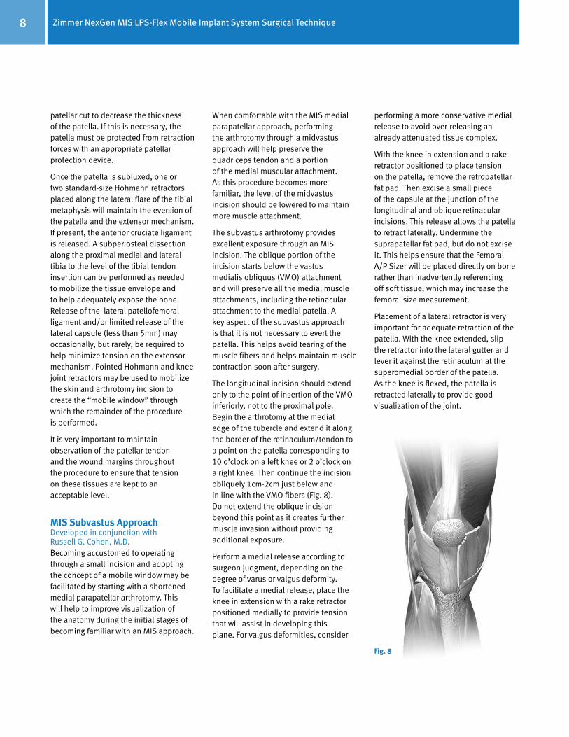
The subvastus arthrotomy provides excellent exposure through an MIS incision. The oblique portion of the incision starts below the vastus medialis obliquus (VMO) attachment and will preserve all the medial muscle attachments, including the retinacular attachment to the medial patella. A key aspect of the subvastus approach is that it is not necessary to evert the patella. This helps avoid tearing of the muscle fibers and helps maintain muscle contraction soon after surgery.
The longitudinal incision should extend only to the point of insertion of the VMO inferiorly, not to the proximal pole. Begin the arthrotomy at the medial edge of the tubercle and extend it along the border of the retinaculum/tendon to a point on the patella corresponding to 10 o’clock on a left knee or 2 o’clock on a right knee. Then continue the incision obliquely 1cm-2cm just below and in line with the VMO fibers (Fig. 8). Do not extend the oblique incision beyond this point as it creates further muscle invasion without providing additional exposure.
Perform a medial release according to surgeon judgment, depending on the degree of varus or valgus deformity. To facilitate a medial release, place the knee in extension with a rake retractor positioned medially to provide tension that will assist in developing this plane. For valgus deformities, consider
performing a more conservative medial release to avoid over-releasing an already attenuated tissue complex.
With the knee in extension and a rake retractor positioned to place tension on the patella, remove the retropatellar fat pad. Then excise a small piece of the capsule at the junction of the longitudinal and oblique retinacular incisions. This release allows the patella to retract laterally. Undermine the suprapatellar fat pad, but do not excise it. This helps ensure that the Femoral A/P Sizer will be placed directly on bone rather than inadvertently referencing off soft tissue, which may increase the femoral size measurement.
Placement of a lateral retractor is very important for adequate retraction of the patella. With the knee extended, slip the retractor into the lateral gutter and lever it against the retinaculum at the superomedial border of the patella. As the knee is flexed, the patella is retracted laterally to provide good visualization of the joint.

Zimmer NexGen MIS LPS-Flex Mobile Implant System Surgical Technique �
Lax Tensed
L M L M
Contracture
Fig. 10
Soft Tissue ReleasesTotal knee arthroplasty is a soft tissue operation as well as a bone resection operation. The objective of this procedure should be to distribute contact stresses across the artificial joint as symmetrically as possible.8
Soft tissue balancing is vital to help assure implant stability. The basic principle for ligament release entails that the tight contracted concave side is lengthened to match the convex side. The goal is to maintain a consistent and rectangular, not rhomboidal flexion and extension gap.
Zimmer MIS Quad-Sparing™ ArthrotomyTraining available at The Zimmer Institute.
Prior experience with the MIS Midvastus, Subvastus or Medial Parapatellar approach is helpful before attending the MIS Quad-Sparing Arthrotomy Course.
Fig. 9
After accessing the knee joint, balancing of the soft tissue structures and removal of osteophytes is initiated. Osteophytes may tent the medial capsule and ligamentous structures, and removal can produce a minimal correction before beginning the soft tissue release. Posteromedial osteophytes may need to be removed after the proximal tibia is resected.
When using a posterior stabilized implant, removing the posterior cruciate ligament (PCL) will make it easier to balance the collateral ligaments. It is necessary to completely resect the PCL.
Varus Release To correct most fixed varus deformities (Fig. 10), progressively release the tight medial structures until they reach the length of the lateral supporting structures. The extent of the release can be monitored by inserting laminar spreaders within the femorotibial joint and judging alignment with a plumb line. To facilitate the release, excise osteophytes from the medial femur and tibia. These osteophytes tent the medial capsule and ligamentous structures, and their removal can produce a minimal correction before beginning the soft tissue release. Posteromedial osteophytes may need to be removed after the proximal tibia is resected.
With the knee in extension, elevate a subperiosteal sleeve of soft tissue from the proximal medial tibia, including the deep medial collateral ligament, superficial medial collateral ligament, and insertion of the pes anserinus tendons. Continue the elevation with a periosteal elevator to free the posterior fibers. To improve exposure during the release, retract this subperiosteal sleeve using a Hohmann retractor.
Release the insertion of the semimembranosus muscle from the posteromedial tibia, and concurrently remove posterior osteophytes.
Continue the release distally on the anteromedial surface of the tibia for 8cm-10cm and strip the periosteum medially from the tibia. This should be sufficient for moderate deformities. For more severe deformities, continue subperiosteal stripping posteriorly and distally.
For a fixed varus deformity, the medial release includes the deep and superficial medial collateral ligament, the semitendinosus tendon and the pes anserinus tendons.
When varus malalignment is present with a flexion contracture, it may be necessary to release or transversely divide the posterior capsule.

Zimmer NexGen MIS LPS-Flex Mobile Implant System Surgical Technique�0
Lax Tensed
L M L M
Contracture
Fig. 11
Valgus Release When correcting a fixed valgus deformity, the lateral release will include the arcuate complex, iliotibial band and lateral collateral ligament. When possible the popliteus tendon is preserved to maintain flexion stability.
In contrast to that of a varus release, the principle of a valgus release is to elongate the contracted lateral structures to the length of the medial structures. Though lateral osteophytes may be present and should be removed, they do not bowstring the lateral collateral ligament in the same way as osteophytes on the medial side.
This is because the distal insertion of the lateral collateral ligament into the fibular head brings the ligament away from the tibial rim.
For a valgus release, a “piecrust” technique may be preferable. This technique allows lengthening of the lateral side while preserving a continuous soft tissue sleeve, as well as preserving the popliteus tendon, which ensures stability in flexion.
With the knee in extension and distracted with a laminar spreader, use a 15 blade to transversely cut the arcuate ligament at the joint line.
Be careful not to cut or detach the popliteus tendon. Then use the 15 blade to pierce the iliotibial band and the lateral retinaculum in a “piecrust” fashion, both proximally above the joint and distally within the joint. Following the multiple punctures, use a laminar spreader to stretch the lateral side. This should elongate the lateral side and create a rectangular extension space. Use spacer blocks to confirm ligament balance in flexion and extension
For a severe fixed valgus deformity it may be necessary to perform a complete release of the lateral supporting structures including the lateral collateral ligament, lateral capsule, arcuate complex, and popliteus tendon. This can be performed by sharply detaching the popliteus tendon, lateral collateral ligament and posterolateral capsule from the lateral femoral epicondyle. This release can then be extended around the posterolateral corner of the femur, detaching the capsular attachments. The release is extended proximally and will detach the lateral supporting structures, including the intermuscular septum to a point 7-8cm from the joint line so that the whole lateral flap is free to slide and is effectively lengthened. Another method is to osteotomize the lateral femoral epicondyle. The bone shingle created has the aforementioned soft tissue structures attached and affords the appropriate release. Occasionally, the lateral head of the gastrocnemius requires division. Rarely is division of the biceps femoris required.
Following bone resection and soft tissue release, the flexion and extension gaps are measured and should be equal and symmetrical.
Any differences must be addressed.
Zimmer NexGen MIS LPS-Flex Mobile Implant System Surgical Technique ��
Step OneResect Proximal Tibia
If preferred, the patella may be resected first. See Step 12, page 35.
Note: For EM/IM Surgical Technique, refer to NexGen Complete Knee Solution Extramedullary/Intramedullary Tibial Resector Surgical Technique (97-5997-02 Rev. 1).
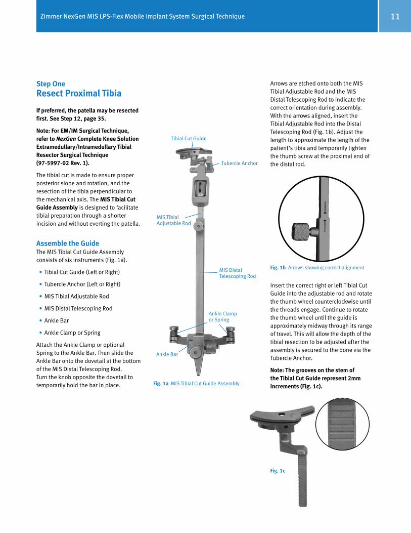
The tibial cut is made to ensure proper posterior slope and rotation, and the resection of the tibia perpendicular to the mechanical axis. The MIS Tibial Cut Guide Assembly is designed to facilitate tibial preparation through a shorter incision and without everting the patella.
Assemble the GuideThe MIS Tibial Cut Guide Assembly consists of six instruments (Fig. 1a).
• Tibial Cut Guide (Left or Right)
• Tubercle Anchor (Left or Right)
• MIS Tibial Adjustable Rod
• MIS Distal Telescoping Rod
• Ankle Bar
• Ankle Clamp or Spring
Attach the Ankle Clamp or optional Spring to the Ankle Bar. Then slide the Ankle Bar onto the dovetail at the bottom of the MIS Distal Telescoping Rod. Turn the knob opposite the dovetail to temporarily hold the bar in place.
Arrows are etched onto both the MIS Tibial Adjustable Rod and the MIS Distal Telescoping Rod to indicate the correct orientation during assembly. With the arrows aligned, insert the Tibial Adjustable Rod into the Distal Telescoping Rod (Fig. 1b). Adjust the length to approximate the length of the patient’s tibia and temporarily tighten the thumb screw at the proximal end of the distal rod.
Insert the correct right or left Tibial Cut Guide into the adjustable rod and rotate the thumb wheel counterclockwise until the threads engage. Continue to rotate the thumb wheel until the guide is approximately midway through its range of travel. This will allow the depth of the tibial resection to be adjusted after the assembly is secured to the bone via the Tubercle Anchor.
Note: The grooves on the stem of the Tibial Cut Guide represent 2mm increments (Fig. 1c).
Fig. 1b Arrows showing correct alignment
Fig. 1a MIS Tibial Cut Guide Assembly
MIS Distal Telescoping Rod
Ankle Clamp or Spring
Ankle Bar
MIS Tibial Adjustable Rod
Tibial Cut Guide
Tubercle Anchor
Fig. 1c

Zimmer NexGen MIS LPS-Flex Mobile Implant System Surgical Technique��
Attach the correct right or left Tubercle Anchor onto the corresponding side of the adjustable rod. For a left knee, the left anchor is inserted into the right hole. For a right knee, the right anchor is inserted into the left hole. Be sure that the etched line on the side of the Tubercle Anchor aligns with the corresponding etched line on the anterosuperior face of the adjustable rod (Fig. 1d).
Note: The Tibial Cut Guide and Tubercle Anchor are available in left and right configurations. If the incorrect Tubercle Anchor is used, the cut guide will not fully retract into the adjustable rod.
Position the GuidePlace the spring arms of the Ankle Clamp around the ankle proximal to the malleoli and loosen the anterior knob that provides mediolateral adjustment at the ankle. If preferred, the Spring may be used instead of the Ankle Clamp.
Loosen the knob on the proximal end of the Distal Telescoping Rod and adjust the length of the guide until the Tibial Cut Guide is positioned at the approximate depth of cut. With the Tibial Cut Guide and Tubercle Anchor contacting the bone, move the Tibial Cut Guide mediolaterally to align the rod with the medial third of the tibial tubercle (Fig. 1e). This will usually place the proximal end of the adjustable rod so it is centered below the intercondylar eminence. The Tibial Cut Guide will contact the tibia at an oblique angle and the low-profile portion of the cutting head should fit under the patellar tendon (Fig. 1f). The Tubercle Anchor is shaped to fit between the patellar tendon and the base of the cutting head.
Note: Be sure that only the low-profile portion of the cutting head extends beneath the patellar tendon.
When correctly aligned, the Distal Telescoping Rod and Tibial Adjustable Rod should be parallel to the tibia in the coronal and sagittal planes. To help avoid rotational malalignment of the rod, check its position from a direct anterior view, ie, stand at the foot of the operating table.
Insert an MIS Screw into the tibial tubercle through the hole in the Tubercle Anchor (Fig. 1g).
Fig. 1d
Fig. 1e
Fig. 1f
Tubercle Anchor
Tibial Cut Guide
Fig. 1g
Tubercle Anchor Hole

Zimmer NexGen MIS LPS-Flex Mobile Implant System Surgical Technique ��
Adjust the distal end of the MIS Distal Telescoping Rod by moving the slide at the foot of the rod medially or laterally until the guide is aligned with the mechanical axis of the tibia. The end of the MIS Distal Telescoping Rod should be positioned about 5mm-10mm medial to the midpoint between the palpable medial and lateral malleoli (Fig. 1h). When the proper M/L position is achieved, tighten the anterior knob to secure the MIS Distal Telescoping Rod to the Ankle Bar.
Loosen the knob on the side of the distal end of the MIS Distal Telescoping Rod. Then use the slide adjustment to align the rod in the sagittal plane so it is parallel to the anterior tibial shaft. This will create a 7° posterior tibial slope. If more or less slope is desired, use the slide adjustment to obtain the desired slope. Then tighten the knob. If there is a bulky bandage around the ankle, adjust the rod to accommodate the bandage. This will help ensure that the tibia will be cut with the proper slope.
Use the Hex-head Screwdriver to tighten all of the screws on the tibial assembly to maintain position.
Then use the Resection Guide through the cutting slot to assess the slope of the cut (Fig. 1i).
Set the Final Resection LevelWith the Tibial Cut Guide flush against the anteromedial edge of the tibia, insert the MIS Tibial Depth Resection Stylus into the hole on the top of the Tibial Cut Guide. For a minimal cut, swing the 2mm arm of the stylus over the defective tibial condyle. Adjust the Tibial Cut Guide up or down by rotating the thumb wheel until the tip of the 2mm stylus rests on the surface of the condyle (Fig. 1j). This will position the Tibial Cut Guide to remove 2mm of bone below the tip of the stylus.
Alternatively, swing the 10mm arm of the MIS Tibial Depth Resection Stylus over the least involved tibial condyle. Adjust the Tibial Cut Guide until the tip of the 10mm arm rests on the surface of the condyle (Fig. 1k). This will position the Tibial Cut Guide to remove 10mm of bone below the tip of the stylus.
Fig. 1h
Fig. 1j
Fig. 1k
Fig. 1i
Resection Guide
MIS Tibial Depth Resection Stylus

Zimmer NexGen MIS LPS-Flex Mobile Implant System Surgical Technique��
These two points of resection will usually not coincide. The surgeon must determine the appropriate level of resection based on patient age, bone quality, and the type of prosthetic fixation planned.
Insert an MIS Screw through the medial oblong hole on the cutting head (Fig. 1l). This hole is angled to facilitate screw insertion.
Remove the MIS Tibial Depth Resection Stylus. Place another MIS Screw through the central anterior hole on the cutting head (Fig. 1m).
Note: The MIS Depth Resection Stylus must be removed before inserting a pin or screw into the central anterior hole.
Resect the Proximal TibiaUse a 1.27mm (0.050-in) oscillating saw blade through the slot on the Tibial Cut Guide to cut the proximal surface of the tibia flat (Fig 1n). After cutting through the medial side and as far as possible into the lateral side, remove the cut guide assembly. Extend the knee and retract soft tissue on the lateral side. Then use an osteotome to complete the cut.
Note: Be careful to avoid cutting the patellar tendon when cutting the lateral side.
Use a Kocher clamp to remove the tibial bone fragment. Then trim any remaining bone spikes on the posterior and lateral aspects of the resected tibial surface.
Fig. 1l
Fig. 1m
Fig. 1n

Zimmer NexGen MIS LPS-Flex Mobile Implant System Surgical Technique ��
Step TwoEstablish Femoral Alignment
Use the 8mm IM Drill w/Step to drill a hole in the center of the patellar sulcus of the distal femur (Fig. 2a) making sure that the drill is parallel to the shaft of the femur in both the anteroposterior and lateral projections. The hole should be approximately one-half to one centimeter anterior to the origin of the posterior cruciate ligament. Medial or lateral displacement of the hole may be needed according to preoperative templating of the A/P radiograph.
The step on the drill will enlarge the entrance hole on the femur to 12mm. Suction the canal to remove medullary contents.
Fig. 2a
Fig. 2c
The Adjustable IM Alignment Guide is available with two intramedullary rod lengths. The rod on the standard instrument is 229mm (9in) long and the rod on the short instrument is 165mm (6.5in). Choose the length best suited to the length of the patient’s leg which will provide the most accurate reproduction of the anatomic axis. If the femoral anatomy has been altered, as in a femur with a long-stem hip prosthesis or with a femoral fracture malunion, use the short Adjustable IM Alignment Guide and use the extramedullary alignment technique.
Note: It is preferable to use the longest intramedullary rod to provide the most accurate replication of the anatomic axis.
Set the Adjustable IM Alignment Guide to the proper valgus angle as determined by preoperative radiographs. Check to ensure that the proper “Right” or “Left” indication (Fig. 2b) is used and engage the lock mechanism (Fig. 2c).
Fig. 2b

Zimmer NexGen MIS LPS-Flex Mobile Implant System Surgical Technique��
The Standard Cut Plate must be attached to the Adjustable IM Alignment Guide for a standard distal femoral resection (Fig. 2d).
Use a hex-head screwdriver to tighten the plate (Fig. 2e) on the guide prior to use. The screws must be loosened and the plate removed for sterilization.
If preferred, remove the Standard Cut Plate if a significant flexion contracture exists. This will allow for an additional 3mm of distal femoral bone resection (Fig. 2f).
Fig. 2d
Fig. 2e
Fig. 2f
Standard Cut Plate
Hex-head Screwdriver
Note: The optional Mini Micro Cut Plate can be used when templating has indicated that a Micro implant is likely. When the Mini Micro Cut Plate is attached to the MIS Adjustable IM Alignment Guide, one millimeter (1mm) less bone is removed. However, if a significant flexion contracture exists and no plate is attached, an additional 4mm will be removed compared to the distal femoral cut when the Mini Micro Cut Plate is attached. For less bone resection, adjustments can be made using the +2mm/-2mm holes on the Mini Distal Cut Guide.
Insert the IM guide into the hole in the distal femur. If the epicondyles are visible, the epicondylar axis may be used as a guide in setting the orientation of the Adjustable IM Alignment Guide. If desired, add the Threaded Handles to the guide and position the handles relative to the epicondyles. This does not set rotation of the femoral component, but keeps the distal cut oriented to the final component rotation.
Once the proper orientation is achieved, impact the IM guide until it seats on the most prominent condyle. After impacting, check to ensure that the valgus setting has not changed. Ensure that the guide is contacting at least one distal condyle. This will set the proper distal femoral resection.
Optional Technique: An Extramedullary Alignment Arch and Alignment Rod can be used to confirm the alignment. If this is anticipated, identify the center of the femoral head before draping. If extramedullary alignment will be the only mode of alignment, use a palpable radiopaque marker in combination with an A/P x-ray film to ensure proper location of the femoral head.

Zimmer NexGen MIS LPS-Flex Mobile Implant System Surgical Technique ��
Fig. 3a
Step ThreeCut the Distal Femur
While the Adjustable IM Alignment Guide is being inserted by the surgeon, the scrub nurse should attach the Mini Distal Femoral Cutting Guide to the 0° Distal Placement Guide (Fig. 3a). A 3° Distal Placement Guide is available which will resect the femur in 3° of flexion.
Ensure that the attachment screw is tight.
Insert the Distal Placement Guide with the cutting guide into the Adjustable IM Alignment Guide until the cutting guide rests on the anterior femoral cortex (Fig. 3b). The Mini Distal Femoral Cutting Guide is designed to help avoid soft tissue impingement.
Using the 3.2mm drill bit, drill holes through the two standard pin holes marked “0” in the anterior surface of the Mini Distal Femoral Cutting Guide, and place Headless Holding Pins through the holes (Fig. 3c).
Fig. 3b
Fig. 3d
Fig. 3c
Additional 2mm adjustments may be made by using the sets of holes marked -4, - 2, +2, and +4. The markings on the cutting guide indicate, in millimeters, the amount of bone resection each will yield relative to the standard distal resection set by the Adjustable IM Alignment Guide and Standard Cut Plate.
If more fixation is needed, use two 3.2mm Headed Screws (Fig. 3d) or predrill and insert two Hex-head Holding Pins in the small oblique holes on the Mini Distal Femoral Cutting Guide, or Silver Spring Pins may be used in the large oblique holes.
Completely loosen the attachment screw (Fig. 3e) in the Distal Placement Guide. Then use the Slaphammer Extractor to remove the IM Alignment Guide and the Distal Placement Guide.
Cut the distal femur through the cutting slot in the cutting guide using a 1.27mm (0.050-in.) oscillating saw blade (Fig. 3f). Then remove the cutting guide.
Check the flatness of the distal femoral cut with a flat surface. If necessary, modify the distal femoral surface so that it is completely flat. This is extremely important since this cut guides the placement of all subsequent guides and to help assure proper fit of the implant.
Fig. 3f
Fig. 3e

Zimmer NexGen MIS LPS-Flex Mobile Implant System Surgical Technique��
Step FourCheck Extension Gap
After the proximal tibia and distal femur have been resected, the extension gap is evaluated.
Position the knee in full extension.
Use the Spacer/Alignment Guides or MIS Spacer/Alignment Guides to check the extension gap, insert the thinnest appropriate Spacer/Alignment Guide between the resected surfaces of the femur and tibia. (Fig. 4a). If necessary insert progressively thicker Spacer/Alignment Guides until the proper soft tissue tension is obtained.
Fig. 4a
Drop the Alignment Rod with Coupler into the Spacer/Alignment Guide. Check the flatness, slope and alignment of the tibial cut.
Apply varus and valgus stress for optimal ligament balancing. Ligament releases should be performed until the extension gap is rectangular.
When the extension gap is balanced, proceed to size femur, establish external rotation and finish the femoral cuts.

Zimmer NexGen MIS LPS-Flex Mobile Implant System Surgical Technique ��
Fig. 5c
Fig. 5b
Step FiveSize Femur and Establish External Rotation
Flex the knee to 90°. Attach the MIS Threaded Handle to the medial side of the Mini A/P Sizing Guide, and place the guide flat onto the smoothly cut distal femur (Fig. 5a). Apply the guide so that the flat surface of the Mini A/P Sizing Guide is flush against the resected surface of the distal femur and the feet of the Mini A/P Sizing Guide are flush against the posterior condyles.
Slide the body of the Mini A/P Sizing Guide along the shaft to the level of the medullary canal. Position the guide mediolaterally, and check the position by looking through both windows of the guide to ensure that the medullary canal is not visible through either.
Note: Remove any osteophytes that interfere with instrument positioning.
Fig. 5a
While holding the Mini A/P Sizing Guide in place, secure the guide to the resected distal femur using a short 3.2mm (1/8-in.) Headed Screw or predrill and insert a Short-head Holding Pin into the lateral hole in the lower portion of the guide. Note: Remove the Threaded Handle before using the Screw Inserter/Extractor. Then remove the Threaded Handle and insert a 3.2mm (1/8-in.) Headed Screw or predrill and insert a Short-head Holding Pin into the medial hole in the lower portion of the guide. Do not over tighten or the anterior portion will not slide on the distal femur.
Slightly extend the knee and retract soft tissues to expose the anterior femoral cortex. Clear any soft tissue from the anterior cortex. Ensure that the leg is in less than 90° of flexion (70°-80°). This will decrease the tension of the patellar tendon to facilitate placement of the guide.
Attach the MIS Locking Boom to the Mini A/P Sizing Guide. Ensure that the skin does not put pressure on the top of the boom and potentially change its position. The position of the boom dictates the exit point of the anterior bone cut and the ultimate position of the femoral component. When the boom is appropriately positioned, lock it by turning the knurled knob (Fig. 5b).
Read the femoral size directly from the guide between the engraved lines on the sizing tower (Fig. 5c). There are eight sizes labeled “A” through “H”. With the breadth of sizes available, if the indicator is between two sizes, the size closest to the indicator is typically chosen.
If a posterior referencing technique is preferred, remove the Mini A/P Sizing Guide and go to page21, “STEP SIX Finish the Femur - Posterior Referencing”. If a blended technique is preferred, proceed to set external rotation and make final determination of posterior resection using the Posterior Referencing option.

Zimmer NexGen MIS LPS-Flex Mobile Implant System Surgical Technique�0
There are four External Rotation Plates: 0°/3° Left, 0°/3° Right, 5°/7° Left, and 5°/7° Right. Choose the External Rotation Plate that provides the desired external rotation for the appropriate knee. The 0° option can be used when positioning will be determined by the A/P axis or the epicondylar axis. Use the 3° option for varus knees. Use the 5° option for knees with a valgus deformity from 10° to 13°.
Attach the selected plate to the Mini A/P Sizing Guide (Fig. 5d).
Use a 3.2mm drill to drill through the two holes that correspond to the desired external rotation. Position two Headless Holding Pins, and impact them into the guide (Fig. 5e). Leave the head of the pin proud. If preferred, the MIS Headless Screws may be used.
Note: Do not impact the Headless Holding Pins flush with the External Rotation Plate.
Careful attention should be taken when placing the headless pins into the appropriate External Rotation Plate as these pins also set the A/P placement for the MIS Femoral Finishing Guide in the next step of the procedure. It is important to monitor the location of the anterior boom on the anterior cortex of the femur to ensure the anterior cut will not notch the femur. Positioning the anterior boom on the “high” part of the femur by lateralizing the location of the boom can often lessen the likelihood of notching the femur.
Unlock and rotate the boom of the guide medially until it clears the medial condyle. Then remove the guide, but leave the two Headless Holding Pins. These pins will establish the A/P position and rotational alignment of the Femoral Finishing Guide.
Fig. 5d
Fig. 5e

Zimmer NexGen MIS LPS-Flex Mobile Implant System Surgical Technique ��
Fig. 6b
Fig. 6c
If desired, predrill and insert two Short-head Holding Pins through the inferior holes on one or both sides of the guide.
Use the Resection Guide through the anterior cutting slot of the finishing guide, and check the medial and lateral sides to be sure the cut will not notch the anterior femoral cortex (Fig. 6d).
Alternatively, the MIS Locking Boom Attachment can be attached to the face of the femoral finishing guide. Use the MIS Locking Boom or Telescoping Locking Boom to check the location of the anterior cut and determine if notching will occur (Fig. 6e). The boom tip indicates where the anterior femoral cut will exit the bone.
Step SixFinish the Femur
Option 1 Anterior Referencing Technique
Option 2 Posterior Referencing Technique, p. 22
Option 1 Anterior Referencing Technique Select the correct size MIS Femoral Finishing Guide (silver colored) or MIS Flex Femoral Finishing Guide (gold colored) as determined by the measurement from the A/P Sizing Guide. An additional 2mm (approximately) of bone is removed from the posterior condyles when using the Flex Femoral Finishing Guide.
Place the finishing guide onto the distal femur, over the headless pins (Fig. 6a). This determines the A/P position and rotation of the guide. Remove any lateral osteophytes that may interfere with guide placement. Position the finishing guide mediolaterally by sliding it on the headless pins. The width of the MIS Femoral Finishing Guide replicates the width of the NexGen LPS/LPS-Flex femoral component. The width of the MIS Flex Femoral Finishing Guide replicates the width of the NexGen LPS-Flex femoral component. Lateralization of the femoral component is desired.
When the proper rotation and the mediolateral and anteroposterior position are achieved, secure the finishing guide to the distal femur. Use the Screw Inserter/Extractor to insert a 3.2mm Headed Screw or predrill and insert a Hex-head Holding Pin through the superior pinhole on the beveled medial side of the Femoral Finishing Guide (Fig. 6b). Then secure the lateral side in the same manner.
For additional fixation, drill the post holes using the Patellar/Femoral Drill Bit (Fig. 6c). Then insert 6.5mm x 35mm Periarticular Bone Screws through the post holes.
Fig. 6a
Fig. 6d
Fig. 6e
Zimmer NexGen MIS LPS-Flex Mobile Implant System Surgical Technique��
Fig. 6i
Fig. 6h
Fig. 6g
Fig. 6f
1
4
32
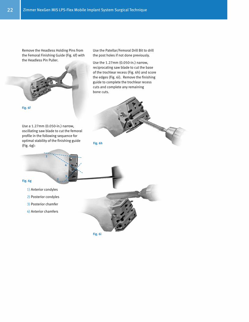
Remove the Headless Holding Pins from the Femoral Finishing Guide (Fig. 6f) with the Headless Pin Puller.
Use a 1.27mm (0.050-in.) narrow, oscillating saw blade to cut the femoral profile in the following sequence for optimal stability of the finishing guide (Fig. 6g):
1) Anterior condyles
2) Posterior condyles
3) Posterior chamfer
4) Anterior chamfers
Use the Patellar/Femoral Drill Bit to drill the post holes if not done previously.
Use the 1.27mm (0.050-in.) narrow, reciprocating saw blade to cut the base of the trochlear recess (Fig. 6h) and score the edges (Fig. 6i). Remove the finishing guide to complete the trochlear recess cuts and complete any remaining bone cuts.

Zimmer NexGen MIS LPS-Flex Mobile Implant System Surgical Technique ��
Fig. 6j
Set the rotation of the finishing guide parallel to the epicondylar axis. Check the rotation of the guide by reading the angle indicated by the Posterior Reference/Rotation Guide. The epicondylar line is rotated externally 0°-8°, (4°±4°), relative to the posterior condyles. The external rotation angle can also be set relative to the posterior condyles, lining up the degrees desired.
Remove any lateral osteophytes that may interfere with guide placement. Position the MIS Femoral Finishing Guide mediolaterally. The width of the MIS Flex Femoral Finishing Guide replicates the width of the NexGen LPS/LPS-Flex femoral component. Lateralization of the femoral component is desired.
When the proper rotation and the mediolateral and anteroposterior position are achieved, secure the finishing guide to the distal femur. Use the Screw Inserter/Extractor to insert a 3.2mm Headed Screw or predrill and insert a Hex-head Holding Pin through the superior pinhole on the beveled medial side of the Femoral Finishing Guide (Fig. 6m). Then secure the lateral side in the same manner.
Option 2 Posterior Referencing Technique Select the appropriate size MIS Femoral Finishing Guide (silver-colored) or MIS Flex Femoral Finishing Guide (gold-colored) as determined by the measurement from the A/P Sizing Guide. Additional bone is removed from the posterior condyles when using the flex finishing guide. Attach the Posterior Reference/Rotation Guide to the selected femoral finishing guide (Fig. 6j).
Fig. 6m
Fig. 6k
Fig. 6l
Lock the femoral position locator on the rotation guide to the zero position (Fig. 6k). This zero setting ensures that, when the feet are flush with the posterior condyles, the amount of posterior bone resection will average 9mm when using the standard MIS Femoral Finishing Guides, and approximately 11mm when using the MIS Flex Femoral Finishing Guides.
Technique Tip: If between sizes and you don’t want to go to larger size, you may shift the femoral cutting block 2mm anterior using the +2mm setting to reduce chance of notching the femur.
Place the finishing guide on the distal femur, bringing the feet of the rotation guide flush against the posterior condyles of the femur (Fig. 6l).

Zimmer NexGen MIS LPS-Flex Mobile Implant System Surgical Technique��
Fig. 6n
Surgeon Notes & Tips • Although a sequence of femoral
cuts has been provided, the cuts may be made in any sequence. It is recommended for the surgeon to complete the cuts in a consistent sequence to help ensure that all cuts are performed. However, the peg holes should be drilled prior to assembling the MIS Trochlear Guide.
• If the MIS Femoral Finishing Guide is used, the flexion gap should equal the extension gap.
• If the MIS Flex Femoral Finishing Guide is used, then the flexion gap will be approximately 2mm greater. For an LPS-Flex implant, use an MIS Spacer Block with the MIS LPS-Flex Spacer Block Adapter to check flexion gap.
• An oscillating saw with a narrow blade may also be used, or a reciprocating blade may be used to cut the sides and a chisel or osteotome used to cut the base of the notch.
• When establishing the mediolateral position of the femoral component, it is recommended to lateralize the component to help improve patellar tracking. Avoid positioning the component where it overhangs the bone as this may restrict flexion.
For additional fixation, drill the post holes using the Patellar/Femoral Drill Bit (Fig. 6n). Then insert 6.5mm x 35mm Periarticular Bone Screws through the post holes.
If desired, predrill and insert two Short-head Holding Pins through the inferior holes on one or both sides of the guide.
Use the Resection Guide through the anterior cutting slot of the finishing guide, and check the medial and lateral sides to be sure the cut will not notch the anterior femoral cortex (Fig. 6o).
Alternatively, the MIS Locking Boom Attachment can be attached to the face of the femoral finishing guide. Use the MIS Locking Boom or Telescoping Locking Boom to check the location of the anterior cut and determine if notching will occur (Fig. 6p). The boom tip indicates where the anterior femoral cut will exit the bone.
Fig. 6o
Fig. 6p
Use a 1.27mm (0.050-in.) narrow, oscillating saw blade to cut the femoral profile in the following sequence for optimal stability of the finishing guide (Fig. 6q):
1) Anterior condyles
2) Posterior condyles
3) Posterior chamfer
4) Anterior chamfers
Use the Patellar/Femoral Drill Bit to drill the post holes if not done previously.
Use the 1.27mm (0.050-in.) narrow, reciprocating saw blade to cut the base of the trochlear recess (Fig. 6r) and score the edges (Fig. 6s). Remove the finishing guide to complete the trochlear recess cuts and complete any remaining bone cuts.
Fig. 6q
1
4
32
Fig. 6r
Fig. 6s

Zimmer NexGen MIS LPS-Flex Mobile Implant System Surgical Technique ��
Fig. 7c Secure the MIS Notch/Chamfer Guide to the femur
Step Seven Option 1MIS Notch/Chamfer Trochlear Guide
The MIS Notch/Chamfer Trochlear Guide consists of 2 pieces for each size, the MIS Notch/Chamfer Guide and the MIS Trochlear Guide. Matching sizes must be used.
The MIS Notch/Chamfer Trochlear Guide may be used to complete the chamfer cuts, the trochlear groove, the intercondylar box and to drill the peg holes after the anterior and posterior cuts have been made with the MIS Femoral Finishing Guide.
After the anterior and posterior cuts have been made, check the flexion gap and the extension gap using the MIS Spacer Block. Make the necessary adjustments.
Knee in slight flexionPosition the appropriate size MIS Notch/Chamfer Guide onto the femur so it is flush against the resected surfaces both distally and anteriorly. Ensure that no soft tissue or osteophytes interfere with instrument positioning. Position the guide mediolaterally (Fig. 7a).
Fig. 7a Position the MIS Notch/Chamfer Guide flush against the femur
Fig. 7b Insert two short headed pins or short screws through the anterior flange
Note: The distal mediolateral profile of the MIS Notch/Chamfer Guides, anterior to the tabs, can be used to position the guide referencing the lateral condyle.
Insert two short headed pins or short screws through the anterior flange of the guide to secure the guide in position (Fig. 7b).
Knee in 90° flexionSecure the MIS Notch/Chamfer Guide to the femur distally with two Short Spring Screws or 3.2mm (1/8-in.) headed screws. Alternatively, insert two headed pins (Fig. 7c).
Fig. 7d Cut the sides and base of the intercondylar box
Fig. 7e Cut the anterior and posterior chamfers
Use a reciprocating saw to cut the sides and base of the intercondylar box (Fig. 7d). Protect the tibia with a wide osteotome.
Use the Patellar/Femoral Drill to drill the femoral post holes.
Note: Do not use the LPS-Flex Femur Peg Drill, size A, B with the MIS Notch/Chamfer Guide as there is no stop on the guide for this smaller drill. If using a micro size (A, B) LPS-Flex Femoral Component, the femoral post holes must be drilled when the anterior and posterior condyle cuts are made using the appropriate size MIS Flex Femoral Finishing Guide and the LPS-Flex Femur Peg Drill.
Then use an oscillating saw to cut the anterior chamfer and the posterior chamfer (Fig. 7e).

Zimmer NexGen MIS LPS-Flex Mobile Implant System Surgical Technique��
Remove the MIS Notch/Chamfer Guide.
Using the MIS Notch/Chamfer Guide to downsize the femurIf there is a need to downsize the femur, the MIS Notch/Chamfer and Trochlear Guide can be used for sizes C-G Standard implants and the Notch/Chamfer Guide can be used for all flex sizes.
Note: Size A, B and H MIS Trochlear Guides cannot be used for downsizing.
Select the preferred size Notch/Chamfer Guide and pin to the distal femur with two Short Spring Screws or 3.2mm (1/8-in.) headed screws (48mm length). Alternatively, insert two Hex Headed pins. Ensure that the guide is seated on the anterior and distal femur. Use a reciprocating saw to recut the sides of the intercondylar box. Use an oscillating saw to recut the anterior and posterior chamfers.
Fig. 7g MIS Trochlear Guide secured to MIS Notch/Chamfer Guide
Fig. 7h Cut the sides and base of the trochlear groove
Fig. 7f Apply the matching size MIS Trochlear Guide with the holes aligned
Apply the matching size MIS Trochlear Guide to the MIS Notch/Chamfer Guide with the holes in the Trochlear Guide aligned with the threaded holes in the Notch/Chamfer Guide (Fig. 7f). Thread the MIS Threaded Handle through one of the threaded holes to secure the Trochlear Guide to the MIS Notch/Chamfer Guide (Fig. 7g).
Protect the tibia. Use a reciprocating saw through the slots in the Trochlear Guide to cut the sides and base of the trochlear groove (Fig. 7h). Remove the Trochlear Guide, and insert an osteotome over the resected tibial surface below the trochlear groove. Then use the reciprocating saw to finish the trochlear cuts.
If downsizing for a LPS-Flex implant, use the posterior surface of the MIS Notch/Chamfer Guide for the posterior cut. If downsizing for a LPS implant, use the MIS Threaded Handle to attach the matching size MIS Trochlear Guide to the Notch/Chamfer Guide, and use the posterior surface of the MIS Trochlear Guide for the posterior cut.
Remove the MIS Trochlear and Notch/Chamfer Guides.

Zimmer NexGen MIS LPS-Flex Mobile Implant System Surgical Technique ��
Fig. 7l
Fig. 7m
With the knee in flexion, remove posterior osteophytes with a 3/4-in. curve-on-flat osteotome (Fig. 7l). Use a laminar spreader and the Posterior Femoral Retractor to improve exposure (Fig. 7m).
Step Seven Option 2MIS QS Notch Guide
Position the appropriate size MIS QS Notch Guide onto the femur so it is flush against the resected surfaces both distally and anteriorly. The MIS QS Notch Guide will not contact the anterior chamfer. Use the previously prepared trochlear recess and/or the femoral post holes to position the MIS QS Notch Guide mediolaterally.
Secure the MIS QS Notch Guide to the femur with two 3.2mm (1/8-in.) Headed Screws or predrill and insert two 3.2mm (1/8-in.) Holding Pins (Fig. 7i). Use a reciprocating saw to cut the sides and the base of the intercondylar notch (Fig. 7j). Then remove the MIS QS Notch Guide (Fig. 7k).
Fig. 7i
Fig. 7j
Fig. 7k

Zimmer NexGen MIS LPS-Flex Mobile Implant System Surgical Technique��
Step EightCheck Flexion Gap
Knee in 90° flexion
Use the Spacer/Alignment Guides or MIS Spacer/Alignment Guides to check ligament balance and joint alignment in flexion. Insert the Alignment Rod with Coupler into the guide and check the alignment of the tibial resection (Fig. 8a). Then check ligament balance. If necessary insert progressively thicker Spacer Blocks until the proper soft tissue tension is obtained. When using the MIS Flex Femoral Finishing Guide, the flexion gap will be greater than the extension gap. Position the LPS-Flex Spacer Block Adapter on top of the Spacer Block to simulate the LPS-Flex component posterior condyle dimension for sizes C-G.
Fig. 8a
Note: Do not use the CR-Flex Spacer Block Adapter since it simulates the CR-Flex component posterior condyle dimension and will result in inaccurate representation of the LPS-Flex flexion gap.
Balance Flexion/Extension GapsKnee in extension
Attach the Alignment Rod to the Alignment Rod with Coupler. Check ligament balance and limb alignment in extension.
If the tension is significantly greater in extension than in flexion, re-cut the distal femur using the appropriate instrumentation. This will enlarge the extension space.
If the tension is tighter in extension than in flexion, perform additional ligament releases.
The goal is to create a rectangular and symmetrical flexion gap between the femur and tibia.

Zimmer NexGen MIS LPS-Flex Mobile Implant System Surgical Technique ��
Fig. 9b
Fig. 9c
Fig. 9a
Attach the MIS Sizing Plate Handle to the Broach and Trialing Plate Assembly (Fig. 9e). The handle should be inserted on the medial side of the Broach Plate to provide clearance for the patella. Extend the lever on the handle and engage the tabs on the handle with the grooves on the Broach Plate by positioning the lever lateral to the dovetail, and clamp the lever to secure.
Fig. 9e
Step NinePrepare the Tibia
Note: If using the Headless Pins or Small-Head Holding Pins, predrill using the 3.2mm Bone Screw Drill.
Select the appropriate size MIS LPS-Flex Mobile Broach Plate (Fig. 9a).
Base the selection first on achieving good mediolateral coverage, and then anteroposterior coverage.
Verify that the femoral and tibial component sizes will be compatible. If there is a femoral/tibial mismatch, consider using the fixed bearing system.
Assemble the LPS-Flex Mobile Broach and Trialing Plate. Position the Trialing Plate onto the Broach Plate (Fig. 9b) so that the peg on the under side of the Trialing Plate mates with the anterior hole on the proximal surface of the Broach Plate. Align the peg and hole to prevent bending the peg. Snap the plates together tightly (Fig. 9c & 9d). Note: If the plates are not tightly snapped, it will interfere with trialing.
Fig. 9d
Ensure that the Broach and Trialing Plate Assembly is positioned as far posteriorly as possible on the lateral side without overhanging the tibia. This position may leave some bone exposed on the posteromedial tibia when the plate lines up with the posterolateral cortex.
Insert a Small Head Holding Pin into the lateral pin hole on the top face of the Broach Plate (Fig. 9f).

Zimmer NexGen MIS LPS-Flex Mobile Implant System Surgical Technique�0
Fig. 9h
Fig. 9f
Fig. 9g
When using the anterior oblique pin holes, pay special attention to the posterior aspect of the sizing plate to ensure lift-off does not occur from over tightening/seating. In extension, apply a valgus stress to view or palpate the lateral side of the tibia to check Broach Plate fit laterally.
Be sure that the component is properly positioned rotationally. Broach plate rotation and varus/valgus alignment can be checked by inserting the Alignment Rod through the hole or slot in the handle of the MIS Sizing Plate Handle (Fig. 9h). There are two options available for use of the alignment rod:
• Slot – check varus/valgus and rotational alignment
• Round hole – check slope of tibial cut
Optional Technique
Position Based on Trial Range of Motion Insert the proper size Femoral Provisional, Assembled Broach and Trialing Plates, and Articular Surface Provisional. Insert a Small-head Holding Pin through the anterior hole on the rail of the Trialing Plate. This will hold the Articular Surface Provisional in a fixed central position on the Trialing Plate.
Flex and extend the knee with the provisionals in place. With proper soft tissue balancing complete, the tibial component tends to seat itself in the position where it best articulates with the femur.
After this process has occurred, mark the position of the component with methylene blue, electrocautery, or by placing a pin or MIS Screw in the sizing plate anteriorly. Pin the broach plate in place with Small head holding pins. It is recommended to use one anterior pin hole and one hole on the opposite side of the broach plate on the plate face to assure plate stability. Ensure that the Broach Plate remains in the proper position when pinning.
Proceed to Step Eleven.
Note: Ensure that the trialing plate peg does not catch on the broach plate during removal.
Only the Small Head Holding Pins may be used through the top face of the Broach Plate. This pin will allow the Articular Surface Provisional to rotate on the assembled Broach and Trialing Plate.
It is recommended to use one hole on the top Broach Plate face and one anterior oblique hole on the opposite side if additional plate stability is needed.
A short-head pin or MIS Screw is inserted into the medial anterior oblique hole on the Broach Plate (Fig. 9g).
Note: Do not pin through the anterior oblique hole and top face hole on the same side. In this arrangement, the pins may interfere, on smaller sizes.
At this point in the procedure, perform a trial range of motion (Step Ten, Page 30) as an added check to ensure proper flexion and extension gap balancing prior to broaching the tibia.

Zimmer NexGen MIS LPS-Flex Mobile Implant System Surgical Technique ��
Step TenPerform Trial Reduction
In this step, a trial reduction is performed to check component position, patellar tracking, ROM, and joint stability.
Check the LPS/LPS-Flex Mobile Compatibility Chart for component matching instructions.
B
C
D
A
E
F
G
H
Fig. 10a
Fig. 10b
Insertion of Femoral Provisional Using Optional MIS Femoral Inserter/Extractor
A. PS or CR femoral rotation setting
B. PS or CR tension setting
C. Femoral rotation adjustment knob
D. Tension adjustment knob
E. Trigger
F. Instrument hook
G. Locking handle
H. Slaphammer slot
Determine the type of NexGen Implant or Provisional being used – in this case the Posterior Stabilized (PS). Refer to the side of the instrument, labeled PS or CR (see (A) & (B)) which corresponds with the implant or provisional type (Fig. 10a).
Initially adjust the femoral rotation setting and tension setting. For the femoral rotation setting, a good starting point is between the lines of the implant type (A). For the tension setting, start with the two lines aligned (B).
Open the locking handle (G) to attach the implant or provisional. Attach the implant or provisional by positioning the instrument hook (Fig. 10b).

Zimmer NexGen MIS LPS-Flex Mobile Implant System Surgical Technique��
If needed, turn the adjustment knob (C) to achieve the desired rotation of the femoral component (Fig. 10c).
Turn the tension adjustment knob (D) to increase (tighten) or decrease (loosen) the clamping force (Fig. 10d).
Close the locking handle to secure the instrument to the implant or provisional (Fig. 10e).
Fig. 10c
Fig. 10d
Fig. 10e
Place the Collateral Retractor laterally, an Army-Navy retractor anteriorly, and a rake retractor on the meniscal bed medially.
Align the implant or provisional onto the prepared bone, and impact the end (H).
Open the locking handle by pressing the trigger (E) to release the instrument from the implant or provisional.
If preferred, the Femoral Provisional may be positioned by hand.
Translate the Femoral Provisional laterally until the lateral peg of the provisional aligns with the drill hole in the lateral femoral condyle. Push the provisional in place beginning laterally, then medially. Be sure that soft tissue is not trapped beneath the provisional component.
Knee in extension
Check to ensure that the Femoral Provisional is flush against the resected surface on the medial condyle. Then retract the lateral side and check to make sure it is flush on the lateral side. The Femoral Provisional should be centered mediolaterally on the distal femur.
Insert the appropriate Tibial Articular Surface Provisional and perform a trial reduction. Check ligament stability in extension and in 30°, 60°, and 90° flexion. Attempt to distract the joint in flexion to ensure that it will not distract. Hyperflex the knee and check to make sure that the spine still engages the cam.
When component position, ROM, and joint stability have been confirmed, remove the Tibial Articular Surface Provisional and then the Femoral Provisional.
Fig. 10f
Removal of Femoral Provisional using Optional MIS Femoral Inserter/Extractor
Ensure that (A) and (B) are still set properly for the provisional type being used (PS).
Position the instrument hook under the provisional (F) (Fig. 10f).
Turn the tension adjustment knob (D) to tighten or loosen as needed.
Close the locking handle (G).
Attach the slaphammer (H), and extract.

Zimmer NexGen MIS LPS-Flex Mobile Implant System Surgical Technique ��
Assemble the proper size MIS Cemented Broach to the MIS Tibial Broach Impactor (Fig. 11d).
Seat the MIS Tibial Broach Impactor assembly in the corresponding Broach Plate holes (Fig. 11e).
During broaching, make sure that the broach handle remains flush against the Broach Plate and in full contact with the Broach Plate and that the broach handle does not toggle during impaction. Impact the MIS Tibial Broach Impactor assembly with care to prevent fracture of the tibia (Fig. 11f).
Fig. 11d
Step ElevenFinish the Tibia
Use the Slaphammer Extractor or small osteotome to remove the Trialing Plate, leaving the Broach Plate in place on the tibia (Fig. 11a). Avoid torquing the Trialing Plate during removal as this could damage the peg on the inferior surface (Fig. 11b).
Fig. 11a
Fig. 11c
Technique Tip – When encountering unusually hard, sclerotic bone on the proximal tibia, it is recommended to prepare the tibia prior to broaching. Attach the MIS Threaded Handle to the MIS Drill Bushing and position it on the Broach Plate (Fig. 11b). Hold the MIS Drill Bushing in place while drilling to ensure it remains in full contact with the broach plate. Using the Cemented Drill, drill half the distance to the engraved line on the Cemented Drill (Fig. 11c). This depth will prepare for the length of the keel.
Note: Make sure detents are engaged and bushing remains in full contact with the sizing plate during drilling. Fig. 11e
Fig. 11f
Fig. 11b

Zimmer NexGen MIS LPS-Flex Mobile Implant System Surgical Technique��
Remove the Tibial Broach Impactor assembly and bone plug (Fig. 11h). Gently tapping the undersurface of the impaction head can facilitate removal.
The tibial bone plug may not be fully removed by the hollow broach. A Kocher or small rongeur can be used to fully remove remaining bone (Fig. 11i).
Remove the Broach Plate.
Fig. 11i
Fig. 11g
Fig. 11h
The orientation of the broach handle is important to ensure proper and complete broaching, resulting in full seating of the tibial implant on the bone.
Caution: During impaction, take care not to move the Broach Handle anteriorly.
Broaching is complete when the Impactor Knob is fully seated against the MIS Broach Impactor Impact and the instrument bottoms out on the handle stop (Fig. 11g).
Fig. 11j

Zimmer NexGen MIS LPS-Flex Mobile Implant System Surgical Technique ��
Fig. 12d
Fig. 12a
Step TwelvePrepare the Patella
Knee flexed 90°
Turn the patella approximately 90°. To facilitate exposure, apply two towel clips to the nonarticular proximal and distal aspects of the patella, and apply gentle thumb pressure on the dorsal side of the patella.
Sharply dissect through the prepatellar bursa to expose the anterior surface of the patella. This will provide exposure for affixing the anterior surface into the Patellar Clamp.
Remove all osteophytes and synovial insertions from around the patella. Be careful not to damage tendon insertions on the bone. Use the Patellar Caliper to measure the thickness of the patella (Fig. 12a). Subtract the implant thickness from the patella thickness to determine the amount of bone that should remain after resection.
Resect the Patella
MIS Resection Guide Technique Note: The MIS Patella Resection Guide is not indicated for use with a lateral approach.
The MIS Patella Resection Guide (Fig. 12b) is positioned onto the patella without everting the patella. The Slotted Cut Guide should face the medial side. The handle will be on the lateral side.
Set the mediolateral position of the guide so that the patella ridge sits in the deepest part of the “v-shape” on the Posterior Clamp.
Use the engraved lines to visualize the position of the patella by looking through the underside of the instrument (Fig. 12c).
Fig. 12b
When orientation and position are set, clamp tightly.
Note: Take care to avoid any tilting of the patella relative to the cut slot.
Determine the pre-cut patella thicknessRead the scale on the central plunger at the base of the scale, above the “PRE CUT” arrow (Fig. 12d).
Fig. 12c

Zimmer NexGen MIS LPS-Flex Mobile Implant System Surgical Technique��
Fig. 12f
Patella Thickness – Implant Thickness = Bone Remaining
Implant Thicknesses
Note: At least 11mm of total bone will remain to allow for implant pegs if the Patellar Reamer is used.
Micro Standard
26mm 7.5mm –
29mm 7.5mm 8.0mm
32mm 8.0mm 8.5mm
35mm 8.0mm 9.0mm
38mm – 9.5mm
41mm – 10.0mm
Determine amount of bone to remain after resection.
Using the quick-release buttons on the side of the Cut Guide, slide the Cut Guide up or down until the desired amount of bone remaining is indicated on the measurement scale. Read the measurement between the engraved lines (Fig. 12e). This scale indicates the thickness of the bone that will remain after resecting the posterior patella.
Place an osteotome or retractor behind the patella to help protect the other joint surfaces and soft tissues. Then use an oscillating saw to complete the patella resection (Fig. 12g).
Release the handle and remove the instrument.
Remove the resected patella bone.
Fig. 12g
Note: When releasing the buttons at the desired resection level be sure both buttons withdraw and lock fully. If they do not engage the posts fully, the Cut Guide may become loose during cutting.
Check resection depth and orientation with the Depth Resection Guide (Fig. 12f). If the resection depth and orientation do not appear accurate, release the handle ratchet and reapply.
Fig. 12e

Zimmer NexGen MIS LPS-Flex Mobile Implant System Surgical Technique ��
Fig. 12h
Fig. 12j
Fig. 12k
Patellar Reamer Technique Total Surfacing ProcedureUse the Patellar Reamer Surfacing Guides as templates to determine the appropriate size guide and reamer. Choose the guide which fits snugly around the patella, using the smallest guide possible (Fig. 12j). If the patella is only slightly larger than the surfacing guide in the mediolateral dimension, use a rongeur to remove the medial or lateral edge until the bone fits the guide.
Insert the appropriate size Patellar Reamer Surfacing Guide into the Patellar Reamer Clamp (Fig. 12k). Turn the locking screw until tight.
Universal Saw Guide TechniqueApply the Universal Patellar Saw Guide in line with the patellar tendon. Push the patella up between the jaws of the saw guide. Level the patella within the saw guide jaws and use the thumbscrew to tighten the guide.
The amount to be resected across the top of the saw guide jaws should be approximately the same on all sides. Check to be sure that the 10mm gauge does not rotate beneath the anterior surface of the patella. If the gauge hits the anterior surface of the patella as it is rotated, this indicates that at least 10mm of bone stock will remain after the cut (Fig. 12h).
Cut the patella flat so that a smooth surface remains (Fig. 12i).
Apply the Patellar Reamer Clamp at a 90° angle to the longitudinal axis with the Patellar Reamer Surfacing Guide encompassing the articular surface of the patella. Squeeze the clamp until the anterior surface of the patella is fully seated against the fixation plate (Fig. 12l). Turn the clamp screw to hold the instrument in place. The anterior surface must fully seat upon the pins and contact the fixation plate.
Turn the depth gauge wing on the Patellar Reamer Clamp to the proper indication for the correct amount of bone that is to remain after reaming (Fig. 12m).
Fig. 12l
Fig. 12m
Fig. 12i

Zimmer NexGen MIS LPS-Flex Mobile Implant System Surgical Technique��
Fig. 12n
Attach the appropriate size Patellar Reamer Blade to the appropriate size Patellar Reamer Shaft (Fig. 12n). Use only moderate hand pressure to tighten the blade.
Do not overtighten the blade. Insert the Patellar Reamer Shaft into a drill/reamer. Insert the reamer assembly into the Patellar Reamer Surfacing Guide. Raise the reamer slightly off the bone and bring it up to full speed. Advance it slowly until the prominent high points are reamed off the bone. Continue reaming with moderate pressure until the step on the reamer shaft bottoms out on the depth gauge wing of the Patellar Reamer Clamp. Remove the reamer clamp assembly.
Proceed to “Finish the Patella” on page 39.
Insetting TechniqueUse the Patellar Reamer Insetting Guides as templates to determine the appropriate size guide and reamer. Choose the guide which will allow approximately 2mm between the superior edge of the patella and the outer diameter of the guide (Fig. 12o).
Insert the appropriate size Patellar Reamer Insetting Guide into the Patellar Reamer Clamp. Turn the locking screw until tight. Apply the Patellar Reamer Clamp at a 90° angle to the longitudinal axis with the Patellar Reamer Insetting Guide on the articular surface. Squeeze the clamp until the anterior surface of the patella is fully seated against the fixation plate. Turn the clamp screw to hold the instrument in place. The anterior surface must fully seat on the pins and contact the fixation plate.
Turn the clamp wing to the “inset” position.
2mm
Fig. 12oON OFF
Fig. 12p
Attach the appropriate size Patellar Reamer Blade to the appropriate size Patellar Reamer Shaft (Fig. 12p). Use only moderate hand pressure to tighten the blade. Do not overtighten the blade. Insert the Patellar Reamer Shaft into a drill/reamer.
Use the Patellar Reamer Depth Stops to control the amount of bone to be removed based on the thickness of the implant chosen.
Note: If using a Primary Porous Patella with Trabecular Metal TM Material, all implants are 10mm thick.
The depth gauge wing on the Patellar Reamer Clamp can be used instead of the stops to control the amount of bone remaining, rather than the amount of bone removed.
Insert the reamer assembly into the Patellar Reamer Insetting Guide. Raise the reamer slightly off the bone and bring it up to full speed. Advance it slowly until the prominent high points are reamed off the bone. Continue reaming with moderate pressure. Remove the reamer clamp assembly.

Zimmer NexGen MIS LPS-Flex Mobile Implant System Surgical Technique ��
Fig. 12s
Finish the Patella
For the NexGen Primary Porous Patella With Trabecular Metal MaterialCenter the appropriate Patellar Drill Guide over the resected patella surface with the handle on the medial side of the patella and perpendicular to the tendon. Press the drill guide firmly in place so that the teeth fully engage and the drill guide sits flat on the bone surface (Fig. 12q). Drill the peg hole making sure the drill-stop collar contacts the top of the drill guide (Fig. 12r).
Note: The Primary Porous Patellar Clamp may be used to fully seat the drill guide on hard sclerotic bone surfaces.
Fig. 12r
Fig. 12q
For the NexGen All-Polyethylene PatellaCenter the appropriate Patellar Drill Guide over the patella with the handle on the medial side of the patella and perpendicular to the tendon. Holding the drill guide firmly in place, drill the three peg holes using the Patellar/Femoral Drill Bit (Fig. 12s).

Zimmer NexGen MIS LPS-Flex Mobile Implant System Surgical Technique�0
Fig. 12tSuture Hole
Optional Patella ProtectorsThe patella may be resected before any other bone cuts. In that case, care should be taken to avoid damaging the resected surface during susequent bone cuts.
There are 3 sizes of Patella Protectors available to cover the patella while completing the remaining bone resections. Choose the size that best covers the patella – 26mm, 32mm, or 38mm. Handle with care; the spikes may be sharp.
A suture needs to be placed through the hole in the Patella Protector (Fig. 12t). Loosely tie a suture through the hole on the Patella Protector. Attach a hemostat to the end of the suture material. Leave an adequate amount of suture material to position the hemostat away from the incision.
After the initial patella cut is completed, use thumb pressure to press the Patella Protector against the bone. If the bone is particularly hard, apply the Patellar Clamp against the Patella Protector. Squeeze the clamp until the Patella Protector is fully seated against the bone.
The Patella Protector should be part of the instrument count before closing the wound. It is not intended for implantation. Completely remove the suture material at the end of the operation and before sending the instrument for cleaning.
Surgeon Notes & Tips • The suture placed through the hole in
the Patella Protector provides a tether for finding and removing the Patella Protector.
Note: The Patella Protectors are not recommended for use in an insetting technique.

Zimmer NexGen MIS LPS-Flex Mobile Implant System Surgical Technique ��
Step ThirteenPerform a Final Trial Reduction
Insert the Tibial Plate Provisional. Use the correct size MIS LPS-Mobile Tibial Plate Provisional to ensure proper fit before implanting the final components (Figs. 13a & 13b).
Fig. 13e
Fig. 13a
Place the Tibial Impactor onto the provisional and impact until completely seated (Fig. 13c).
Use the Femoral Inserter/Extractor and align the femoral provisional onto the prepared bone, and impact.
If preferred, the Femoral Provisional may be positioned by hand.
Flex and extend the knee again to ensure proper soft tissue balancing.
Insert the appropriate Tibial Articular Surface Provisional and perform a trial reduction.
Check ligament stability in extension and in 30°, 60°, and 90° flexion. Attempt to distract the joint in flexion to ensure that it will not distract. Hyperflex the knee and check to make sure that the spine still engages the cam.
Insert the Patellar Provisional onto the resected patellar surface. Perform a ROM to check patellar tracking.
Remove all provisional components.
Translate the Femoral Provisional laterally until the lateral peg of the provisional aligns with the drill hole in the lateral femoral condyle. Push the provisional in place beginning laterally, then medially. Be sure that soft tissue is not trapped beneath the provisional component.
Fig. 13b
Fig. 13c
Knee in extension
Check to ensure that the Femoral Provisional is flush against the resected surface on the medial condyle. Then retract the lateral side and check to make sure it is flush on the lateral side. The Femoral Provisional should be centered mediolaterally on the distal femur.
Attach the Articular Surface Provisional (Figs. 13d & 13e).
Fig. 13d

Zimmer NexGen MIS LPS-Flex Mobile Implant System Surgical Technique��
Step FourteenImplant Components
In this step, the final components are implanted, and the tibial articular surface is secured to the implanted tibial base plate.
After the implants have been chosen, make a final check to ensure that the femoral, tibial base plate, and tibial articular surface components match. Mix the cement. The cement should have a doughy consistency when ready for use.
Tibial Base PlatePosition the PCL Retractor posteriorly, the Collateral Soft Tissue Protector laterally, and the Collateral Retractor medially. Sublux the tibia anteriorly. Place a layer of cement on the underside of the tibial base plate and on the resected tibial surface. Position the tibial base plate onto the tibia and use the Tibial Impactor to impact it until fully seated (Fig. 14a). Thoroughly remove any excess cement in a consistent manner.
Femoral ComponentKnee in 70°-90° flexion
Place the Collateral Retractor laterally, an Army-Navy retractor anteriorly, and a rake retractor on the meniscal bed medially.
Place a layer of cement on the underside of the prosthesis and in the holes drilled in the femur.
Attach the Femoral Impactor/Extractor to the femoral component. Insert the femoral component onto the distal femur by translating the component laterally until the lateral peg aligns with the drill hole in the lateral femoral condyle. Take care to avoid scratching the implant component surfaces. Disposable, plastic Tibial Plate Protectors may be temporarily inserted onto the tibial base plate to protect the implant surfaces during insertion of the femoral component. Remove the Tibial Plate Protector after the femur is seated. Be sure that soft tissue is not trapped beneath the implant. Use a mallet to impact the component until fully seated.
Remove the Femoral Impactor/Extractor, and the retractors. Use the Femoral Impactor and Mallet to make sure the femoral component is fully impacted. Check the medial and lateral sides to make sure the femoral component is fully impacted. Remove any excess cement in a thorough and consistent manner.
Fig. 14a Use the Tibial Impactor to impact the tibial base plate.
Fig. 14b

Zimmer NexGen MIS LPS-Flex Mobile Implant System Surgical Technique ��
Tibial Articular Surface Implantation Knee in 70°-90° flexion
When the appropriately-sized tibial, femoral and patellar implant components have been implanted, allow the bone cement to cure. The articular surface provisional may be inserted to perform another trial reduction to confirm the articular surface thickness. When the desired articular surface has been determined, the articular surface implant may be inserted.
With the knee in approximately 90° of flexion, place the Articular Surface Implant against the distal portion of the femoral component with the spine of the articular surface fitting into the intercondylar notch of the femoral component. The distal condyles of the femoral component will be in contact with the articular surface (Fig. 14c).
Next, bring the tibia into extension while the articular surface is held in place against the femoral component. Axial rotation and distraction of the tibia will facilitate assembly and help prevent contact of the proximal portion of the tibial plate trunnion with the distal surface of the articular surface. As the tibia is brought into extension, the articular surface will engage the tibial plate trunnion as the knee reaches full extension (Fig. 14d).
Fig. 14d
Fig. 14c
Techniques for 17mm and 20mm Articular Surface Assembly A secondary locking screw is required for the 17mm- and 20mm-thick articular surface components.
Once the articular surface has been implanted, place the secondary locking screw (packaged with the articular surface) through the hole in the articular surface (Fig. 14e).
Fig. 14e
Attach the MIS Counter Torque Wrench to the Articulating Surface Stop on the Tibial Plate (Fig. 14f).
Tighten the MIS Counter Torque Wrench by turning the knob clockwise. Ensure that the hooks are flush with the top surface of the tibial plate. Do not over-tighten.
Alternatively, the LCCK Tibial Plate Wrench that matches the size of the implant may be used. Place the end of the wrench over the tibial base plate. Ensure that the wrench is in line with the base of the tibial base plate.
Use the LCCK Deflection Beam Torque Wrench with the 4.5mm Hex Driver Bit to torque the screw to 95 in-lbs. Do not overtorque or undertorque.
Loosen the MIS Counter Torque Wrench by turning the knob counter clockwise.
Fig. 14f

Zimmer NexGen MIS LPS-Flex Mobile Implant System Surgical Technique��
Rehabilitation Protocol
An equally important factor in gaining or maintaining high flexion after successful total knee arthroplasty is early and/or aggressive rehabilitation of the patient. Many of the standard rehabilitation protocols used in western-style hospitals today are aimed at restoring knee motion and function between 90˚ and 110˚, which is sufficient for the TKA patient to get into or out of a chair or a car. Those patients undergoing TKA who are able and willing to flex and wish to maintain preoperative flexibility may be better off with earlier and/or relatively more aggressive rehabilitation exercises.
Fig. 14i
Fig. 14h
Position the knee in flexion to continue closing the layers (Fig. 14i).
Closure
Freely irrigate the wound with the solution of choice. A drain may be placed within the capsule. Proceed with wound closure.
Please refer to package insert for complete product information, including contraindications, warnings, precautions, and adverse effects.
Close the capsule and perform a “drop and dangle” test to predict the range of motion for the patient (Fig. 14h).
NexGen All-polyethylene PatellaKnee in 70°-90° flexion
Apply cement to the anterior surface and pegs of the patellar component while in a doughy consistency. Locate the drilled peg holes and use the Patellar Clamp to insert and secure the patella in place. Fully open the jaws of the clamp and align the teeth to the anterior surface of the patella and the plastic ring to the posterior surface of the implant. Use the clamp to apply a significant amount of pressure to the implant to fully seat the implant on the patellar surface. Then remove excess cement.
Patellar Component NexGen Primary Porous Patella with Trabecular Metal MaterialKnee in 70°-90° flexion
Note: If the implant post begins to engage at an angle, the implant should be removed and repositioned perpendicular to the resected surface. Insert the patella again and reclamp, applying an even distribution of pressure on the patellar surface.
Recheck the ROM and stability of the knee.
References
1 Hvid I, Hansen SL. Trabecular bone strength patterns at the proximal tibial epiphysis. J Orthop Res. 1985;3(4):464-72.
2 Whiteside LA. Factors affecting range of motion in total knee arthroplasty. J Jpn Orthop Assoc. 1991;65:193-194.
3 Bonutti PM, Neal DJ, Kester MA: Minimal incision total knee arthroplasty using the suspended leg technique. Orthopedics 26:899-903, 2003.
4 Coon TM, Tria AJ, Lavernia C, Randall L: The economics of minimally invasive total knee surgery. Semin Arthro 16: 235-238, 2005.
5 Laskin RS: New techniques and concepts in total knee replacement. Clin Orthop 416: 151-153, 2003.
6 Scuderi GR, Tenholder M, Capeci C: Surgical approaches in mini-incision total knee arthroplasty. Clin Orthop 428: 61-67, 2004.
7 Tenholder M, Clarke HD, Scuderi GR: Minimal incision total knee arthroplasty: The early clinical experience. Clin Orthop 440: 67-76, 2005.
8 Insall JN. Surgery of the Knee. 3rd ed. New York, NY: Churchill Livingston; 2001:1553.

Zimmer NexGen MIS LPS-Flex Mobile Implant System Surgical Technique ��

Contact your Zimmer representative or visit us at www.zimmer.com
Please refer to package insert for complete product information, including contraindications, warnings, precautions, and adverse effects.
+H124975958002001/$070924I07M
97-5958-002-00 5ML Printed in USA ©2007 Zimmer, Inc.