Image Sensor Technologies for 3D Time-of-flight Range Imaging Workshops/2009 Workshop... · Range...
10
Image Sensor Technologies for 3D Time-of-flight Range Imaging Thierry Oggier Bergen, 2009 TOF Technologies Content • Overview 3D Technologies • How does a 3D TOF demodulation pixel work? • Why is a 3D TOF pixel 100 times bigger than state-of-the art CCD / CMOS pixel? • Why does a 3D TOF pixel require extremely high-speed electron transfer? • Overview of state-of-the-art 3D TOF pixel implementations • Summary / Outlook
Transcript of Image Sensor Technologies for 3D Time-of-flight Range Imaging Workshops/2009 Workshop... · Range...

Image Sensor Technologies for 3D Time-of-flight
Range Imaging
Thierry Oggier
Bergen, 2009
TOF Technologies
Content
• Overview 3D Technologies
• How does a 3D TOF demodulation pixel work?
• Why is a 3D TOF pixel 100 times bigger than state-of-the art CCD /
CMOS pixel?
• Why does a 3D TOF pixel require extremely high-speed electron
transfer?
• Overview of state-of-the-art 3D TOF pixel implementations
• Summary / Outlook
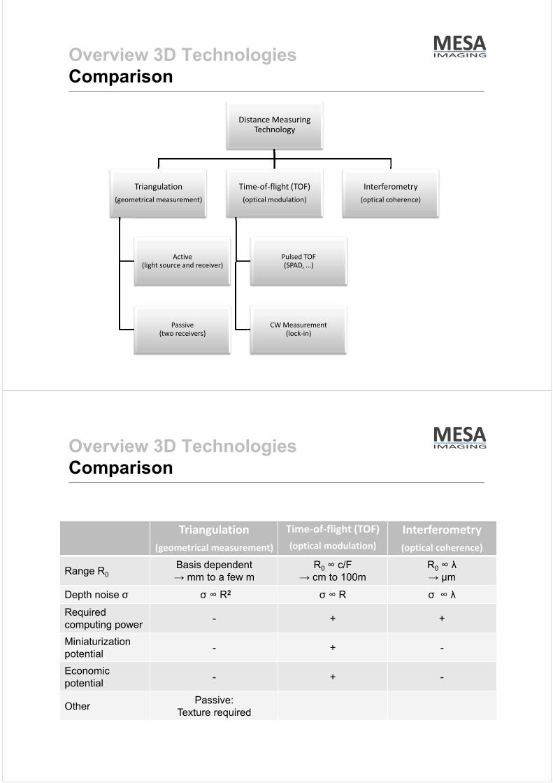
Overview 3D Technologies
Comparison
Distance Measuring
Technology
Triangulation
(geometrical measurement)
Active
(light source and receiver)
Passive
(two receivers)
Time-of-flight (TOF)
(optical modulation)
Pulsed TOF
(SPAD, …)
CW Measurement
(lock-in)
Interferometry
(optical coherence)
Overview 3D Technologies
Comparison
Triangulation
(geometrical measurement)
Time-of-flight (TOF)
(optical modulation)
Interferometry
(optical coherence)
Range R0
Basis dependent
→ mm to a few m
R0 ∞ c/F
→ cm to 100m
R0 ∞ λ
→ µm
Depth noise σ σ ∞ R2 σ ∞ R σ ∞ λ
Required
computing power- + +
Miniaturization
potential- + -
Economic
potential- + -
OtherPassive:
Texture required

Overview 3D Technologies
Comparison
Application Range [m]
Reso
lution
[m
]
10-3
100
10-6 10
3
10-9
10-6
10-3
100
3D TOF Imaging
Acquisition Samples

TOF Technologies
How does a 3D TOF pixel work?
TOF Technologies
How does a 3D TOF pixel work?
÷÷ø
öççè
æ
--
=20
13atan
AA
AAj
4
3210AAAA
B+++
=
[ ] [ ]2
2
20
2
13AAAA
A-+-
=
→ Amplitude / Quality
→ Intensity / BW
→ Phase / Distance

TOF Technologies
How does a 3D TOF pixel work?
Main
challenges for
3D TOF pixels
TOF Technologies
Why a 3D TOF pixel requires high-speed?
ndiffusion D
xt2
=D
dxdUu
x
Eu
xt
nn
drift/
22
×=
×-=D
Electron Transfer Time:
Device Simulation:
VU
mx
drift 2
7
=D
= m

TOF Technologies
Why a 3D TOF pixel requires high-speed?
System Simulation
TOF Technologies
Why are 3D TOF Pixels that big?
Note:
• Modulation at 20MHz
• Ideal imager
(perfect demodulation, no
saturation, no noise)
• No background light
• Phyiscal limitation
(photon shot noise limit)
• 10mm standard deviation
requires ~ 20ke- / sample

TOF Technologies
Why are 3D TOF Pixels that big?
Assumption:
• Camera with 1W/m2 on target
(typical for a target at 1m)
• Sun light ~50W/m2
Note:
• Modulation at 20 MHz
• Ideal imager
(perfect demodulation, no
saturation, no noise)
• Physical limitation
(photon shot noise limit)
• 10mm standard deviation
requires close to 1Me / tap
modulated and dealing with
30Me- background
TOF Technologies
Implementations (Canesta)
*Gokturk et al, “A Time-Of-Flight Depth Sensor - System Description, Issues and Solutions”, CVPR 04, Vol.3, p.35

TOF Technologies
Implementations (PMD Technology)
*Hagebeuker, „Mehrdimensionale Objekterfassung mittels PMD Sensorik“, Optik & Photonik, March 08
TOF Technologies
Implementations (University Shizuoka)
*Kawahito et al, „A CMOS time-of-flight range image sensor with gates-on-field-oxide structure“; IEEE Sensors Journal, Vol. 7, No. 12, Dec 2007

TOF Technologies
Implementations (Vrejie University Brussels)
*D. Van Nieuwenhove et al, “Novel Standard CMOS Detector using Majority Current for guiding Photo-Generated Electrons towards Detecting Junctions”,
Proceedings Symposium IEEE/LEOS Benelux Chapter, 2005, Mons
*B. Büttgen et al, “Demonstration of a Novel Drift Field Pixel Structure for the Demodulation of Modulated Light Waves with Application in Three-Dimensional
Image Capture”, SPIE Proc. Vol. 5302 (2004)
TOF Technologies
Implementations (MESA / CSEM)

TOF Technologies
Summary / Outlook
• Interferometry, triangulation and TOF technologies offer approaches
for different ranges and resolutions.
• Biggest challenges for TOF Pixel:
• the high-speed demodulation
• the required high dynamic range
• Compared to standard pixels, TOF pixel are much larger and have a
lower fill factor.
• First industrial-grade TOF camera on the market in 2009.
• High volume applications represent interesting opportunity for TOF
cameras.
Thank you for your attention!