Image Dimension Measurement System IM-6015/IM … · Image Dimension Measurement System...
24
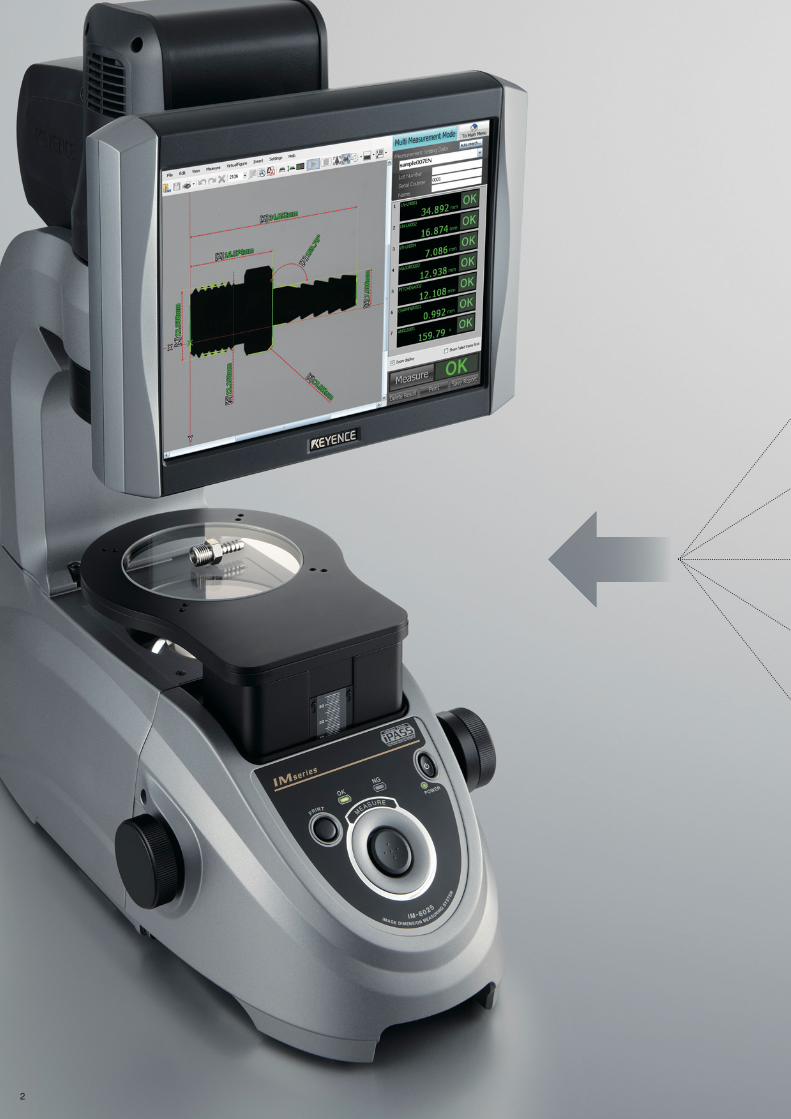
Image Dimension Measurement System IM-6015/IM-6025 Series General-purpose Model NEW General-purpose Model Instant Measurement IM Series Image Dimension Measurement System ø100 mm General-purpose Model
-
Upload
nguyentram -
Category
Documents
-
view
223 -
download
1
Transcript of Image Dimension Measurement System IM-6015/IM … · Image Dimension Measurement System...

Image Dimension Measurement System
IM-6015/IM-6025 SeriesGeneral-purpose Model
NEW
Genera
l-purp
ose M
odel
Instant MeasurementIM Series Image Dimension Measurement System
ø100 mm General-purpose Model
2

Optical comparator
Hand caliper/micrometer
Measuring microscope
Optical CMM
GD&T and Profile Measurement
System
Optical comparator × × ✓ ×
Measuring microscope × × ✓ ×
Optical CMM × ✓ × ✓
GD&T and Profile Measurement System × ✓ × ✓
Hand caliper ✓ × ✓ ×
IM Series ✓ ✓ ✓ ✓
Measurement time
Individual differences
User friendliness Data management
Comparison with various measurement systems
Faster and More PRECISEJust Place and Press
A Completely New Way of Inspecting Parts
How can functionality be improved while retaining
the advantages of conventional measurement systems?
After facing this question squarely and thoroughly,
we have reached an answer:
Combine revolutionary technology with a cutting edge
user interface.
By providing both overwhelming measurement speed
and high measurement accuracy, the IM Series
image dimension measurement system changes your
measurement operations dramatically.
Image dimension measurement system
3
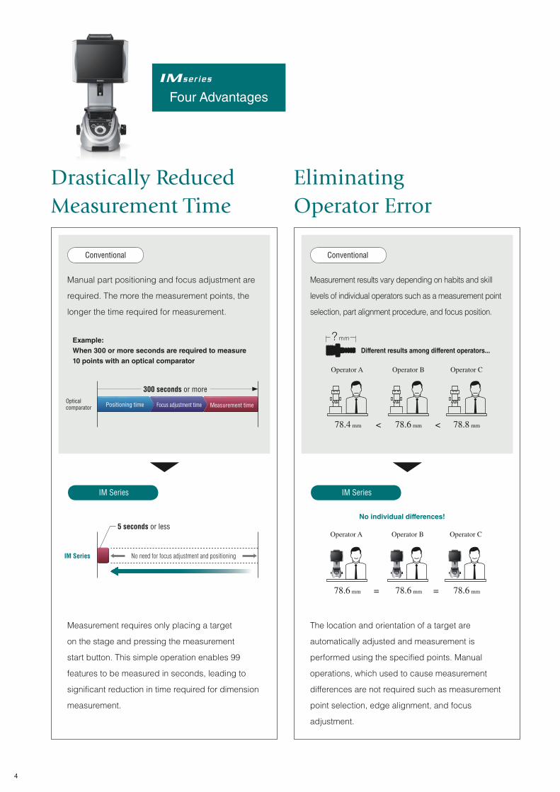
Conventional Conventional
IM Series IM Series
Manual part positioning and focus adjustment are
required. The more the measurement points, the
longer the time required for measurement.
Measurement results vary depending on habits and skill
levels of individual operators such as a measurement point
selection, part alignment procedure, and focus position.
Measurement requires only placing a target
on the stage and pressing the measurement
start button. This simple operation enables 99
features to be measured in seconds, leading to
significant reduction in time required for dimension
measurement.
The location and orientation of a target are
automatically adjusted and measurement is
performed using the specified points. Manual
operations, which used to cause measurement
differences are not required such as measurement
point selection, edge alignment, and focus
adjustment.
Different results among different operators...
No individual differences!
IM Series
Optical comparator
Example: When 300 or more seconds are required to measure 10 points with an optical comparator
300 seconds or more
Positioning time Focus adjustment time Measurement time
5 seconds or less
No need for focus adjustment and positioning
Operator A
< <
Operator B Operator C
78.4 mm 78.6 mm 78.8 mm
Four Advantages
= =
Operator A Operator B Operator C
78.6 mm 78.6 mm 78.6 mm
? mm
Drastically Reduced
Measurement Time
Eliminating
Operator Error
4

Industry first
ConventionalConventional
IM SeriesIM Series
The higher the magnification, the narrower the field
of view, which decreases operation efficiency and
user friendliness.
Data management requires time and effort such as
recording results on paper and entering data into
a PC.
The IM Series enables you to set measurement
points while checking the entire image of a target.
In addition, measurement points can be selected
simply with the mouse. This ensures simple
operation for everyone.
Measurement results are saved automatically in
the controller. Manual operations such as statistics
management of measurement results and data
transfer to a PC can also be done easily.
Partial view of a target,
requiring point-by-point
measurement
Inspection report
MEASUREMENT COMPLETE
PREPARE AN ANALYSIS/
INSPECTION REPORT
MEASUREMENT COMPLETE1
2
3
4
5
FILLOUT AN INSPECTION RECORD
INPUT DATA TO A PC
PROCESS WITH SPREADSHEET SOFTWARE
PREPARE AN ANALYSIS/INSPECTION REPORT
1
2
Easy Data
Management
Easy Operation
for Everyone
Captures the entire
image of a target and
measures
simultaneously
5

Optical Technologies for Achieving
“Place-and-Press” Measurement
6
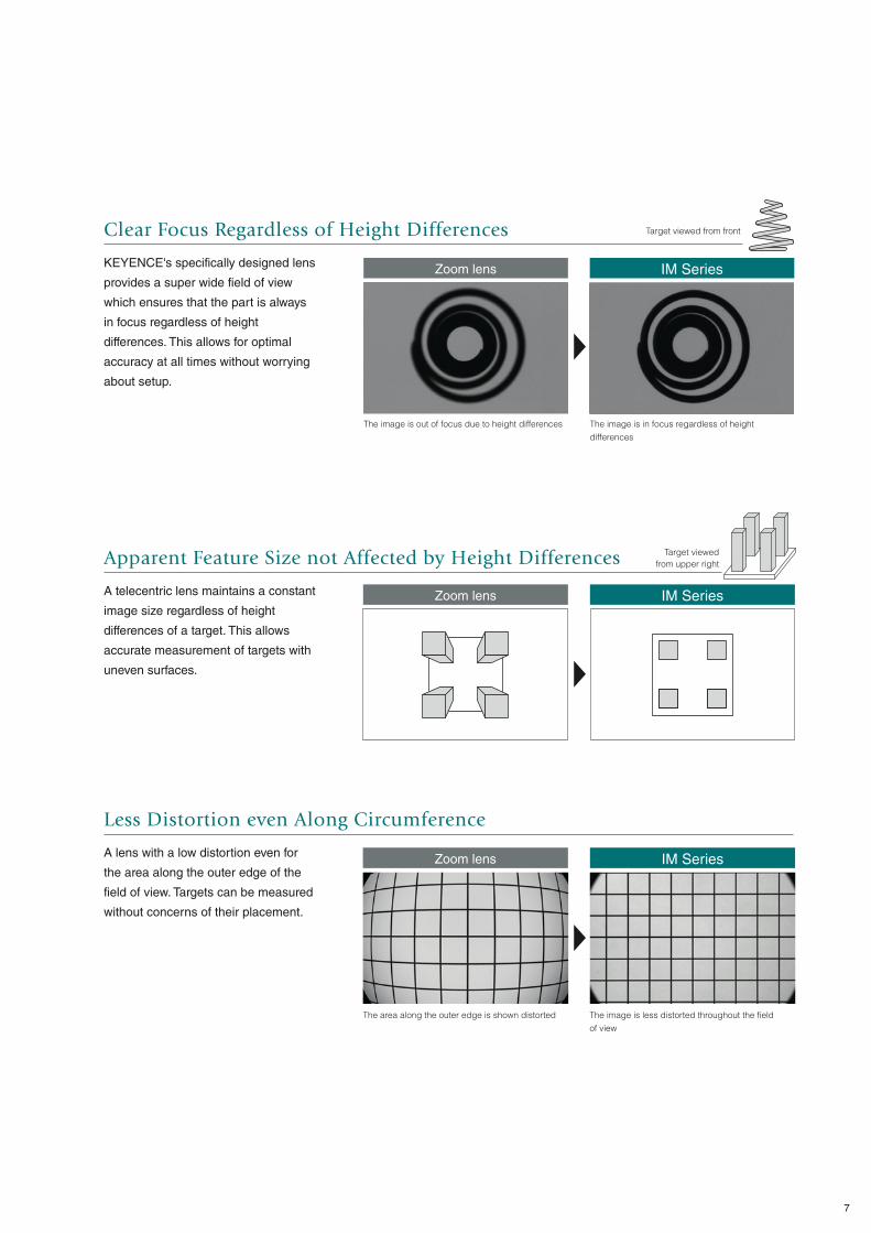
Less Distortion even Along Circumference
A lens with a low distortion even for
the area along the outer edge of the
field of view. Targets can be measured
without concerns of their placement.
Apparent Feature Size not Affected by Height Differences
A telecentric lens maintains a constant
image size regardless of height
differences of a target. This allows
accurate measurement of targets with
uneven surfaces.
Clear Focus Regardless of Height Differences
KEYENCE's specifically designed lens
provides a super wide field of view
which ensures that the part is always
in focus regardless of height
differences. This allows for optimal
accuracy at all times without worrying
about setup.
IM SeriesZoom lens
IM SeriesZoom lens
IM SeriesZoom lens
The image is out of focus due to height differences
Target viewed from front
The area along the outer edge is shown distorted
The image is in focus regardless of height
differences
The image is less distorted throughout the field
of view
Target viewed
from upper right
7
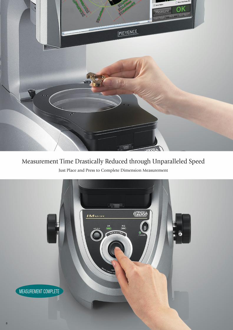
Just Place and Press to Complete Dimension Measurement
Measurement Time Drastically Reduced through Unparalleled Speed
MEASUREMENT COMPLETE
8

Industry first Pattern search for automatic location and orientation correction
The location and orientation of the
target placed on the measurement
stage are automatically detected and
measured based on the recorded
shape of the target. There is no need
for positioning of the target or
preparation of a jig at the beginning of
measurement.
Industry first Simultaneous measurement of 99 features by capturing an entire part
This is a completely new
measurement system which measures
by capturing the entire image of a
target within the field of view.
Measurement is completed in a short
time because all features are
measured after the entire image is
captured.
Industry first Batch measurement for further reduction in measurement time
The dimensions of all targets on the
stage are measured simultaneously.
Even when the targets are placed
randomly, their locations and
orientations are detected and
measured automatically.
9

Latest Image Processing Technology Eliminates Individual Differences
Same Results no Matter who Carried Out the Measurement
61.200 mm
61.200 mm
61.200 mm
61.200 mm
61.200 mm
61.200 mm
61.200 mm
61.200 mm
61.200 mm
61.200 mm
10
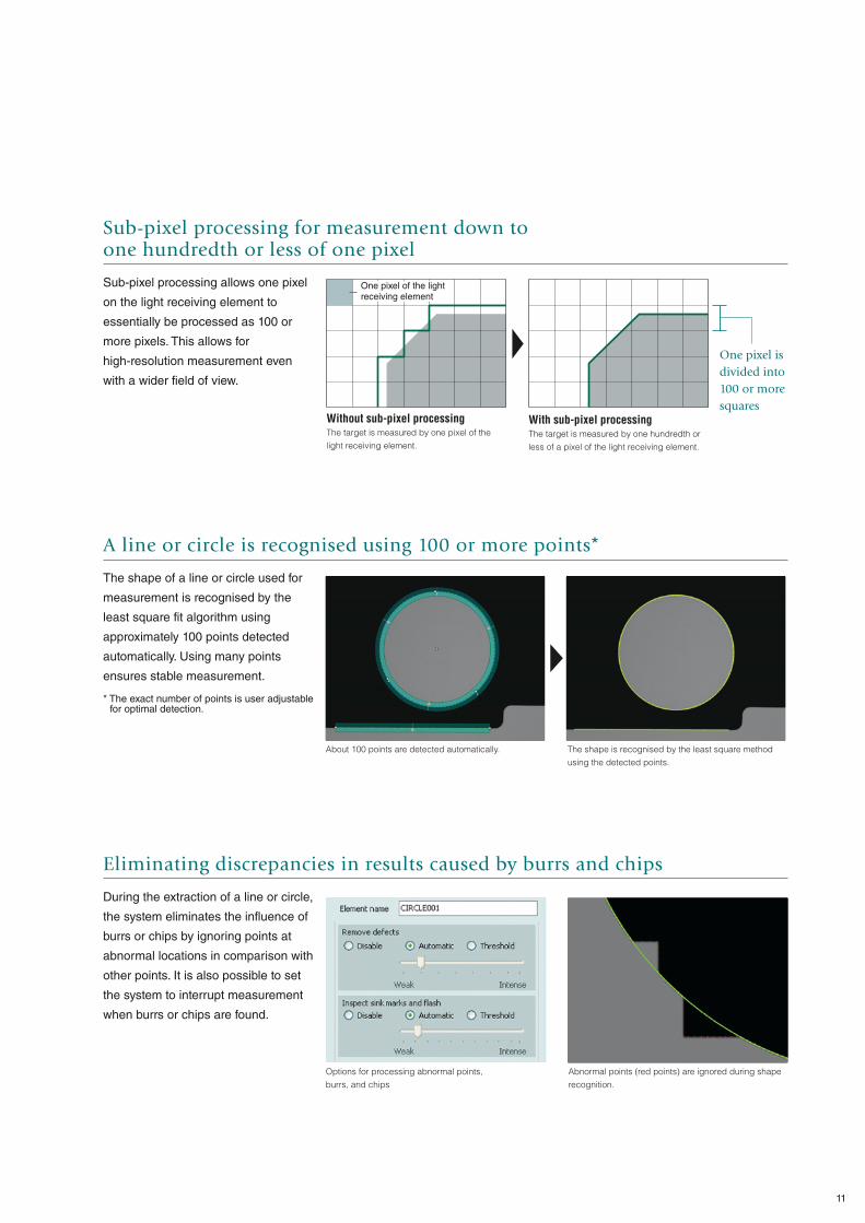
Sub-pixel processing for measurement down to one hundredth or less of one pixel
Sub-pixel processing allows one pixel
on the light receiving element to
essentially be processed as 100 or
more pixels. This allows for
high-resolution measurement even
with a wider field of view.
A line or circle is recognised using 100 or more points*
The shape of a line or circle used for
measurement is recognised by the
least square fit algorithm using
approximately 100 points detected
automatically. Using many points
ensures stable measurement.
* The exact number of points is user adjustable for optimal detection.
Eliminating discrepancies in results caused by burrs and chips
During the extraction of a line or circle,
the system eliminates the influence of
burrs or chips by ignoring points at
abnormal locations in comparison with
other points. It is also possible to set
the system to interrupt measurement
when burrs or chips are found.
One pixel is
divided into
100 or more
squaresWithout sub-pixel processingThe target is measured by one pixel of the
light receiving element.
One pixel of the light receiving element
With sub-pixel processingThe target is measured by one hundredth or
less of a pixel of the light receiving element.
About 100 points are detected automatically. The shape is recognised by the least square method
using the detected points.
Options for processing abnormal points,
burrs, and chips
Abnormal points (red points) are ignored during shape
recognition.
11
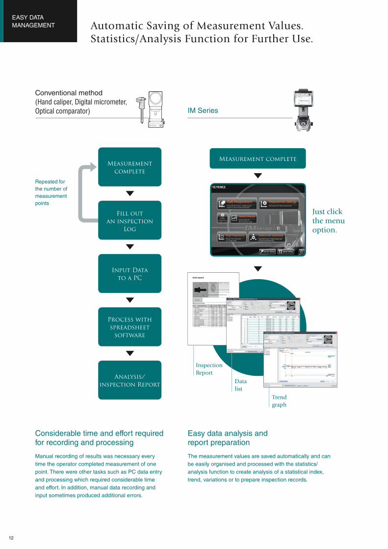
The measurement values are saved automatically and can
be easily organised and processed with the statistics/
analysis function to create analysis of a statistical index,
trend, variations or to prepare inspection records.
Trend
graph
Inspection
Report
Just clickthe menuoption.
Measurement complete
Data
list
Manual recording of results was necessary every
time the operator completed measurement of one
point. There were other tasks such as PC data entry
and processing which required considerable time
and effort. In addition, manual data recording and
input sometimes produced additional errors.
Considerable time and effort required for recording and processing
Easy data analysis and report preparation
Measurement complete
Fill out an inspection
Log
Input Datato a PC
Process withspreadsheet
software
Analysis/inspection Report
Repeated for
the number of
measurement
points
Automatic Saving of Measurement Values.Statistics/Analysis Function for Further Use.
EASY DATA
MANAGEMENT
Conventional method
(Hand caliper, Digital micrometer,
Optical comparator) IM Series
12
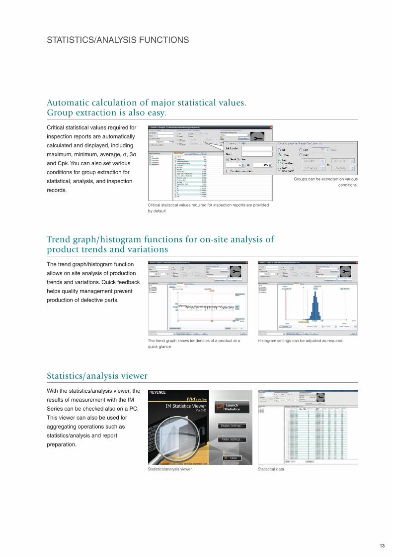
Statistics/analysis viewer Statistical data
STATISTICS/ANALYSIS FUNCTIONS
Statistics/analysis viewer
With the statistics/analysis viewer, the
results of measurement with the IM
Series can be checked also on a PC.
This viewer can also be used for
aggregating operations such as
statistics/analysis and report
preparation.
Trend graph/histogram functions for on-site analysis of product trends and variations
The trend graph/histogram function
allows on site analysis of production
trends and variations. Quick feedback
helps quality management prevent
production of defective parts.
Automatic calculation of major statistical values.Group extraction is also easy.
Critical statistical values required for
inspection reports are automatically
calculated and displayed, including
maximum, minimum, average, σ, 3σ
and Cpk. You can also set various
conditions for group extraction for
statistical, analysis, and inspection
records.
The trend graph shows tendencies of a product at a
quick glance.
Histogram settings can be adjusted as required.
Critical statistical values required for inspection reports are provided
by default.
Groups can be extracted on various
conditions.
13
Industry first Measurement Guide and animated navigation for further ease of use
Each inspection tool built into the
onboard software comes with a step
by step Measurement Guide
displayed at the upper right corner of
the screen. Clicking the Play button
starts a simple video guide which
illustrates the procedure in a few
easy steps.
The Measurement Guide displays the
next operation.
Animated navigation illustrates the procedure in a few easy to follow
steps.
Measurement
complete
Animation
replay
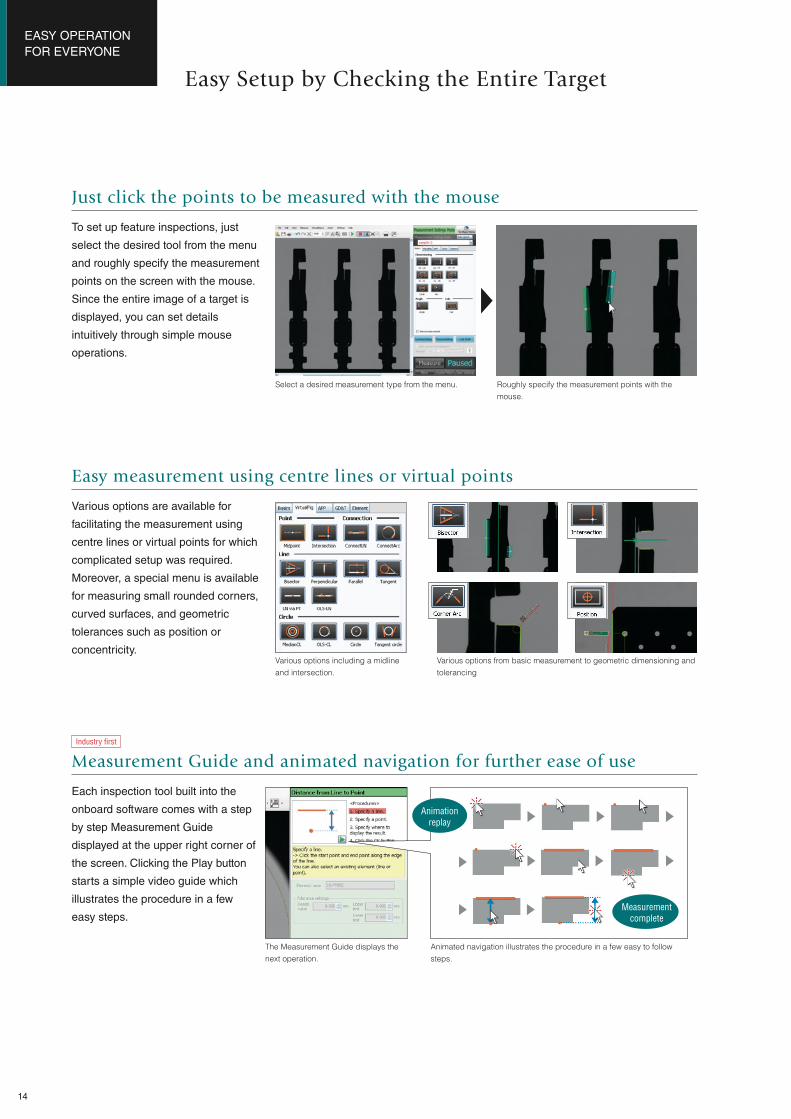
Just click the points to be measured with the mouse
To set up feature inspections, just
select the desired tool from the menu
and roughly specify the measurement
points on the screen with the mouse.
Since the entire image of a target is
displayed, you can set details
intuitively through simple mouse
operations.
Easy measurement using centre lines or virtual points
Various options are available for
facilitating the measurement using
centre lines or virtual points for which
complicated setup was required.
Moreover, a special menu is available
for measuring small rounded corners,
curved surfaces, and geometric
tolerances such as position or
concentricity.
Easy Setup by Checking the Entire Target
EASY OPERATION
FOR EVERYONE
Select a desired measurement type from the menu. Roughly specify the measurement points with the
mouse.
Various options including a midline
and intersection.
Various options from basic measurement to geometric dimensioning and
tolerancing
14

Binding multiple measurement settings Viewable as one result
SUPPORT TOOLS FOR INCREASING FUNCTIONALITY
Consolidate measurement settings
Separate measurement settings can
be bound to one data set. It is also
possible to measure multiple points
successively on one target and output
one collective result.
Industry first Automatic element extraction function
Just specify the points along the
perimeter of the target, and the
element required for measurement
such as a “line”, “circle” or “arc” is
automatically extracted. All you have to
do now is select an option for
measurement and click the extracted
element.
NEW Thread tool
A special menu is also available for
thread measurement. Dimensions
required for threading such as outer
and effective diameters can be
measured easily just by surrounding
where to measure with the mouse.
Highlight the target area. Any lines, circles, or arcs are extracted automatically.
Just surround the thread section Simple measurement also for outer, effective, and root
diameters
15

Highly rigid body and temperature sensor ensures practical installation anywhere.
The highly rigid body and built-in
temperature sensor have enabled
“installation anywhere”. Deformation is
limited as to not affect measurement
and temperature compensation
ensures accurate measurement in
the field.
Space-saving design small footprint
In addition to the compact body, the
built-in monitor saves significant space
in the installation process. It can be
installed anywhere. These important
features allow you to take your lab to
the production line for immediate part
feedback.
Traceability system diagram
The reference scales used for
manufacturing, inspection, and
calibration conform to the reference
scale of JCSS accredited calibration
laboratories to establish traceability
back to the national standard.
Performance and Reliability for Field Use
Temperature sensor ensures more stable measurement.Frame strength analysis diagram
Projector Measuring microscopeImage Measure IM Series
Small footprint
Built-in
temperature sensor
International standard
JCSS accredited calibration laboratory
Secondary standard
Common standard
Measuring instrument to be calibrated
National Metrology Institute of Japan (NMIJ) of National Institute of Advanced Industrial Science and Technology
Reference scale
Precision coordinate measuring instrument
Reference scale
IM Series image dimension measurement system
16

Supported
languages
English, German, French, Italian, Simplified Chinese, Traditional
Chinese, Thai, Korean, Japanese
Consistent support by technical sales representatives
Direct sales from manufacturer
Selection Introduction After-sales service
United States
France
Italy
Belgium
Taiwan
Japan
China
Vietnam
Thailand
Malaysia
Philippines
IndonesiaSingapore
India
Germany
United Kingdom
Mexico
Canada
Korea
Global support
We have established our original
support system to facilitate your
smooth overseas production. For
example, products are delivered from
our nearest distribution site around the
world to your overseas production site.
Without any complicated procedure,
we help you introduce our system into
your overseas production site.
Support system
Our technical sales staff respond
promptly to your requests. We offer not
only technical support but also advice
on export, import, and customs. Even
overseas, we maintain our direct sales
system from the manufacturer so that
you can receive consistent support from
selection to startup of a system.
Support in various languages
Not only operation screens on the main
unit but also other materials such as the
instruction manual are available in
various languages. After introduction
into overseas production sites, local
staff can also use this system smoothly.
Global Service Support System
17
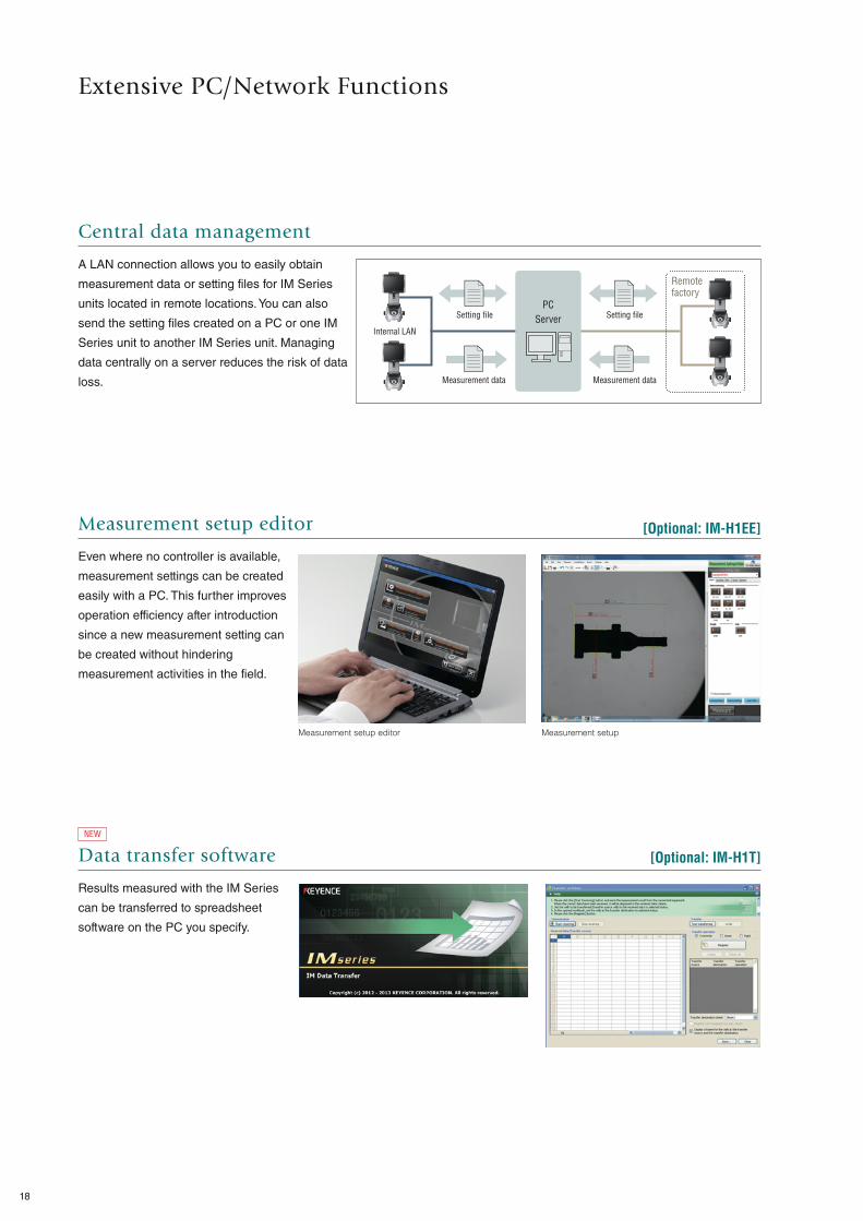
Measurement setup editor Measurement setup
[Optional: IM-H1EE]
NEW Data transfer software
Results measured with the IM Series
can be transferred to spreadsheet
software on the PC you specify.
[Optional: IM-H1T]
Central data management
A LAN connection allows you to easily obtain
measurement data or setting files for IM Series
units located in remote locations. You can also
send the setting files created on a PC or one IM
Series unit to another IM Series unit. Managing
data centrally on a server reduces the risk of data
loss.
Measurement setup editor
Even where no controller is available,
measurement settings can be created
easily with a PC. This further improves
operation efficiency after introduction
since a new measurement setting can
be created without hindering
measurement activities in the field.
Extensive PC/Network Functions
Internal LAN
Remote factory
PC
ServerSetting file Setting file
Measurement data Measurement data
18

Perimeter measurement (sealing material)
Distribution in all measurements
Profile tolerance measurement (moulding)
CAD import module Measurement setting data
Profile tolerance measurement
CAD import module
Even when a target is not at hand, an
IM setting file can be created based
on CAD diagram data.
Profile tolerance & perimeter measurement functions included
The profile tolerance (difference from
the reference dimension) or perimeter
of a target can be measured. The
reference dimension for the profile
tolerance measurement can also be
created from CAD data.
Industry first Profile statistics
Based on measurement results,
differences between design and actual
values at measurement points can be
checked visually. This function is ideal
for managing product trends.
* Distribution in all measurements/
tolerable distribution/intolerable distribution/
difference distribution/difference inclination
[Optional: IM-H1C]
CAD Data Management
19
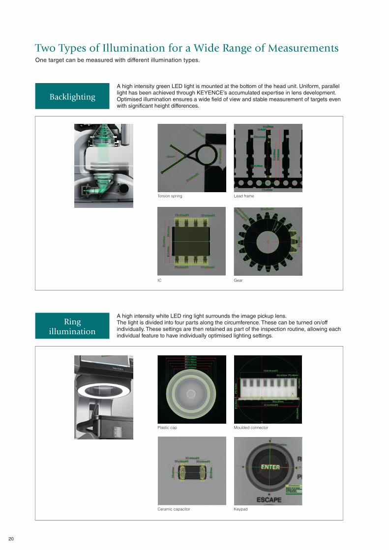
One target can be measured with different illumination types.
IC Gear
A high intensity green LED light is mounted at the bottom of the head unit. Uniform, parallel light has been achieved through KEYENCE’s accumulated expertise in lens development. Optimised illumination ensures a wide field of view and stable measurement of targets even with significant height differences.
A high intensity white LED ring light surrounds the image pickup lens. The light is divided into four parts along the circumference. These can be turned on/off individually. These settings are then retained as part of the inspection routine, allowing each individual feature to have individually optimised lighting settings.
Backlighting
Ring illumination
Plastic cap
Ceramic capacitor
Moulded connector
Keypad
Two Types of Illumination for a Wide Range of Measurements
Torsion spring Lead frame
20
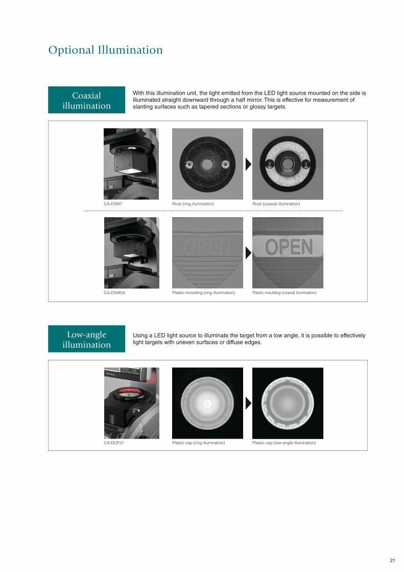
With this illumination unit, the light emitted from the LED light source mounted on the side is illuminated straight downward through a half mirror. This is effective for measurement of slanting surfaces such as tapered sections or glossy targets.
Using a LED light source to illuminate the target from a low angle, it is possible to effectively light targets with uneven surfaces or diffuse edges.
Coaxial illumination
Low-angle illumination
Rivet (ring illumination)CA-DXW7
CA-DXW5A Plastic moulding (ring illumination)
Rivet (coaxial illumination)
Plastic moulding (coaxial illumination)
CA-DLR12 Plastic cap (ring illumination) Plastic cap (low-angle illumination)
Optional Illumination
21

Low-angle illumination
CA-DLR12
Operating system environment for PC applications (statistics/analysis viewer, measurement setup editor (IM-H1EE), CAD import module (IM-H1C))
CPU Intel Core 2 Duo 1.6 GHz or higher
Memory capacity 2 GB or more
HDD free space 2 GB or more
Display colour 32 bits or more
Applicable OS
Windows XP Professional/Home Edition SP3 or later (32-bit version),
Windows Vista Ultimate/Business/Home Premium/Home Basic SP2
or later (32-bit version), Windows 7 Ultimate/Professional/Home
Premium SP1 (32/64-bit version), preinstalled version
IM standard glass
OP-86985
IM sapphire glass
OP-86986
IM illumination cable
OP-87097
IM illumination expansion base
OP-87167
IM illumination bracket (for CA-DXW7)
OP-87168
IM illumination bracket (for CA-DXW5A)
OP-87169
Precision fixturing base
OP-87501
Options
System configuration
Head
IM-6015/6025
RGB
LAN
USB
Indicator,
buzzer, etc.
Inkjet
printer
Footswitch
Controller
IM-6600E
PC
Monitor
This is a tool to fix
measurement targets.
It is useful when you measure
targets which will move on the
measurement stage.
Coaxial illumination
(50 x 50 mm)
CA-DXW7
Coaxial illumination
(35 x 35 mm)
CA-DXW5A
22

551
240
482264
ModelController IM-6600EHead IM-6015 IM-6025
Image pickup device 1" 6.6 mega pixel CMOS
Display 10.4" LCD monitor (XGA: 1024 x 768), external monitor connectable (clone output)
Light receiving lens Double telecentric lens
Field of viewWide-field measurement mode ø100 mm ø100 mm
High-precision measurement mode – ø25 mm
Minimum display unit 0.1 μm
Repetition accuracyWide-field measurement mode ±1 μm ±1 μm
High-precision measurement mode – ±0.5 μm
Measurement accuracyWide-field measurement mode ±5 μm*1 ±5 μm*1
High-precision measurement mode – ±2 μm*2
External remote input No-voltage input (with and without contact)
External output Comparator output (OK/NG/FAIL) Relay output / Rated load: 24 VDC 0.5 A /ON resistance: 50 mΩ or less
InterfaceLAN RJ-45 (10BASE-T/100BASE-TX/1000BASE-T)
USB 2.0 series A 6 ports (Front: 2, Rear: 4)
Record Hard disk drive 250 GB
Resistance to environmentOperating ambient temperature +10 to 35°C
Operating ambient humidity 20% to 80% RH (no condensation)
Illumination system
Transparent Telecentric transparent illumination (green LED)
Ring Four division (white LED)
External Externally connected illumination
Z-axis stageMoving range along Z axis 30 mm
Withstand load 3 kg
Power supplyPower supply voltage 100 to 240 VAC 50/60 Hz
Power consumption 215 VA max.
WeightController Approx. 8 kg
Head Approx. 24 kg Approx. 25 kg
*1 ±2σ in the range of ø80 mm from the centre of the stage at the operating temperature range of +23 ±1°C at the focused focal point position
*2 ±2σ in the range of ø20 mm from the centre of the stage at the operating temperature range of +23 ±1°C at the focused focal point position
173 322
343.3
Head
IM-6015/6025Controller
IM-6600E
Measurement points 99 points max. (99 x 9 points possible when the measurement setting binding function is used)
Pattern search (profile tracking function) XYθ (with 360° rotary position compensation)
Registration of measurement configuration 1000 or more*3
Measurement time 2 sec*4
Basic measurement function
Distance measurement 8 types (point-point/line-point/line-line/circle-point/circle-line/circle-circle/circle/arc)
Angle measurement Provided
Calculation Provided
Virtual line function
Point Middle point/intersection
Conjunction edge Line conjunction/circular conjunction
Line 6 types (midline/perpendicular line/parallel lines/tangent line/line passing through the point/approximate line)
Circle Middle circle/approximate circle/auxiliary circle/inscribed and circumscribed circle
Application tool
Pitch measurement Line/circumference
Pitch angle Line/circumference
Width measurement Edge width
Thickness measurement Thickness measurement/gap measurement between inner and outer diameters
Special tool Rounded corner/curved surface/oval/reticle/point position/perimeter/area/screw
GD&T
Shape tolerance Straightness/circularity/profile
Orientation tolerance Squareness/parallelism
Position tolerance Point position/concentricity
Element tool
Point Point (on a line or arc) / maximum/minimum (rectangle, circle, arc)
Line Line/centreline/peak line
Circle Circle/arc/peak circle/peak arc
Profile extraction Provided
Special tool Automatic generation/gauge line
Manual measurement Provided
Coordinate system configuration Provided
Batch configuration of tolerance Provided
Element list editing Provided
Measurement setting data binding function Provided
DXF export function Provided
*3 Depending on the measurement setting data and number of data pieces being stored *4 W/o pattern search and applied measurement
Specifications
Dimensions
Unit: mm
23
Copyright (c) 2013 KEYENCE CORPORATION. All rights reserved. IM6015-WW-C-GB 1113-2 600B64 Printed in Japan
* 6 0 0 B 6 4 *
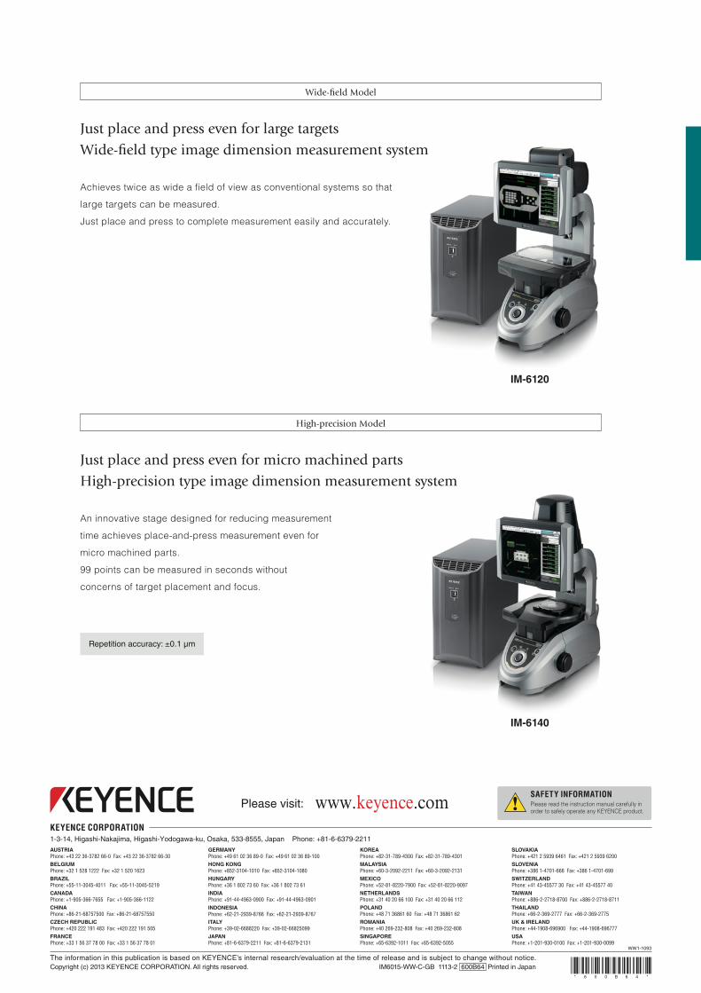
IM-6120
Achieves twice as wide a field of view as conventional systems so that
large targets can be measured.
Just place and press to complete measurement easily and accurately.
Wide-fi eld Model
Just place and press even for large targets
Wide-fi eld type image dimension measurement system
Repetition accuracy: ±0.1 μm
High-precision Model
IM-6140
An innovative stage designed for reducing measurement
time achieves place-and-press measurement even for
micro machined parts.
99 points can be measured in seconds without
concerns of target placement and focus.
Just place and press even for micro machined parts
High-precision type image dimension measurement system