Image-based Synthesis of Cao Style of Chinese Calligraphy · In Chinese calligraphy cao shu is...
10
Realistic synthesis of cao shu of Chinese calligraphy Jinhui Yu*, Qunsheng Peng State Key Lab of CAD&CG, Zhejiang University, Hangzhou 310027, P.R. China Abstract In Chinese calligraphy cao shu is regarded as a kind of free form art which differs from other styles greatly in its less constrained strokes and brush textures. In this paper we present a framework for synthesizing cao shu realistically. In our system, we adopt different brush texture patches (BTP) collected from hand-written artworks to represent the solid and hollow strokes appearing in cao shu. BTP can be extended to fit the required length by use of texture synthesis, smooth transitions between adjacent BTP over the stroke are achieved by a Markov Random Field (MRF)-based interpolation technique. With a few parameters we can reproduce typical stroke forms of cao shu, variations of brush texture, the ink amount as well as wetness of the stroke. Our model is also able to synthesize characters of cao shu with different levels of detail that are applicable to scalable font design, very high-quality publishing, computer-aided education and electronic practice of calligraphy. Keywords: Modeling, Chinese calligraphy, Line and curve generation, Desktop publishing, Fine arts. 1. Introduction Chinese calligraphy, the Chinese art of writing, has a long history in China. Through thousands years of evolution, many styles and forms have been developed and established, namely the zhuan shu (seal character), li shu (clerical script), kai shu (regular script), xing shu (semi-cursive style) and cao shu (cursive style), as shown in Fig. 1. Fig. 1. Examples of zhuan shu, li shu, kai shu, xin shu and cao shu Different styles of Chinese calligraphy express different personalities and serve for different purposes at different times. Zhuan shu and li shu are mainly for official writings and zhuan shu is the precedent of li shu. Li shu adheres to some strict prescriptions with minimal variations in the writings. Kai shu evolves from these two precedents and is the most commonly used style today due to its * Corresponding author. Tel. + 86-571-87951045; fax + 86- 571- 87951780 E-mail address: [email protected] (Jinhui Yu ) regular forms and legibility. With an injection of "motion" or flow in kai shu, the words become more fluid and indefinite. Such style is named xing shu, which is more expressive and dynamic in its forms, albeit less legible. Lastly, cao shu is one that is written with rapid strokes. Like the impressionistic paintings, cao shu tries to generate the spirit of the words while ignoring the form details. It is normally regarded as a kind of art capable of expressing thoughts and emotions. Chinese calligraphy depends heavily on its expressive brush strokes. Many brush models were proposed in the past two decades. Strassmann modeled the ink-laying process of bristle brush on paper [1]. Ink spreading effects were simulated by ink diffusion models in [2,3]. Lee proposed a model to describe the interaction between the ink and the virtual paper [4]. Creation of calligraphic artwork with a virtual brush based on classic artificial intelligence, fuzzy logic, knowledge engineering can be found in [5-7]. Way and Shih focused on Chinese landscape paintings and synthesized rock textures by drawing texture strokes on the model constructed by the user [8]. Many other papers proposed a similar brush approach to tackle the
-
Upload
truongtuong -
Category
Documents
-
view
219 -
download
5
Transcript of Image-based Synthesis of Cao Style of Chinese Calligraphy · In Chinese calligraphy cao shu is...
Realistic synthesis of cao shu of Chinese calligraphy Jinhui Yu*, Qunsheng Peng
State Key Lab of CAD&CG, Zhejiang University, Hangzhou 310027, P.R. China
Abstract
In Chinese calligraphy cao shu is regarded as a kind of free form art which differs from other styles greatly in its less constrained strokes and brush textures. In this paper we present a framework for synthesizing cao shu realistically. In our system, we adopt different brush texture patches (BTP) collected from hand-written artworks to represent the solid and hollow strokes appearing in cao shu. BTP can be extended to fit the required length by use of texture synthesis, smooth transitions between adjacent BTP over the stroke are achieved by a Markov Random Field (MRF)-based interpolation technique. With a few parameters we can reproduce typical stroke forms of cao shu, variations of brush texture, the ink amount as well as wetness of the stroke. Our model is also able to synthesize characters of cao shu with different levels of detail that are applicable to scalable font design, very high-quality publishing, computer-aided education and electronic practice of calligraphy.
Keywords: Modeling, Chinese calligraphy, Line and curve generation, Desktop publishing, Fine arts.
1. Introduction
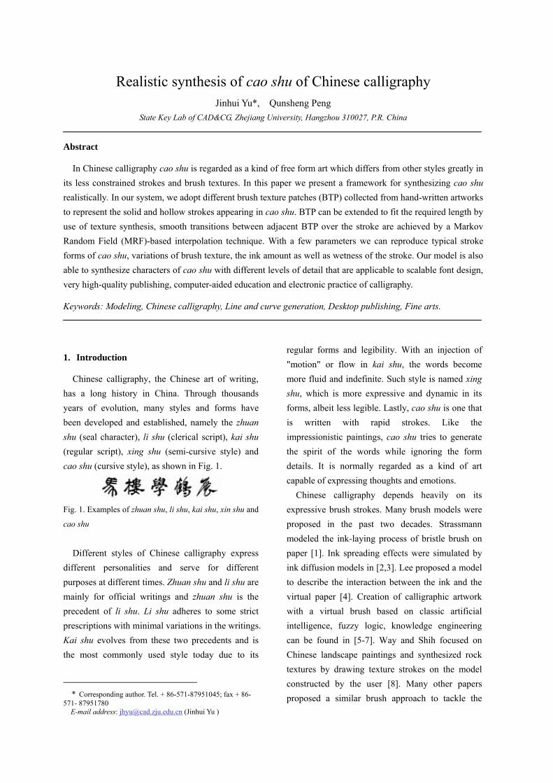
Chinese calligraphy, the Chinese art of writing, has a long history in China. Through thousands years of evolution, many styles and forms have been developed and established, namely the zhuan shu (seal character), li shu (clerical script), kai shu (regular script), xing shu (semi-cursive style) and cao shu (cursive style), as shown in Fig. 1.
Fig. 1. Examples of zhuan shu, li shu, kai shu, xin shu and
cao shu
Different styles of Chinese calligraphy express
different personalities and serve for different purposes at different times. Zhuan shu and li shu are mainly for official writings and zhuan shu is the precedent of li shu. Li shu adheres to some strict prescriptions with minimal variations in the writings. Kai shu evolves from these two precedents and is the most commonly used style today due to its
* Corresponding author. Tel. + 86-571-87951045; fax + 86-
571- 87951780 E-mail address: [email protected] (Jinhui Yu )
regular forms and legibility. With an injection of "motion" or flow in kai shu, the words become more fluid and indefinite. Such style is named xing shu, which is more expressive and dynamic in its forms, albeit less legible. Lastly, cao shu is one that is written with rapid strokes. Like the impressionistic paintings, cao shu tries to generate the spirit of the words while ignoring the form details. It is normally regarded as a kind of art capable of expressing thoughts and emotions.
Chinese calligraphy depends heavily on its expressive brush strokes. Many brush models were proposed in the past two decades. Strassmann modeled the ink-laying process of bristle brush on paper [1]. Ink spreading effects were simulated by ink diffusion models in [2,3]. Lee proposed a model to describe the interaction between the ink and the virtual paper [4]. Creation of calligraphic artwork with a virtual brush based on classic artificial intelligence, fuzzy logic, knowledge engineering can be found in [5-7]. Way and Shih focused on Chinese landscape paintings and synthesized rock textures by drawing texture strokes on the model constructed by the user [8]. Many other papers proposed a similar brush approach to tackle the

problem of painterly rendering [9-12]. Xu et al adopted a complex solid model to simulate the behavior of the brush [13]. Several image-based systems produce an image for a painterly effect by placing a jittered grid of short brush strokes over an image [14-18]. Markosian et al used the image moments of the color difference image to place rectangular brush stroke [19].
To represent the geometric shape of Chinese characters in Chinese calligraphy, several approaches have been proposed such as shape description with cubic Bezier curves and straight lines [20,21], or skeletal strokes [22]. Other methods focus on the brush stroke’s boundary [23-25] and its trajectory [26]. Shair and Rappoport introduced a parametric method to compactly represent existing outline- based oriental fonts [27]. Ip et al developed a fractal-based outline font description which is able to capture the outline characteristics of calligraphic writing [28]. Based on the shape representation of a character, the process of rasterization is applied to generate the image of the character, for the purpose such as desktop publishing [29]. Problems of generating new fonts were addressed by Coueignoux [30] and Pan et al [31]. Henmi and Yoshikawa described a virtual calligraphy system [32]. Wong and Ip used the cone and some ellipses to synthesis Chinese calligraphic writings including zhuan shu, li shu, kai shu and xing shu [33]. There are also hardware approaches to implementing brushes, such as the one by Greene [34].
Cao shu is distinctive from other styles of Chinese calligraphic writings, not only for its indefinite forms, but also for the variation of textures (hollow stroke) inside its strokes due to the speed of writing. No wonder synthesizing those characteristics of cao shu is much challenging and interesting. In this paper, we propose an image-based methodology for synthesizing cao shu of Chinese calligraphy. We target the kinds of cao shu images written by calligraphers and reproduce the visual effects we observe in those images. We started from the masterpiece by a famous Chinese
calligrapher, Mr. Zhengming Wen (1470-1559), partially because his work is difficult to model realistically using existing techniques.
We have developed a system to synthesize cao shu that mimics the styles of selected samples. At the high level, our system implements the following five steps as shown in Fig. 2.
Fig. 2. Overview of our approach
During off-line preprocessing, we collect a few typical brush texture patches (BTP) from the samples of hand written artworks to build up a brush texture library. During subsequent on-line steps, stroke skeleton or trajectory is generated by interpolating some key points specified or predefined by the user, variations of brush texture over the stroke are determined by composing different BTP along the stroke which is segmented with the threshold of curvature of the stroke skeleton. If the BTP’s length is shorter than the desired segment of the stroke skeleton, the BTP is extended to fit the required length by use of a texture synthesis technique. Smooth transitions between different BTP are achieved by a MRF-based interpolation technique. Our main contributions are the system architecture, the method of BTP blending using MRF-based interpolation and the controlling mechanism of BTP over the stroke based on the curvature value of the stroke skeleton.
The remainder of the papers is organized as follows. Section 2 describes the brush texture library. Sections 3-7 address the main issues in composition of BTP over the stroke, extension of BTP in length, blending BTP using MRF-based interpolation, stroke form, ink and wetness control. Section 8 illustrates results of synthesized characters while section 9 draws a brief conclusion.
Length
Extension
BTP
Library
Stroke
Skeleton
BTP
Blending
BTP
Composition
Synthesized
Stroke

2. Brush texture patch (BTP) library
During the writing process of cao shu, following the rapid movement of the brush, different brush textures are produced over different parts of the strokes. From the aesthetic point of view, the underlying beauty of cao shu lies in its expressive form which reveals the thoughts and feelings of the calligrapher and inspires the spontaneous response from the viewer's mind. From the physical point of view, variations in forms as well as inside textures of the strokes are caused by the decrease of ink amount due to the absorption of the paper as well as the complex movements of the brush such as moving, pressing and turning. Consequently, strokes appear wet in the first few characters and dry after them. The wet strokes usually have smooth boundary with less or no texture variations, while dry strokes have rough boundary with more texture variations, as illustrated by Mr. Wen’s calligraphic work in Fig. 3.
Fig. 3. Characters digitized from Mr. Zhengming Wen’s
calligraphic work
The first step of our approach is to collect suitable BTPs from hand written samples to build up the brush texture library. After careful study of Mr. Wen’s artwork with 180 characters, we copy manually some typical BTPs with different amount of ink and wetness, namely BTPm (m=1,…NBTP, where NBTP is the number of the texture patches collected and in our implementation NBTP is set to 9), those BTPs are of the same size LBTP × WBTP where LBTP and WBTP are the length and width of the
BTP respectively, and WBTP corresponds to the normal width of strokes in hand written samples. All BTPs are placed in the decreasing order of ink amount in the brush texture, as shown in the left column in Fig. 4.
Fig. 4. BTPs collected from samples (left column) and
BTPs extended in length (right column)
3. BTP composition
From Fig. 3 we can see that hollow strokes appear most likely in the segments between stroke turning points at which the stroke changes its curvature. Hollow strokes are connected with solid strokes or other hollow strokes with different textures at turning points of the stroke. In this section we describe how to detect turning points along the stroke in our model.
Fig.5. Stroke skeleton with turning points detected using
δc= 0.001 (left) andδc=0.02 (right).
We generate the skeleton of a stroke by
interpolating a set of key points (bigger dots in Fig. 5) specified or predefined by the user. Suppose the skeleton of stroke Pi has N points (i=1,..N), among them there are M turning points TurnPj (j=1,...M and M<N). We determine these turning points by calculating the curvature of the curve at each sample point and comparing it with a prescribed thresholdδc, if the curvature value is greater thanδ
c, the current sample point is regarded as a turning point, otherwise not. Obviously, smallδ c would
result more turning points detected, as shown by lines across the stroke in Fig. 5. Our interface displays positions of the turning points over the stroke, the user can varyδc to get the result desired. With turning points detected the stroke is divided into M-1 segments, each segment is associated with an appropriate BTP according to some aesthetic rules as well as the physical movement and state of the brush at the time. Detailed mechanism to select BTP for each segment is described in section 7.
Since a stroke may be composed of segment with different BTPs, the visual continuity between these BTPs must be guaranteed. To this end, we lay the solid stroke or strokes with heavy ink across turning points, transitions between those strokes and other hollow strokes actually take place near the turning points in each segment. Let TranP1 and TranP2 denote points at which transitions take place in the segment and TurnPj and TurnPj+1 be the end points of the segment, the position of TranP1 and TranP2
can be determined with a local coordinate l∈[0,1] (where l=0 corresponds to TurnPj and l=1 corresponds to TurnPj+1 ). To avoid stiff appearance of the resultant stroke, we let parameters l1 and l2
vary randomly in the range [0.1,0.35] and [0.65,0.9], respectively to pick up the transition points. With TranP1 and TranP2, the segment defined by TurnPj and TurnPj+1 can be divided further into three parts, the appearance of the segment is then determined by inserting the appropriate BTPs in the middle part and other strokes in the two ending parts, as detailed in section 5.
4. BTP extension in length
Although strokes in cao shu may vary in both width and length, variations in length are usually more dynamic. Thus, the BTP collected may not be long enough to fit the length of the synthesized stroke, it is therefore necessary to extend the BTP to fit the required length.
Problem of extending BTP to the required length actually falls in the area of texture synthesis, we adopt the idea proposed in [35] to synthesize the brush texture in real-time with a simplified Markov
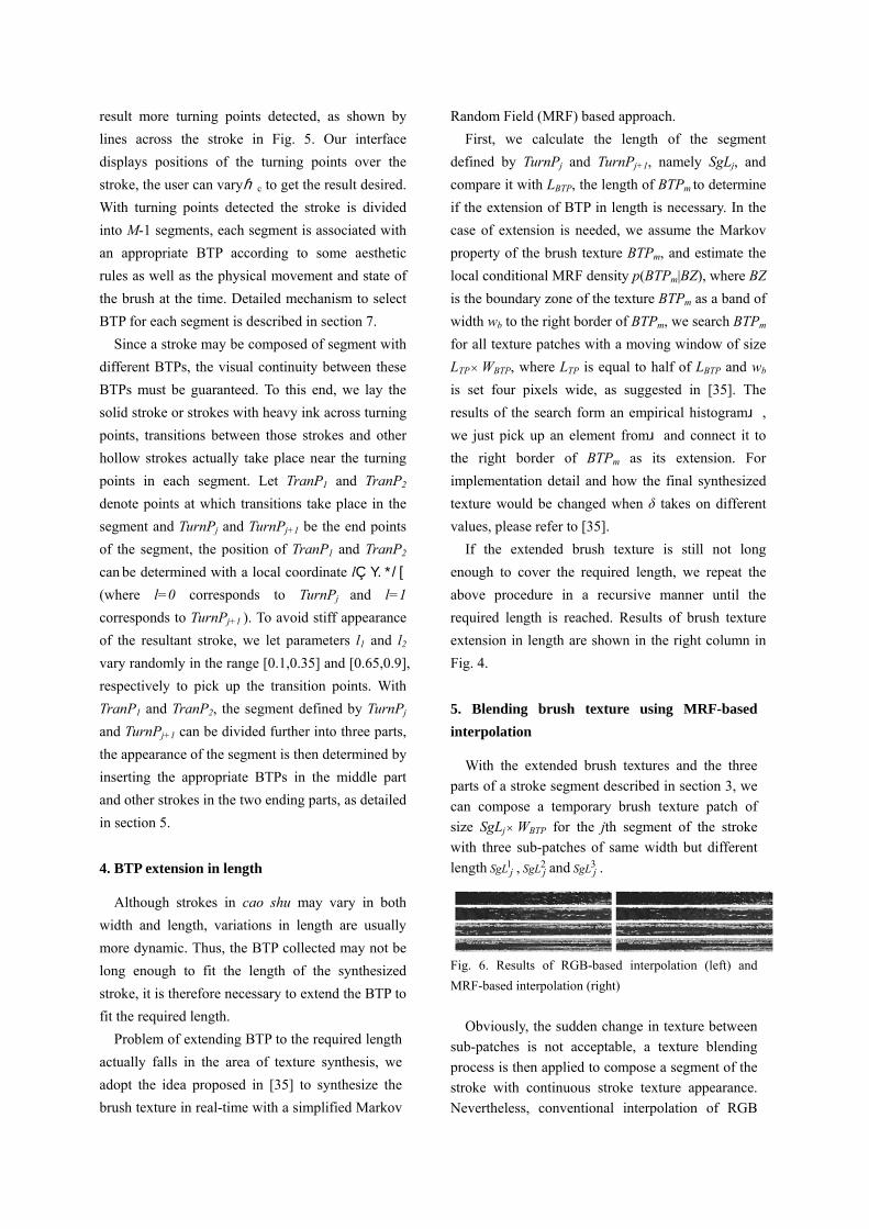
Random Field (MRF) based approach. First, we calculate the length of the segment
defined by TurnPj and TurnPj+1, namely SgLj, and compare it with LBTP, the length of BTPm to determine if the extension of BTP in length is necessary. In the case of extension is needed, we assume the Markov property of the brush texture BTPm, and estimate the local conditional MRF density p(BTPm|BZ), where BZ is the boundary zone of the texture BTPm as a band of width wb to the right border of BTPm, we search BTPm for all texture patches with a moving window of size LTP × WBTP, where LTP is equal to half of LBTP and wb is set four pixels wide, as suggested in [35]. The results of the search form an empirical histogramψ, we just pick up an element fromψand connect it to the right border of BTPm as its extension. For implementation detail and how the final synthesized texture would be changed when δ takes on different values, please refer to [35]. If the extended brush texture is still not long enough to cover the required length, we repeat the above procedure in a recursive manner until the required length is reached. Results of brush texture extension in length are shown in the right column in Fig. 4. 5. Blending brush texture using MRF-based interpolation
With the extended brush textures and the three parts of a stroke segment described in section 3, we can compose a temporary brush texture patch of size SgLj × WBTP for the jth segment of the stroke with three sub-patches of same width but different length , and . 1
jSgL 2jSgL 3
jSgL
Fig. 6. Results of RGB-based interpolation (left) and MRF-based interpolation (right)
Obviously, the sudden change in texture between
sub-patches is not acceptable, a texture blending process is then applied to compose a segment of the stroke with continuous stroke texture appearance. Nevertheless, conventional interpolation of RGB

values between corresponding pixels of different brush textures would not produce desired result, as shown in the left column in Fig. 6, this is because the texture transition in cao shu is not caused by simply overlapping different brush textures.
Our solution to this problem is MRF-based interpolation between two brush textures. Suppose textures in the two adjacent sub-patches are BTPm and BTPn respectively, we first define a transitive patch Zts in-between the two sub-patches and set wts
the length of Zts, a random value from 0.15SgLj to 0.2SgLj. Next, we find the two boundary sections Zm
and Zn of BTPm and BTPn located at their right and left end respectively, the width of both Zm and Zn are set to wb, and then interpolate values (grayscale) of corresponding pixels and in Zk
mP knP m and Zn to get
the reference values of the pixels in a section of Zts with the same wb. Since wb is normally less than wts,
we subdivide Zts into a number of sections, namely Zti, (i=1,…Mb= wts/ wb) and
kn
km
kti uPPuP +−= )1( (u∈ [0,1] and k=1,…Nb) (1)
where represents the reference value of the kth pixel in Z
ktiP
ti, u is the interpolation variant and Nb is the number of pixels in the section. As u increases, Zti is filled with different reference values, in the case of wt<wb, we let wts=wb.
Note that Zm, Zn and Zti are of the same size. We define a local window moving from top to bottom within each section and calculate the distance between the local texture within each window, that is, d( , ) and d( , ) (k=1,…Nk
tiP kmP k
tiP knP a), where Na
is the number of pixels located in the local window. We put the matched patches from BTPm and BTPn if d( , )<δk
tiP kmP w and d( , )<δk
tiP knP w into ψm and ψn,
where δw is a prescribed constant. From experiments we have found that the size 4 × 3 is big enough for the local window to capture the texture features in BTPm and BTPn. Finally we fill Zti by taking the value of u as the probability to select ψm or ψn and then picking up an element at random in the selected ψm or ψn.
Results of our MRF-based interpolation are shown in the right column in Fig.6. Comparing with results of RGB-based interpolation in the left column in the same figure, we can see that MRF-based interpolation is able to produce natural transitions between different textures.
In addition to dealing with transitions between different brush textures, we can also apply our
interpolation scheme to generate new brush textures varying between BTPm and BTPm+1 (m=2,…NBTP-1), as shown in Fig. 7. The resultant brush textures can be used as new BTPs in our system. This unique feature allows us to mimic the texture variations beyond the limited samples of BTP in the brush texture library. Whether to adopt the BTP in the brush texture library or the interpolated one is controlled with equal probability by the system.
Fig. 7. New textures interpolated using 5th and 6th texture
patch (left), 6th and 7th texture patch (right) taken from the
brush texture library.
6. Stroke form control
Since variations of stroke forms in cao shu are more dynamic than other styles in Chinese calligraphy, stroke form control in cao shu is more difficult. Nevertheless, based on the observation from hand written samples shown in Fig.3, it is still possible for us to use a few control parameters to define typical strokes. In our system we classify stroke forms into four types, namely LEAF1, LEAF2, CONST and TIPPING, and their relationships with corresponding stroke forms can be found in Fig. 8:
Type Brush width Variants in the sinusoidal
functions
LEAF1 Bw=WBTP•sin(v) v = (FaS + us (FaE - FaS)) π
LEAF2 Bw= WBTP •sin2(v) v = (FaS + us (FaE - FaS)) π
CONST Bw= WBTP
TIPPING Bw= WBTP •cos(v) v=0; (us≤T)
v=0.5π( us-T)/(1-T); (us>T)
Fig. 8. Stroke form types
where Bw is the instantaneous brush width of a stroke during writing process, it is calculated by scaling WBTP with sin(v) or cos(v); the variant v is derived by some other parameters, such as FaS and FaE (FaS<FaE) which control the initial and ending phase of the sinusoidal functions; us∈ [0,1] is the parameter of the stroke skeleton with us=0 and us=1 corresponding to the first and last point of

the stroke skeleton, respectively. In the type of TIPPING, T ∈ [0.8,0.9] varies randomly in the defined range and controls where tipping takes places on the stroke. It is not difficult to figure out the corresponding stroke forms from their definitions and the user can generate the required stroke forms by specifying relevant parameters.
Inspired by the idea of using the ellipse for stroke form control [33], we integrate the ellipse with the stroke form type for further control of stroke form. Unlike the Wong and Ip’s stroke control model presented in [33], where the ellipse need to be both rotated and scaled according to the different parts of the stroke, our model adopts a single parameter θ which controls only the ellipse’s orientation and remains unchanged over the stroke. The instantaneous width of the stroke is determined by scaling the reference stroke width BrefW with a factor fat calculated with the following equation:
⎥⎦
⎤⎢⎣
⎡−−
=⎥⎦
⎤⎢⎣
⎡×⎥
⎦
⎤⎢⎣
⎡ −)5.0sin()5.0cos(1
))
θθ
cos()sin(sin()cos(
ππ
θθ
t
tt ang
angfa
RFa (2)
where RFa<1 is a scaling factor and the minor radius of the ellipse is determined by multiplying the major radius of the ellipse by RFa; angt is the tangent of the stroke skeleton. Equation (2) actually represents the intersection between a circle with the radius fat in the direction of the stroke skeleton’s norm and the ellipse rotated with degree θ.
Fig. 9. Comparison of the ellipse controlling mechanism
between Wong and Ip’s (middle) and our system (right)
Fig. 9 shows the difference between Wong and
Ip’s model and ours in using the ellipse to control stroke forms. Although stroke turning shapes in kai shu can be recreated very well by both rotating and
scaling the ellipse as did in [33], for generating stroke form shown in Fig. 9, our ellipse controlling mechanism is easier than Wong and Ip’s model because we avoid the complex setting of rotating and scaling parameters over the different parts of the stroke.
7. Ink and wetness control
Ink and wetness control is achieved by choosing appropriate BTP in the brush texture library. In our system, all BTP samples in the brush texture library are indexed according to their appearance of ink and wetness. We provide two parameters Base and RndM for determining the index of the desired stroke, that is, InkIndex=Base+RndM (1<InkIndex ≤NBTP). Clearly, a smaller Base would result wet brush stroke and inversely bigger Base would result dry brush stroke. The use of RndM makes brush texture vary more naturally in the resultant strokes and we found from our experiments that RndM∈[0,4] would produce satisfactory results.
8. Results
In this section we give some examples to demonstrate the flexibility of our model on controlling stroke forms and textures inside strokes. In Fig. 10 and 11, the left of each figure is the digitized image of the real art work, the middle illustrates strokes with turning points indicated, and the right demonstrates the synthesized image (All the synthesized images shown in this paper are superimposed on an image of Xuan paper texture to improve visual effect).
In Fig. 12 we show variations of a Chinese character under different parameters. The digitized image of the real art work is given in Fig. 12 (a). Synthesized examples with varying degree of wetness are shown in Fig. 12 (b), (c) and (d). In addition to ink and wetness control, our model allows interesting variations such as brush radius reduced or increased by modifying some of the brush parameters, corresponding examples are given in Fig. 12 (e) and (f). It should be pointed out

that, since the parameter WBTP corresponds to the normal width of strokes BTP in Fig. 3, the width of synthesized stroke should be close to WBTP. If the width of synthesized stroke is set to a large value, say two times WBTP, the resultant texture in the
synthesized stroke would have zooming effect. One solution to this problem is to build BTP library with multiple widths, and the system picks up the corresponding BTP according to the brush parameter specified by the user.
Fig.10. Digitized image of a real art work (left), strokes with turning points indicated (middle) and synthesized image
(right)
Fig. 11. Digitized image of a real art work (left), strokes with turning points indicated (middle) and synthesized image
(right)
9. Conclusions
This paper presents the results of our recent research on the synthesis of cao shu in Chinese calligraphy. We have proposed, implemented, and demonstrated a modeling framework that enables the creation of calligraphic work of cao shu with a few parameters controlled by the user. The convincing simulation results validate our model, which captures the essential features of hand
written characters of cao shu – stroke trajectory, stroke form and brush textures. The use of BTP collected from hand-made work makes the synthesized characters almost indistinguishable from those written by hand. Actually cao shu can be regarded as a kind of work in-between calligraphy and painting because of its indefinite variations in stroke form, length and texture, this

modeling theme is therefore applicable to brush-painting artworks as well. Other applications of our work are scalable font design, high quality
publishing, computer-aided education and electronic practice of calligraphy.
(a) (b) (c)
(d) (e) (f)
Fig. 12. (a) Digitized image of a real art work (b) Image synthesized without hollow strokes (c) Image synthesized with wet
strokes (d) Image synthesized with dry strokes (e) Image synthesized with brush radius reduced (f) Image synthesized with
brush radius increased
Acknowledgements
We thank anonymous reviewers for their suggestions and comments. This work is supported by the National Natural Science Foundation of China (No. 60373037), National Nature Science Foundation of China for Creative Research Group (No. 60021201) and National Key Basic Research and Development Program of China (973 program) (No. 2002-CB- 312101).
References
[1] Strassmann S. Hairy brushes, Proceedings of
SIGGRAPH’86, 1986, p.225-232.
[2] Kunii T.L, Nosovskij G.V. and Hayashi T. A diffusion
model for computer animation of diffuse ink painting.
Proceedings of Computer Animation’95,1995, p.98-102
[3] Zhang Q., Sato Y., Takahashi J., Muraoka K., and
Chiba N. Simple cellular automation-based simulation
of ink behavior and its application to Suibokuga-like
3D rendering of trees. Journal of Visualization and
Computer Animation. 1999; 10(1): 27-37.
[4] Lee J. Diffusion rendering of black ink paintings using
new paper and ink models. Computers and Graphics,
2001; 25:295-308.
[5] Nakamura T., Itoh H., Seki H., and Law T. A writing

system for brush characters using neural recognition
and fuzzy interpolation. Proceedings of 1993 Internat-
ional Joint Conference on Neural Networks, 1993, p.
2901-4.
[6] Yamasaki T. and Hattori T. Forming square-styled
brush-written Kanji through calligraphic skill knowl-
edge. IEEE Proceedings of Multimedia’96, 1996, p.
501-4.
[7] Wei X., Lu S., Song M., and Luo B. Computer pattern
design and painting technique based on aethetics
knowledge. Computer Aided Drafting, Design and
Manufacturing, 1992; 2(2):32-40.
[8] Way D.L and Shih Z.C. The synthesis of rock textures
in Chinese landscape painting. Proceedings of Euro-
graphics’01, 2001, p. C-123-C-131.
[9] Lee J. Simulating oriental black-ink painting. IEEE
Computer Graphics and Applications.1999; 19(3):
74-81.
[10] Baxter B., Scheib V., Lin M.C., and Manocha D. DAB:
interactive haptic painting with 3D virtual brushes.
Proceedings of SIGGRAPH’01, 2001,p. 461-8.
[11] Curtis C.J. Computer generated watercolor. Proceed-
ings of SIGGRAPH’97, 1997, p. 421-430.
[12] Saito S. and Nakajima M. 3D physically based brush
model for painting, SIGGRAPH’99 Conference
Abstract and Applications, 1999, p. 226.
[13] Xu S.H., Tang M., Chen D.R., and Dong J.X. A solid
model based virtual hairy brush. Proceedings of
EUROGRAPHICS’02, 2002, p. 513-531.
[14] Adobe Systems. Adobe Photoshop 5.0
[15] Haeberli P., Painting by numbers: Abstract image
representations. Proceedings of SIGGRAPH’90, 1990,
p. 207-214.
[16] Hertzmann A. Painterly rendering with curved brush
strokes of multiple sizes. Proceedings of SIGGRAPH’
98, 1998, p. 453-460.
[17] Litwinowiz R. Processing images and video for an
impressionist effect. Proceedings of SIGGRAPH’97,
1997, p. 407-414.
[18] Treavett S.M.F. and Chen M., Statistical techniques
for the automatic synthesis of non-photorealistic
images, Proceedings of the 15th Eurographics UK
Conference,1997. p. 201-210.
[19] Markosian L., Meier B.J., Kowalski M. A., Holden L.
S., Northrup J.D., Hughes,J. F. Art-based rendering
with continuous levels of detail, Proceedings of
NPAR’2000, 2000, p. 59-66.
[20] Chua Y. Bezier brush strokes. Computer Aided Design,
1990; 22(9):5505.
[21] Nishita T., Takita S., and Nakamae E. A display
algorithm of brush strokes using Bezier functions.
Proceedings of CGI’93, Computer Graphics Internat-
ional Conference, 1993, p. 244-257.
[22] Shu S. and Lee I. Drawing and animation using
skeletal strokes. Proceedings of SIGGRAPH’94, 1994,
p. 109-118.
[23] Ahn J.-W., Kim M.-S., and Lim S.-B. Approximate
general sweep boundary of a 2D curved object,
Computer Vision, Graphics & Image Processing, 1993;
55(2): 98-128.
[24] Posch K.C and Fellner W.D. The circle-brush
algorithm, ACM Transactions on Graphics, 1989,
8(1):1-24.
[25] Lim S.-B. and Kim M.D. Oriental character font
design by a structured composition of stroke elements.
Computer Aided Design, 1995; 27(3): 193-207.
[26] Hobby J.D. Digitized Brush Trajectories. Ph.D thesis,
Stanford University, 1985.
[27] Shamir R. and Rappoport A. Quality enhancements of
digital outline fonts. Computers & Graphics, 1997;
21(6):713-725.
[28] Ip HHS, Wong HTF, Mong FY. Fractal coding of
Chinese scaleable calligraphic fonts. Computers and
Graphics 1994; 18:343-51
[29] Hao L. and Zhou H. A new contor fill algorithm for
outlined character image generation. Computers &
Graphics, 1995; 19(4): 551-6.
[30] Coueignoux P. Character generation by computer.
Computer Graphics & Image Processing, 1981; 16(3):
240-269.
[31] Pan Z.G., Ma X. Zhang M., and Shi J. Chinese font
composition method based on algebraic system of
geometric shapes. Computers & Graphics,1997; 21(3):
321-8.
[32] Henmi K. and Yoshikawa T. Virtual lesson and its
application to virtual calligraphy systems. Proceed-
ings of 1998 IEEE international Conference on
Robotics & Automation, 1998, p. 1275-1280.

[33] Wong H.T.F. and Ip H.H.S. Virtual brush: a model
based synthesis of Chinese calligraphy. Computers &
Graphics, 2000; 24(3): 99-113.
[34] Greene R. The drawing prism: a versatile graphic
input device. Proceedings of SIGGRAPH’85,1985, p.
103-9.
[35] Liang L., Liu C., Xu Y.Q, Guo B.N, and Shum H.Y,
Real-time texture synthesis by patch-based sampling,
ACM Transactions on Graphics, 2001,20(3):127–15


![[Wenden Li] Chinese Writing and Calligraphy](https://static.fdocuments.in/doc/165x107/545a6cd1b1af9fba5d8b547f/wenden-li-chinese-writing-and-calligraphy.jpg)