Illumination Design Manual - Redmond
32
City of Redmond Illumination Design Manual November 2018 City of Redmond PO Box 97010 Redmond, WA 98073-9710
Transcript of Illumination Design Manual - Redmond
City of Redmond
Illumination
Design Manual
November 2018
City of Redmond PO Box 97010
Redmond, WA 98073-9710

City of Redmond ii
TABLE OF CONTENTS
FOREWORD ........................................................................................................................iii
CHAPTERS
I. GENERAL DESIGN STANDARDS .......................................................................... 4
I I. DESIGN PROCESS ................................................................................................. 5
I II. DESIGN GUIDELINES ............................................................................................. 8
FIGURES
Figure II-1. CITY OF REDMOND APPROVAL PROCESS .............................................. 6
TABLES
Table III-1. PEDESTRIAN DESIGN CRITERIA ..............................................................10
Table III-2. CONDUIT FILL…………………………………………………………………… …8
APPENDICES
A ROADWAY CLASSIFICATIONS
B AREA CLASSIFICATION MAP and PEDESTRIAN PRIORITY ZONE MAP
C ILLUMINATION PLAN CHECKLIST
D ILLUMINANCE METHOD DESIGN CRITERIA
E STREETLIGHT REQUIREMENT WORKSHEET

City of Redmond iii
FOREWORD
GENERAL
This manual establishes uniform procedures for the preparation of design plans to install
illumination systems within the City of Redmond. It is not intended as a textbook or as a substitute for
solid working knowledge, experience, and judgment of the principles of roadway illumination design,
but rather as a guide to provide the Design Engineer with sufficient information to prepare the plans for
City review and approval.
SPECIAL CONSIDERATIONS FOR LOCAL ACCESS ROADWAYS
All of the requirements of this document pertain to all lighting systems within the City of Redmond at
all locations EXCEPT the following:
Lighting systems on all Local Access roadways in all area classifications except Central Business
District (CBD) will be owned, designed, and installed by Puget Sound Energy (PSE). Any such system,
however, shall meet the requirements contained on Table 1-D related to average maintained
illumination level, uniformity ratio, illumination unit type, mounting height, and luminaire wattage.
Decision Point Lighting may also apply under certain circumstances. The owner or PSE shall be
responsible for submitting material to the City for review and approval of the items noted on Table 1-
D. The owner shall be responsible for all coordination with Puget Sound Energy to receive approval
from the City for the design and installation of the system.
Roadway classifications are contained in Appendix A, and area classifications are contained on the
area classification map in Appendix B.

City of Redmond 4
I. GENERAL DESIGN STANDARDS
The Design Engineer shall have at least three years of experience in roadway lighting projects. The
Design Engineer preparing plans for an illumination system shall comply with the requirements of this
Illumination Design Manual as well as the following publications:
A. City of Redmond Special Provisions.
B. City of Redmond Standard Details.
C. Current edition of the Standard Specifications for Road, Bridge, and Municipal Construction
published by the Washington State Department of Transportation (WSDOT), including all
Amendments.
D. Current edition of the Standard Plans for Road, Bridge, and Municipal Construction published
by WSDOT.
E. National Electric Safety Code (NESC).
F. Applicable requirements of the State of Washington Department of Labor and Industries (L&I).
G. NFPA 70, the National Electric Code, as adopted and modified by the State of Washington and
the City of Redmond.
H. Roadway Lighting (RP-8) published by the Illuminating Engineering Society.
I. The Lighting Handbook published by the Illuminating Engineering Society.
J. The Overlake Village Street Design Guide for design within the Overlake Village neighborhood
limits.
K. RZC 21 Appendix 2. Construction Specification and Design Standards for Streets and Access.
All illumination design plans, special provisions, and other documents shall be prepared under the
supervision of a Washington State registered Civil or Electrical Engineer. Plans and special provisions
shall be sealed and signed by the Design Engineer.

City of Redmond 5
II. DESIGN PROCESS
Illumination plans go through one of two approval processes, the Pre-Review Entitlement Process
(PREP) or the Capital Investment Program (CIP). See Figure II-1, City of Redmond Approval Process,
for more detail. The Initial and Final submittals described in this manual coincide with the Round 1-
Round 2-Round 3 PREP review procedure.
The following steps describe the typical process for the design of an illumination system in the City of
Redmond.
A. Complete Streetlight Requirement Worksheet (see Appendix E) and Coordinate with PSE:
1. If necessary, meet with the City of Redmond: (contact Paul Cho at 425 556-2751, e-mail at
[email protected]) to confirm the following parameters:
• System ownership
• Pole type, fixture type, and fixture mounting height
• Roadway and adjacent area classification
• Type of illumination system to be installed
• System layout
See next the section, Design Guidelines, for more details on these design parameters.
2. Meeting with Puget Sound Energy (PSE): whether it will be a City-owned and maintained
system or a PSE/Intolight system, the Design Engineer shall meet with PSE to identify the
120/240 single phase service power location and specific connection requirements.
B. Conforming system requirements: if analysis shows existing system meets present City of
Redmond requirements, provide a no-action justification memo along with supporting
documentation.
1. Prove the existing system meets present standards from this manual for the following:
a. Light levels
b. Poles and luminaires
c. Layout
2. Supporting documentation shall include the following:
a. Photometric analysis
b. Equipment inventory

City of Redmond 6
Figure II-1. CITY OF REDMOND APPROVAL PROCESS

City of Redmond 7
C. System Design: If the existing lighting does not meet standards, guidance on design is detailed in
the following section, Design Guidelines. Along with the information in the manual, the Design
Engineer shall work with the City to confirm design parameters, fixture, drive current, light loss
factors (LLF) and appropriate photometric files.
D. Plan Submittals: Typically two plan submittals, the Initial and the Final, will be required by the
City. Each submittal shall include one (1) copy of the drawings and other required data. Items
submitted shall be in conformance with the applicable portions of Appendix C, Illumination Plan
Checklist.
Plan sheets shall be submitted as part of the complete civil design package for the project. The civil
design package intake will not be accepted for review unless a completed Intake Submittal, as
detailed below, is included.
1. Initial Submittal: Material to be presented at the Intake Submittal meeting shall include plan
sheets, AGI32 system evaluation of illumination levels, and identification of potential conflicts
with utilities or other features and specific areas that may require potholing. See Appendix C
for submittal requirements.
2. Final Submittal: Material to be presented at the Final Submittal meeting shall include the
remainder of the items required for a complete plan submittal, and response to initial submittal
review comments. See Appendix C for submittal requirements; a completed copy of the
checklist should be included with the Submittal.
Prior to the Final Submittal meeting, it is recommended that the Design Engineer coordinate
the effort to pothole critical locations identified during the Intake Submittal. A Right-of-Way
Use Permit shall be obtained before commencing potholing.
3. Resubmittal and Approval: If outstanding design issues still exist, the City will require the
Design Engineer to submit a new set of Plans for further review and comment prior to approval.
If no such issues exist, the submittal for approval shall consist of one set of full size Mylars.
The Plans shall contain the Standard City Approval Block in the CCR.

City of Redmond 8
III. DESIGN GUIDELINES
A. Classification: The system and level of design will depend on project location and adjacent area
use. First identify the roadway classification of the roadway segment on which the system will be
designed. All roadway segments within the City are listed in Appendix A. Once the appropriate
table has been identified, the adjacent area classification will be determined using the area
classification map in Appendix B. In addition to this, the lighting designer shall consider the impact
of lights on adjacent land uses to the overall illumination of the corridor being designed.
B. Facility evaluation extents: Where a half-street improvement is required in conjunction with a
development, the roadway width to be used for illumination design purposes will be the actual full
width of the roadway at the time of design and not half of the ultimate width. Lighting levels shall
be brought up to current standards for the whole width of the roadway adjacent to a new
development. This may include installation of new street lights on the opposite side of the street
from the development to bring lighting levels to current standards.
C. Type of system to be installed: In an effort to transition to Light-Emitting Diode (LED) street
lighting systems, LED systems shall be installed for all new and retrofit designs. Even if the
photometric values are met, LED replacement is still required on frontage improvements.
Details on the type of pole and luminaire to be installed are outlined in Appendix D. However, in
specific locations, additional or different combinations may be required:
1. In the Central Business District, the victorian concrete style pole may also be installed in
conjunction with the square concrete type pole.
2. In specific areas, such as Overlake Village, Overlake Business & Advanced
Technology(OBAT), Marymoor Subarea, and Old Town, special types of poles and luminaires
may be required.
D. System layout: Once the acceptable luminaire selection has been made using Appendix D, the
appropriate placement parameters must be set.
1. Configuration: The system layout shall be staggered. The following exceptions are only
allowed upon approval by the City:
a. Opposite system layout may be specified on wider roadways or to match existing facilities.
b. Single-sided systems may be used only in the event that poles cannot be installed on the
opposite side of the roadway due to overhead or underground utility conflicts or other
obstructions.
2. Spacing: The Design Engineer shall develop the optimum pole spacing for the established
criteria as necessary to provide the target illumination levels and Uniformity Ratios (URs)
shown.
Once optimum pole spacing is established, it shall be adjusted so that:
a. No unit is located closer than 5 feet to a driveway. Poles should ideally be placed such that
driveways are not located at the darkest point between luminaires.
b. A unit is located at the approximate PC/PT at one corner of each unsignalized
intersection.

City of Redmond 9
c. A unit is located at each corner of a signalized intersection. New luminaires shall be on
signal poles.
d. A unit is located within 15 feet upstream of a mid-block crosswalk (see section E.2 for
more requirements at crossings).
e. A unit is located such that the centerline to centerline spacing between any adjacent
existing or proposed trees and the light pole shall be greater than or equal to the mounting
height of the light pole.
Pole locations shall be adjusted between these control points to provide uniform spacing.
3. Lateral Location: See City of Redmond Standard Detail 420A for guidance on junction box
locations and lateral location of poles.
When no sidewalk is present, center of the pole shall not be located less than the minimum
requirement from the back of curb per City of Redmond Standard Detail 420A.
In all cases with luminaire arms, the pole shall provide a luminaire overhang of approximately
2 feet from face of curb. See Appendix D for maximum arm lengths.
a. Where sidewalk is present: pole with luminaire arm shall be located at the back of sidewalk.
Pole with no luminaire arm shall be offset so that the face of the pole is at least 2 ft behind
the face of curb. Sidewalk widening may be required to provide required ADA-compliant
clearance around the pole.
b. Where no sidewalk is present: if curb is present, the face of the pole shall be at least 2 ft
behind the face of curb. If no curb is present, the face of the pole shall be 10 ft from the
edge of pavement per clear zone requirements of WSDOT Design Manual M 22-01.15.
c. At midblock crossings: the crossing shall be illuminated with two luminaires, each one
located 15 ft upstream (as vehicular traffic approaches the crossing) of the crossing for
positive contrast.
d. At raised medians: the design engineer shall consider median luminaire placement to meet
minimum average light levels. However, any median-mounted luminaire shall meet clear
zone requirements.
E. Lighting Levels: lighting requirements for roadway segments are defined in Appendix D. Other
segments of a project shall adhere to the following:
1. Intersections: Intersections shall have a minimum average light level equal to 1.5 times the
average light level requirement of the intersecting street with the highest classification.
Intersection uniformity shall be less than or equal to the uniformity ratio of the intersecting
street with the highest classification.
2. Sidewalks and Crossings: All marked crossings shall be illuminated with at least one luminaire
oriented parallel to the crossing. Average maintained light levels within pedestrian facilities
shall be as follows:

City of Redmond 10
Table III-1. PEDESTRIAN DESIGN CRITERIA
Pedestrian Facility Target
Maintained
Average. (fc)
Uniformity
Ratio
(Avg/Min)
Marked Crossing and
Mid-block Crossing including
curb ramps
1.5x adjacent
intersection/corridor
3:1
Unmarked Crosswalk
at Intersection
Same as adjacent Intersection
Sidewalk:
All other sidewalk areas
Residential
0.7x adjacent
roadway
4:1
6:1
Trails and multiuse paths other
than sidewalks*
0.7x adjacent
roadway
4:1
* Lighting is not required for trails and multiuse paths outside of the pedestrian priority zone. Please
see Appendix B for the Pedestrian Priority Zone Map.
F. System Evaluation: AGi32 software must be used in the design of an illumination system and the
following calculation criteria must be input into the program:
1. Light Loss Factor (LLF): 0.85 is to be used for all LED fixtures and 0.62 for all HPS and Metal
Halide fixtures.
2. Initial Lumens Values: Typically included in the IES file provided by the manufacturer. For
the latest IES file of the identified fixture, contact the manufacturer.
3. Analysis Method: use the illuminance method for all calculations, unless directed otherwise by
the City.
4. Default Drive Current: 530mA. Confirm with City.
5. Color Temperature: Acceptable range between 3000k and 4000k.
6. Calculation Areas shall be laid out on a 5ft by 5ft grid as follows:
a. Intersections: The intersection area extends to face of curb (or edge of traveled way) and
stop bar, and includes marked and unmarked crosswalks.
b. Roadway segments: the roadway area extends to the face of curb or edge of traveled way
and includes bike lanes.
c. Sidewalks: the area extends from face of curb to back of sidewalk and is evaluated for the
entire length of the project.
G. Installation and Material Requirements: The information included in this section is intended to
provide guidance as to the type of materials and installation procedures to be used. The Design
City of Redmond 11
Engineer shall refer to the City of Redmond Standard Details, Sections 8-20 and 9-29 of the City
of Redmond Special Provisions, Sections 8-20 and 9-29 of the WSDOT Standard Specifications,
and the WSDOT Standard Plans for complete material and installation requirements.
1. Pole Foundations: Pole foundations shall follow City of Redmond standard details and shall be
confirmed by the City. Where unsuitable soils are encountered, as determined by the City of
Redmond, the Design Engineer shall provide an alternate design based on a soils analysis.
Foundations shall be placed against undisturbed earth. WSDOT Standard Plans and
Specifications shall be followed if over-excavation becomes necessary.
Service cabinet foundations shall conform to City of Redmond Standard Details 459C for a
stand-alone cabinet and 459A when a traffic signal controller cabinet is being installed in
conjunction.
2. Conduit:
a. Conduit placed above ground or between the service point (power pole or vault) and the
service cabinet shall be hot-dip galvanized, rigid steel.
b. Conduit beneath the roadway or shoulder area shall be Schedule 80 rigid Polyvinyl
Chloride (PVC). Conduit placed elsewhere shall be Schedule 40 rigid PVC.
c. A minimum of two conduits shall be installed along frontage improvements and roadway
crossings. Conduit shall be extended from property line to property line and terminate in a
junction box. If property line ends in a driveway or other obstruction, the conduit must be
further extended to clear the obstruction or driveway.
d. Minimum size conduit shall be 2 inches for power and 3 inches for communication. No
half sizes shall be used.
e. Illumination wires shall not be placed in the same conduit as signal, detection, or
communication wires.
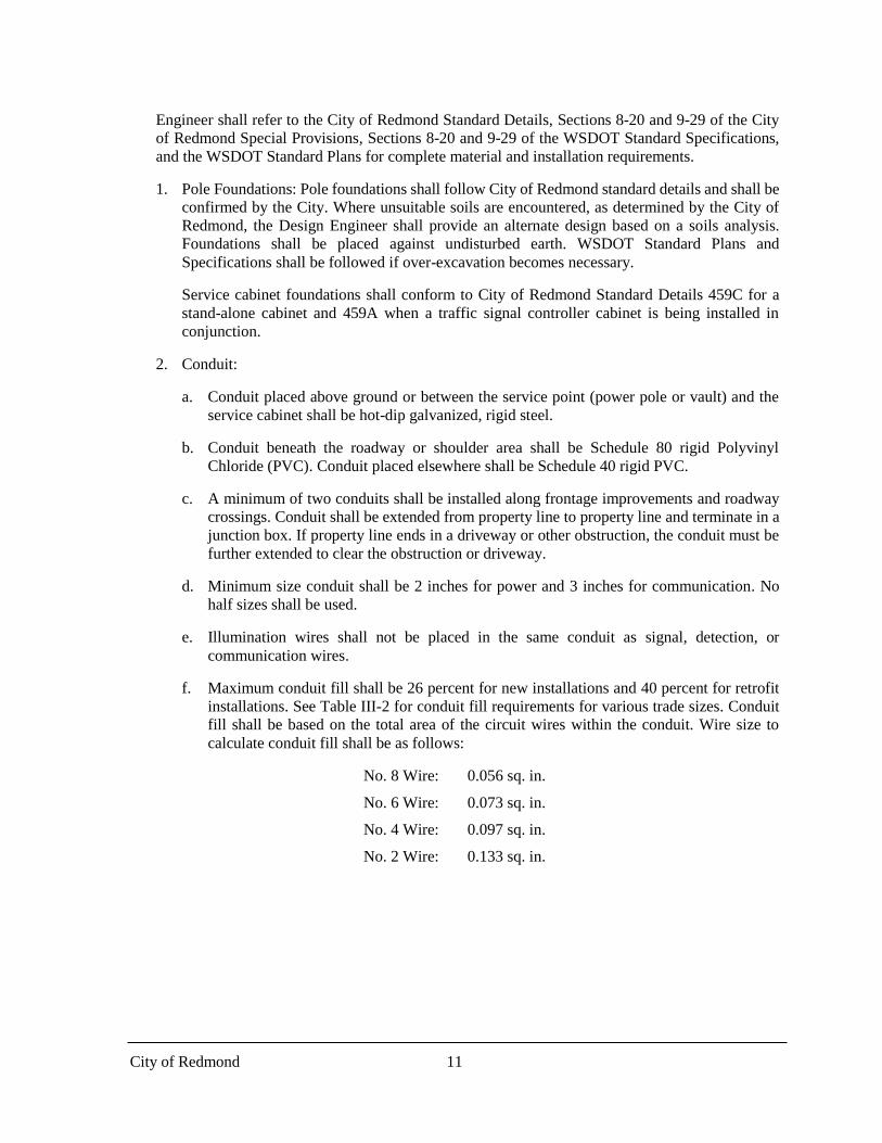
f. Maximum conduit fill shall be 26 percent for new installations and 40 percent for retrofit
installations. See Table III-2 for conduit fill requirements for various trade sizes. Conduit
fill shall be based on the total area of the circuit wires within the conduit. Wire size to
calculate conduit fill shall be as follows:
No. 8 Wire: 0.056 sq. in.
No. 6 Wire: 0.073 sq. in.
No. 4 Wire: 0.097 sq. in.
No. 2 Wire: 0.133 sq. in.

City of Redmond 12
Table III-2. CONDUIT FILL
Trade
Size
Schedule 40 Schedule 80
26 Percent Fill 40 Percent Fill 26 Percent Fill 40 Percent Fill
2” 0.856 sq. in. 1.316sq. in. 0.747sq. in. 1.150sq. in.
3” 1.890 sq. in. 2.907 sq. in. 1.675 sq. in. 2.577 sq. in.
4” 3.264 sq. in. 5.022 sq. in. 2.927 sq. in. 4.503 sq. in.
3. Junction Boxes:
a. Junction box installation shall conform to the City of Redmond Standard Details 462, 464,
467A, 467B and WSDOT Standard Plans.
b. A junction box shall be placed within 10 feet of each luminaire pole as well as adjacent to
the service cabinet. See City of Redmond Standard Detail 420A for typical locations.
c. Junction boxes shall be placed so that no conduit run is greater than 500 linear feet.
d. Junction boxes shall be placed at all locations where the conduit turns 90 degrees or more
horizontally.
e. Junction boxes shall not be located within the traveled way, pedestrian ramps, or
driveways. Junction boxes located in sidewalk or any other Pedestrian Accessible Route
shall have non-slip frames and lids. Junction boxes placed in soft surface must have a
concrete collar per City of Redmond Standard Detail 464.
f. Existing Type 3 junction boxes shall be replaced with new Type 8 junction boxes. All large
junction boxes shall be Type 8, dual lid units.
g. The size of the junction box shall be determined by the total of the conduit diameters
entering the box as follows:
Type 1 Junction Box: Maximum of 6 inches
Type 2 Junction Box: Maximum of 12 inches
Type 4 Junction Box: Maximum of 6 inches
Type 8 Junction Box: Maximum of 24 inches
h. Conduit containing illumination circuits shall not be routed through junction boxes
containing conduit for signal, detection, and/or communication conduits, except where
junction box serves type 3 signal pole.
i. Traceable mule tape must be installed in all empty conduit.

City of Redmond 13
4. Wiring:
a. Main circuit wires shall be sized to provide a maximum of 4 percent voltage drop at the
end of each branch circuit.
b. Minimum wire size shall be No. 8.
c. A ground wire shall be included in all illumination runs and shall be equal in size to the
largest conductor.
d. Circuits from different services shall not enter the same junction box.
5. Service Cabinets:
a. Service cabinets shall conform to City of Redmond Standard Detail 461. Where a
signalized intersection is being constructed in conjunction with the illumination system,
the illumination system may be energized from the service cabinet at the signal.
b. Where the service cabinet is installed to service only an illumination system, it shall be
located near the midpoint of the system to minimize voltage drops.
c. Service cabinets shall power illumination and traffic signals only.
d. All services shall be metered.
e. Services shall be 120/240 volt single phase.
6. Photoelectric Control: All fixtures shall have individual photoelectric cells with a 7-pin
receptacle, and shall incorporate a GE lighting node.
7. Splices and Disconnect Kits: Splices in the junction box to connect the individual luminaires
to the main circuit shall be made with a SEC Connector Company model 1791-DP kit. A fused
quick disconnect kit shall be provided in each pole base, and shall be made with a SEC
Connector Company model 1791-SF
H. Transit Stops: The Design Engineer shall coordinate with transit agencies when any bus stops, park
& ride facilities, or light rail stations are to be illuminated as part of any proposed system. The
following publications provide guidance on illumination requirements for the transit agencies that
operate within the City of Redmond:
1. King County Metro: refer to Metro Transportation Facility Design Guidelines.
2. Sound Transit: refer to Design Standards and Guidelines for Sound Transit Projects: Sounder
& ST Express Passenger Facilities, Chapter 12.
I. Temporary Illumination: A temporary illumination design submittal as part of the submittal
package is required if existing illumination cannot be maintained or is to be removed. Existing
illumination shall not be removed until a temporary system has been approved by the City and is
fully operational. Temporary illumination is also required in the following cases.
1. Replacement of existing illumination system
2. Complex roadway realignment or channelization
3. Multi-lane split around obstruction

City of Redmond 14
4. Temporary traffic signals
5. Night-time pedestrian detour or vehicle detour
6. All intersections with low lighting as determined by the City and traffic control in place
All components of a temporary illumination system shall be crashworthy with breakaway features,
outside the clear zone, or protected from traffic.
The temporary lighting shall satisfy the greater of the “construction lanes and detours” light level
and uniformity ratios in accordance with WSDOT Design Manual Chapter 1040 or the specific
intersection light level and uniformity ratios, as defined in this chapter under Calculation Areas.
All temporary lighting shall be connected to grid power.

APPENDIX A
Roadway Classifications

City of Redmond A-1 Illumination Design Manual
Roadway Classifications1
Principal Arterial Streets
Avondale Road NE (Union Hill Road to Avondale Way)
Avondale Road NE (Avondale Way to Avondale north city limits)
Redmond Way (east city limits to Bear Creek Parkway east)
Bear Creek Parkway (Redmond Way west to Redmond Way east)
Bel-Red Road (NE 20th Street to West Lake Sammamish Parkway)
Redmond Way (west city limits to Bear Creek Parkway west)
Redmond-Woodinville Road – NE 116th Street – NE 124th Street
Redmond-Woodinville Road – NE 90th Street – NE 116th Street
West Lake Sammamish Parkway NE – Bel-Red Road to NE 51st Street
West Lake Sammamish Parkway NE – NE 51st Street to Redmond Way
NE 90th Street – Willows Road to 160th Avenue NE
NE 90th Street – 160th Avenue NE to Red-Wood Road
NE 124th Street – west city limits to Avondale Road
148th Avenue NE – NE 20th Street to Willows Road
154th Avenue NE – West Lake Sammamish Parkway to NE 90th Street
Minor Arterial Streets
NE 20th Street (148th Avenue NE to Bel-Red Road)
NE 24th Street – 148th to Bel-Red Road
152nd Avenue NE (NE 20th Street to NE 31st Street)
Redmond-Woodinville Road (NE 90th Street to Cleveland Street)
Redmond Way (Bear Creek Parkway to 170th Avenue NE)
Avondale Way NE (Avondale Road NE to Redmond Way)
164th Avenue NE Extension (76th Avenue NE to Cleveland Street)
East Lake Sammamish Parkway NE (Redmond Way to 187th Avenue NE)
Leary Way NE (West Lake Sammamish Parkway to NE 80th Street)
NE Union Hill Road (NE to Avondale Way to east city limits)
Novelty Hill Road (east city limits to Avondale Road NE)
Old Redmond Road (west city limits to West Lake Sammamish Parkway)
West Lake Sammamish Parkway NE (Bel-Red Road to south city limits)
Willows Road (Redmond Way to north city limits)
NE 24th Street – city limits to West lake Sammamish Parkway NE
NE 31st/NE 36th Streets (152nd Avenue NE to 156th Avenue NE)
NE 40th Street (west city limits to West Lake Sammamish Parkway)
NE 51st Street (148th Avenue NE to West Lake Sammamish Parkway)
NE 80th Street – Leary Way to 164th Avenue NE
NE 85th Street (154th Avenue NE to 166th Avenue NE)
140th Avenue NE (Redmond Way to south city limits)
156th Avenue NE (NE 51st Street to NE 24th Street)
170th Place NE/Avenue NE (Redmond Way to Avondale Way)
188th Avenue NE – between Union Hill Road and Redmond-Fall City Road

City of Redmond A-2 Illumination Design Manual
Collector Arterial Streets
Cleveland Street (160th Avenue NE to 168th Avenue NE)
NE 27th Street/NE 28th Street (150th Avenue NE to 156th Avenue NE)
NE 60th Street (154th Avenue NE to 156th Avenue NE)
NE 76th Street (Redmond Way to 188th Avenue NE)
NE 79th Street (Redmond Way to Avondale Way NE)
NE 80th Street (132nd Avenue NE to Redmond Way)
NE 80th Street (164th Avenue NE to 169th Avenue NE)
NE 83rd Street (158th Avenue NE to 166th Avenue NE)
NE 104th Street/NE 109th Street (Redmond-Woodinville Road to Avondale Road NE)
NE 110th Street (162nd Avenue NE to 166th Avenue NE)
NE 111th Street (166th Avenue NE to 172nd Avenue NE)
NE 116th Street (Red-Wood Road to Avondale Road NE)
NE 116th Street (Willows Road to 154th Place NE)
31st/36th Street NE (148th Avenue NE to 152nd Avenue NE) (Including Bridge over SR 520)
NE 28th Street (Overlake Access Ramp to 152nd Avenue NE)
150th Avenue NE (NE 36th Street to 51st Street NE)
151st Avenue NE (NE 20th Street to NE 28th Street)
154th Avenue NE (NE 60th Street to Old Redmond Road)
154th Place NE (Red-Wood Road to NE 116th Street)
156th Avenue NE (NE 51st Street to NE 60th Street)
159th Place NE (Bear Creek Parkway to Leary Way)
160th Avenue NE (Redmond Way to Red-Wood Road)
161st Avenue NE (NE 90th to Bear Creek Parkway)
162nd Avenue NE (NE 110th Street to NE 116th Street)
166th Avenue NE (NE 76th Street to 111th Street NE)
169th Avenue NE (NE 79th Street to NE 80th Street)
172nd Avenue NE (West Lake Sammamish Parkway to NE 30th Street)
172nd Avenue NE (NE 111th Street to NE 116th Street)
178th Place NE (Union Hill Road to NE 76th Street)
178th Place NE/180th Avenue NE (NE 76th Street to Union Hill Road)
180th Avenue NE (Redmond Way to NE 76th Street)
185th Avenue NE (Union Hill Road to SR 202/Redmond-Fall City Road)
NE 76th Street (Leary Way to Bear Creek Parkway)
NE 80th Street (169th Avenue NE to 172nd Avenue NE)
168th Avenue NE (Redmond Way to NE 79th Street)
172nd Avenue NE (NE 116th Street to NE 128th Street)
187th Avenue NE (East Lake Sammamish Parkway to SR 202)
192nd Avenue NE (Union Hill Road to NE 65th Street)
Avondale Way (Redmond Way to NE 76th Street)
1As revised in City of Redmond Comprehensive Plan and this Manual.

APPENDIX B
Area Classification Map & Pedestrian Priority Zone Map

BEL-R
ED R
D
BEAR CREEK PKWY
AVON
DALE
RD
NEREDMOND WAY
170th AVE NE
148th
AVE N
E
NE 90th ST
NE 124th ST
W LK SAMMAMISH PKWY
148th
AVE N
E
RED-
WOOD
RD
NE
154th AVE NE
BEL-RED RD
AVON
DALE
RDNE
148th AVE NE
RED-WOOD RD NE
REDMOND WAY
REDMOND WAY154th
AVE N
E
NE 109th ST
156th
AVE N
E
172n
d AVE
NE
NE 80th ST
NE 110th ST
171s
tAVE
NE
NE 20th ST
NE 100th ST
NE 36th ST
NE 76th ST
162n
d AVE
NE
NE 80th ST
180th
AVE N
E
172n
d AVE
NE
NE 116th ST
180th
AVE N
E
171s
t AVE
NE
166th
AVE N
E
NE 79th ST
NE 111th ST
CLEVELAND ST
NE 104th ST
161 s
tAVE
NE1 6
0thA V
ENE
NE 83rd ST
NE 31st ST
NE 70th ST
NE 60th ST
178th PL NE159th PL NE
NE 67th CT
152n
d AVE
NE
NE 65th ST18
8th AV
E NE
185th
AVE N
E
150th
AVE N
E
154th PLNE
NE 116th ST
140 th
AVE
NE
NE 30th ST NE 30th ST
NE 132nd ST
NE 24th ST
NE 100th ST
NE 80th ST
NE 132nd ST
132n
d AV E
N E
173rd
AVEN
E
NE 14th ST
NE 40th ST
NE 28th ST
130th
AVEN
E1 3
0 thAV
EN E
172n
dAV E
N E
NE 40th ST
134 th
AVEN
E
172n
d AVE
NE
164 th
A VE N
E
168th
AVEN
E
NE 50th ST
132 n
dAV E
N E
NE 75th ST
NE 125th ST
130th AVENE
1 32 n
d AVE
NE
NE 28th ST
NE 14th ST
NE 16th ST
134t h
A VE
NE
NE 32 nd ST
156t h
A VE
NE
NE 16th ST
NE 12t hS T
162n
d AVE
N E
NE 132nd ST
NE BELLEVUE REDMOND RD
NE 50th ST
130thPL NE
NE 47th ST
NE 51st PL
NE 24th ST
164th
AVE
N E
162 n
d AVE
NE
NE 124th ST
NE 104th ST
NE 20th ST
SLAT
ERAVE NE
NE 45th ST
172n
dPL N
E
NE 4 2 ndST
NE 60th ST
180th
AVEN
E
1 68 th
AVE N
E
NE 51 st ST
NE 14th ST
164th
AVE
NE NE 132nd ST
NE 85th ST
168th
A VE N
E
1 96th
AVE
NE
NE 20th ST
196th
AVEN
E19
6 thA V
ENE
NE 28th ST
130th AVE NE
156th
A VE N
E
NE 116th ST
G:\GI
S\Work
Orders
\Public
Works
\16089
8llumin
ationC
reateM
ap_Ad
nanS\G
IS\Illu
minatio
nDesi
gn_Fin
al.mxd
I
City of Redmond - Area Classification Map
Lake Sammamish
Samm
amish
Rive
r
Open Space
Open Space
Illumination Design ManualPublished October 2018
520
202
202
Area Classifications
Old TownOverlake Village
Parks
ResidentialCBD
City Limits
Commercial
OBATMarymoor Subarea

Chapter 4.3: Pedestrian System Plan
81
Figure 39. Pedestrian priority zones
Pedestrian Priority Zones
N
Marymoor Park
Overlake
SE Redmond
Education Hill
Idylwood
Grass Lawn
North Redmond
Willows / Rose Hill
Downtown
Bear Creek
Sammamish Valley
Lake S
amm
amish
148th
AV
E N
E
REDMO
ND WAY
NE 40th ST
WIL
LO
WS R
D N
E
W L
K S
AM
MA
MISH
PK
WY
156th
AV
E N
E
AV
ON
DA
LE R
D N
E
RED
-WO
OD
RD
NE
188th
AV
E N
E
NE 51st ST
140th
AV
E N
E
NE 90th ST
BEL-
RED
RD
UNION HILL RD
OLD REDMOND RD
NE 85th ST
154th
AV
E N
E
LEARY WAY
164th
AV
E N
E
NE 24th ST
BEAR CREEK PKWY
E L
K S
AM
MA
MIS
H P
KW
Y
NE 70th St
AVO
ND
ALE W
AY N
E
NE 68th St
NE 67th St
NE 124th ST
BEL-R
ED
RD
NE 24th ST
¯
Pedestrian Priority Zones
0 10.5 Miles
Pedestrian Priority Zones
Neighborhoods
Waterbodies
City Limit

APPENDIX C
Illumination Plan Checklist

Illumination Design Manual Appendix C City of Redmond
Illumination Plan Checklist
As a minimum, the following shall be included on an illumination plan submittal:
Cover Sheet If the illumination design is a stand-alone project, the plans shall include a cover sheet. If the illumination
design is a part of a larger plan set, a separate cover sheet for the illumination portion is not necessary. When
used, the cover sheet shall include the following as a minimum:
INITIAL & FINAL
1. City of Redmond project name and number including scale, stationing, and north arrow
2. Vicinity map showing the project area and surrounding road system (up to an approximate
five-block radius)
3. Sheet index showing illumination design page number
4. Legend of existing and proposed items drafted in accordance with American Public Works
Association (APWA) standards and symbols
If a cover sheet is not required, the legend shall be included on the plan sheet
5. A standard City of Redmond construction signature block, including the City logo Plan Sheet(s) All existing features shall be shown in 50% screened gray scale and all proposed features shall be shown in bold.
Where the roadways are straight, two sections in “plan/plan” format may be included on a single sheet. As a
minimum, plan sheets shall contain the following:
INITIAL FINAL
1. A minimum scale of 1 inch = 40ft
Exception: A minimum scale of 1 inch = 20ft may be used if it makes half-size sheets
more clear and easy to interpret
2. North arrow, oriented up or to the right
3. Scale bar
4. Street names
5. Location of the proposed poles with station and offset
6. Location of conduit, junction boxes, transformers, and service cabinets with station and
offset
7. Construction centerline with stationing
8. Right-of-way and easements
9. Underground and overhead utilities, both proposed and existing to remain
10. Curb, sidewalks, and lane lines, both proposed and existing to remain
11. Driveways
12. Retaining structures
13. Reference to the sheet that contains the construction notes, conduit/wire schedule, pole
schedule, and any other items referenced on the plan sheet, if provided on a separate sheet

Illumination Design Manual Appendix C City of Redmond
INITIAL FINAL
14. A City of Redmond construction signature block
APPROVED FOR CONSTRUCTION
___________________________________
FOR: Martin Pastucha, P.E.
Director of Public Works
City of Redmond
Date: ______________________________
Plan Chk Engr_______________________
Storm: _____________________________
Utility: _____________________________
Fire _______________________________
Trans / Engr: ________________________
Planning: ___________________________
This approval is for the design concept only. These plans
appear to be in conformance with the City Of Redmond
design standards for construction. This approval shall not
be construed as authorizing construction not in accordance
with applicable City standards. The City reserves the right
to require revisions to the approved plans to assure
conformance with City of Redmond design standards for
construction at any time that it is discovered that the
proposed construction does not otherwise meet the
applicable construction standards. The owner is required
to provide designs and plans in accordance with applicable
City standards and assures that construction is
accomplished in accordance with those standards. The
owner and/or design engineer and/or developer may be
required to make necessary approved field revisions to
correct any errors or omissions found on the approved
plan.
15. Include note that the Electrical Contractor shall obtain a City of Redmond Electrical
Permit for work in the right-of-way before commencing any work. All work shall conform
to the City of Redmond Standard Details and Specifications, these plans and the latest
edition to the National Electrical Code.
16. The name, phone, number, and address of the design firm completing the lighting plans
Notes, Schedules, Detail Sheet(s)
When notes, schedules and detail cannot be clearly and conveniently shown on the plan sheets, they shall be
included on a separate sheet.
INITIAL FINAL
1. General Notes: General notes to accompany all projects shall include, but not be limited
to, the following:
• All conduit shall be installed by open trench unless otherwise indicated on the plans
• Proposed junction boxes must be ground and bonded, per NEC. All existing junction boxes
within the project limits shall also be ground and bonded per NEC. Any junction boxes in
soft surface must have a concrete collar per City of Redmond Standard Detail 464
2. Construction Notes: Construction notes shall include, but not be limited to, the following:
• Pole and foundation installation including specifying installation of below grade anchor
bolts and base plates for poles requiring subsurface foundation.
• Service cabinet and foundation installation
• Any non-standard junction box installation
• Connection to the power source
• Removal of existing equipment
• Special conduit installation such as boring or installation on structures

Illumination Design Manual Appendix C City of Redmond
INITIAL FINAL
3. Pole Schedule: A Pole Schedule shall be included with all projects and shall contain as
a minimum the following information:
• Pole station and offset from construction centerline (provide northing and easting if
centerline stationing is not feasible).
• Foundation diameter and depth if non-standard installation
• Specify fixed or breakaway pole base
• Pole and Luminaire type (combination pole and luminaire as noted in Item 4 below)
• Detail reference (special foundation, pads, special installation, etc.)
• Luminaire arm length
• Luminaire mounting height
• Luminaire type, wattage, distribution pattern, and lumen value.
• Indicate whether the system is City owned or Intolight owned
• Other information as required for clarity
4. If multiple units are being used, the following legend shall be placed as applicable adjacent
to the Pole Schedule:
Square Concrete: Square concrete pole with cree ledway fixture per City of Redmond
Standard Detail 420
Octagonal Concrete: Octagonal concrete pole with cobra head fixture on a mast arm per
City of Redmond Standard Detail 430
J -Series Round Steel: Round steel pole, 5-foot 9-inch radius davit with cobra-head fixture
on a mast arm per City of Redmond Standard Detail 425 and WSDOT standard plans
Victorian Steel: Fourteen-foot-high Victorian style steel pole with pole top mounted
decorative style luminaire per City of Redmond Standard Detail 471
Fluted Steel: Hanging decorative luminaire on fluted decorative steel pole per City of
Redmond Standard Detail 470
Victorian Concrete: Twelve- to fifteen-foot-high Victorian style concrete pole with pole
top mounted decorative style luminaire per City of Redmond Standard Detail 430B
Round steel: Twenty-eight-foot-high round steel pole with Curvilinear fixture per City of
Redmond Standard Detail 487
Pedestrian Round Steel: Ten-foot-high round steel pole with kim bounce single-decorative
luminaire per City of Redmond Standard Detail 488.
5. Wire/Conduit Schedule: A wire/conduit schedule shall be included with all projects and
shall include as a minimum the following information:
• Run identification number
• Size and type of material of conduit
• Size and number of conductors
• Circuit number
• Percent fill for each conduit
• Communication spare conduits end in Type 2 junction boxes

Illumination Design Manual Appendix C City of Redmond
INITIAL FINAL
6. Breaker/Contactor Schedule: Main breaker, branch breakers, and contactor sizes shall be
identified if different from the standard cabinet requirements identified on the City of
Redmond Standard Detail 461
7. Details: Details shall include, but not be limited to, the following:
• Pads around the pole base and junction box
• Installation on structures and installations near or in conjunction with retaining structures
• Service connection and service application address
• Service connection requirements
• Service cabinet foundation (for a standalone installation) located by station and offset.
Where the service cabinet is located at a signalized intersection and services the
intersection signal, it shall be located and described on the signal plan.
• Trench and backfill including pavement restoration
8. Single Line Wiring Schematic Detail shall be included and shall contain the following
information:
• Luminaires, junction boxes, and service cabinets (both existing and proposed) shall be
shown in their relative location to one another, but does not need to be to any particular
scale.
• Different Luminaire Type Units shall be shown by different symbols
• Individual circuits shall be clearly labeled
• A legend shall be included on the sheet to identify all symbols used on the diagram
• Street names and a north arrow shall be included
Supporting Calculations The following information must be included in the submittal package:
INITIAL FINAL
1. Th e AGi32 software output (graphical figure) shall be plotted at a legible resolution and
include the following design details:
• Pole spacing
• System layout
• Calculated average maintained illumination level in horizontal foot-candles (Hfc) with a
five-foot max gradient and Iso lines turned on
• Calculated uniformity ratio (UR) for Average:Minimum illumination
• Design average maintained illumination level in Hfc per Appendix D
• Design uniformity ratio for Average:Minimum illumination per Appendix D
• Luminaire mounting height
• Luminaire part number
• Luminaire type
• Luminaire wattage
• Luminaire lumen output and color temperature (For LED Fixtures)
• Light Loss Factor(LLF)

Illumination Design Manual Appendix C City of Redmond
INITIAL
FINAL
2. System Calculations:
• Line Loss for a 4% maximum voltage drop and a No. 8 minimum wire size
• Breaker sizing
3. If potholing was conducted, then submit pothole data showing depth and location of
existing utilities.

APPENDIX D
Illuminance Method Design Criteria

Table 1-D. Illuminance Method Design Criteria
Roadway9
RO
AD
WA
Y1
CL
AS
SIF
ICA
TIO
N
Area Classification2 Target Light Levels
Luminaire Mounting
Height
Maximum Arm
Length Maximum Wattage8
City Standard
Detail Fixture5,7 Pole5
Maintained Average (fc)
Uniformity Ratio
(Avg/Min)
P
RIN
CIP
AL
AR
TE
RIA
L
Commercial 1.2 3:1 40 16 271 425 cobra head J -series round steel
Residential 0.8 3:1 404 16 271
425 cobra head J -series round steel 353 12 183
CBD 1.2 3:1 35 4 182 420 cree ledway square concrete
12-15 n/a 112 430B decorative post top victorian concrete
Old Town 1.2 3:1 35 8 112 470 decorative hanging fluted steel
14 n/a 88 471 decorative post top victorian steel
OBAT 1.2 3:1 35 12 271 430 cobra head octagonal concrete
14 n/a 88 488 kim bounce pedestrian round steel
Overlake Village 1.2 3:1 40 4 271 487 curvilinear round steel
14 n/a 88 488 kim bounce pedestrian round steel
Marymoor Subarea 1.2 3:1 35 12 271 430 cobra head octagonal concrete
14 n/a 88 488 kim bounce pedestrian round steel
MIN
OR
AR
TE
RIA
L
Commercial 1.0 3:1 35 16 271 425 cobra head J -series round steel
Residential 0.6 4:1 35 164 271
430 cobra head octagonal concrete 35 123 183
CBD 1.0 3:1 35 4 182 420 cree ledway square concrete
12-15 n/a 112 430B decorative post top victorian concrete
Old Town 1.0 3:1 35 8 112 470 decorative hanging Fluted steel
14 n/a 88 471 decorative post top victorian steel
OBAT 1.0 3:1 35 12 271 430 cobra head octagonal concrete
14 n/a 88 488 kim bounce pedestrian round steel
Overlake Village 1.0 3:1 35 4 271 487 curvilinear round steel
14 n/a 88 488 kim bounce pedestrian round steel
Marymoor Subarea 1.0 3:1 35 12 271 430 cobra head octagonal concrete
14 n/a 88 488 kim bounce pedestrian round steel

RO
AD
WA
Y1
CL
AS
SIF
ICA
TIO
N
Area Classification2
Target Light Levels Luminaire Mounting
Height
Maximum Arm
Length
Maximum Wattage8
City Standard
Detail Fixture5,7 Pole5
Maintained Average (fc)
Uniformity Ratio
(Avg/Min)
CO
LL
EC
TO
R A
RT
ER
IAL
Commercial 0.8 4:1 35 12 271 425 cobra head J -series round steel
Residential 0.6 4:1 35 12 135 430 cobra head octagonal concrete
CBD 0.8 4:1 35 4 182 420 cree ledway square concrete
12-15 n/a 112 430B decorative post top victorian concrete
Old Town 0.8 4:1 35 8 112 470 decorative hanging fluted steel
14 n/a 88 471 decorative post top victorian steel
OBAT 0.8 4:1 35 12 271 430 cobra head octagonal concrete
14 n/a 88 488 kim bounce pedestrian round steel
Overlake Village 0.8 4:1 35 4 271 487 curvilinear round steel
14 n/a 88 488 kim bounce pedestrian round steel
Marymoor Subarea 0.8 4:1 35 12 271 430 cobra head octagonal concrete
14 n/a 88 488 kim bounce pedestrian round steel
LO
CA
L A
CC
ES
S6
Commercial 0.8 4:1 35 12 271 425 cobra head J -series round steel
Residential 0.4 6:1 25 12 92 430 cobra head11 octagonal concrete
Decision Point Lighting10 12-15 n/a 112 430B decorative post top victorian concrete
CBD 0.8 4:1 35 4 182 420 cree ledway square concrete
12-15 n/a 112 430B decorative post top victorian concrete
Old Town 0.8 4:1 35 8 112 470 decorative hanging fluted steel
14 n/a 88 471 decorative post top victorian steel
OBAT 0.8 4:1 35 12 271 430 cobra head octagonal concrete
14 n/a 88 488 kim bounce pedestrian round steel
Overlake Village 0.8 4:1 35 4 271 487 curvilinear round steel
14 n/a 88 488 kim bounce pedestrian round steel
Marymoor Subarea 0.8 4:1 35 12 271 430 cobra head octagonal concrete
14 n/a 88 488 kim bounce pedestrian round steel

1. See Table 1-A in Appendix A. 2. See area classification map in Appendix B. 3. Use for roadway width of 36ft or less 4. Use for roadway width over 36ft 5. See Sections 9-29.6 and 9-29.10 of the City of Redmond Special Provisions for complete pole and luminaire specifications. 6. Poles and luminaires on Local Access roadways in all areas except the CBD shall be owned, installed, and operated by Puget Sound Energy. 7. The light distribution pattern must be Type III, unless approved otherwise by the City of Redmond. 8. Maximum wattage values are for LED fixtures only. Coordinate with City of Redmond for High Pressure Sodium and Metal Halide maximum wattage values. 9. See the Design Guidelines section of the design manual for direction on pedestrian facility and intersection illumination criteria. 10. Decision Point Lighting may be applied to residential local access streets with 300 ft maximum spacing between luminaires. Luminaires are placed at intersections, crossings, changes in roadway geometry, dead
ends, hazards, etc. Luminaires must be cobra head fixtures at 25ft mounting height. 11. GE Evolve fixtures and post tops by special request only.

APPENDIX E
Streetlight Requirement Worksheet

O:\Gloria M\Web Updates\PREP Streetlight Requirement Worksheet 151124.docx
CITY OF REDMOND STREETLIGHT REQUIREMENT WORKSHEET
This worksheet is to be filled and submitted by the applicant in the 30% Pre Review Entitlement Process
(PREP) Formal Process to evaluate the illumination system requirements of the project.
Please review the City of Redmond Illumination Design Manual
(http://www.redmond.gov/common/pages/UserFile.aspx?fileId=159261) and complete the entire form
and return it to the Redmond Engineering Services Division as part of the 30% PREP submittal.
1. Applicant name and address:
2. Property location:
a. Property address:
b. Development name:
c. Assessor’s Parcel Number(s):
Street Frontage(s):
3. Roadway Classification:
4. Area Land-Use:
Existing
Proposed
a. Ownership: (COR or PSE)
b. Light Level (fc):
c. Uniformity (avg/min):
d. Pole Type:
e. Fixture Type:
f. Ownership (COR or PSE):
h. Light Level (fc):
i. Uniformity (avg/min):
j. Pole Type:
k. Fixture Type:
Signature of Street Lighting Engineer: Date:
For Official Use Only:
Applicant has submitted a completed worksheet: ___________________ __________________ Initials Date
Streetlighting Requirements Met: □ Yes □ No
*Note: This worksheet is for Street Lighting Analysis in the ROW and not for on site