Illumination Aesthetics: Light as a Creative Material ... · Illumination Aesthetics: Light as a...
12
Illumination Aesthetics: Light as a Creative Material within Computational Design Cesar Torres, Jasper O’Leary, Molly Nicholas, Eric Paulos Electrical Engineering and Computer Sciences University of California, Berkeley {cearto, j.oleary, molecule, paulos}@berkeley.edu B C A N Figure 1. a) an illuminated hairpin (1 led); a tactile flexible diffuser cast with small glass beads creates diffusion and shadow, b) a sun-moon light art piece (25 leds); a computationally generated reflector controls light rays to form soft and hard edges to blend colored lights, c) a dynamic tactile map of an urban center (16 leds); volumetric diffusers indicate building locations; buildings light up in succession to indicate pathways. ABSTRACT Recent digital fabrication tools have enabled new form-giving using a wide range of physical materials. However, light as a first class creative material has been largely ignored within the design of our electronic objects. Our work expands the illumination design space by treating light as a physical material. We introduce a digital design tool that simulates and visualizes physical light interactions with a variety of materials for creating custom luminaires. We further develop a computational design and fabrication process for creating custom secondary optics elements (SOEs), which provides additional handles for users to physically shape and redirect light to compose, fill, and evenly diffuse planar and volumetric geometries. Through a workshop study with novice electronic designers, we show how incorporating physical techniques to shape light alters how users view the role and function of LEDs and electronics. We produce example pieces that showcase how our approach expands the electronics aesthetic and discuss how viewing light as material can engender novel, expressive artifacts. Author Keywords New Media; displays; lighting; luminaire; digital fabrication Permission to make digital or hard copies of part or all of this work for personal or classroom use is granted without fee provided that copies are not made or distributed for profit or commercial advantage and that copies bear this notice and the full citation on the first page. Copyrights for third-party components of this work must be honored. For all other uses, contact the Owner/Author. Copyright is held by the owner/author(s). CHI 2017, May 06–11, 2017, Denver, CO, USA ACM 978-1-4503-4655-9/17/05. http://dx.doi.org/10.1145/3025453.3025466 ACM Classification Keywords H.5.m. Information interfaces and presentation: User Inter- faces - Interaction Styles; D.2.2 Design Tools and Techniques: User interfaces INTRODUCTION Light is a rich, expressive medium that has enabled a tremen- dous amount of creativity and innovation in engineering, art, and design. This design space is quickly evolving with the introduction of smart Light Emitting Diodes (LEDs) (e.g. NeoPixels, dotStars) and electroluminescent materials (e.g. EL wire, OLED). These components are becoming easier to program, attach, and control, supporting a new ecology of devices appearing in increasingly diverse contexts and uses. However, most of these fundamental lighting elements were never intended to be used within such designs. In fact most manufactured electronic lighting components are produced for architectural lighting (39%), display backlighting (18%), and commercial signage (12%) [1]. Even worse, the most preva- lent LED form-factors constrain the LED to the characteristic electronic point-light aesthetic. For many electronic projects, this limits the function of LEDs to simple status indicators. Even as the cost of the LED shrinks, the role, function, and control of LEDs in electronic devices has remained limited to blinking, flashing, and color changing via digital manipula- tion. The physical properties of the LED and light get omitted from the design conversation which unfortunately almost com- pletely ignores the rich, expressive value that light can play when treated as a material. How might we expand the different expressions of light and the LED to enable new Illumination Aesthetics — the expansion of light manipulation techniques to produce novel visual effects, Explorative Engineering CHI 2017, May 6–11, 2017, Denver, CO, USA 6111
Transcript of Illumination Aesthetics: Light as a Creative Material ... · Illumination Aesthetics: Light as a...

Illumination Aesthetics: Light as a Creative Material withinComputational Design
Cesar Torres, Jasper O’Leary, Molly Nicholas, Eric PaulosElectrical Engineering and Computer Sciences
University of California, Berkeley{cearto, j.oleary, molecule, paulos}@berkeley.edu
B CA
N
Figure 1. a) an illuminated hairpin (1 led); a tactile flexible diffuser cast with small glass beads creates diffusion and shadow, b) a sun-moon light artpiece (25 leds); a computationally generated reflector controls light rays to form soft and hard edges to blend colored lights, c) a dynamic tactile map ofan urban center (16 leds); volumetric diffusers indicate building locations; buildings light up in succession to indicate pathways.
ABSTRACTRecent digital fabrication tools have enabled new form-givingusing a wide range of physical materials. However, lightas a first class creative material has been largely ignoredwithin the design of our electronic objects. Our work expandsthe illumination design space by treating light as a physicalmaterial. We introduce a digital design tool that simulatesand visualizes physical light interactions with a variety ofmaterials for creating custom luminaires. We further developa computational design and fabrication process for creatingcustom secondary optics elements (SOEs), which providesadditional handles for users to physically shape and redirectlight to compose, fill, and evenly diffuse planar and volumetricgeometries. Through a workshop study with novice electronicdesigners, we show how incorporating physical techniquesto shape light alters how users view the role and functionof LEDs and electronics. We produce example pieces thatshowcase how our approach expands the electronics aestheticand discuss how viewing light as material can engender novel,expressive artifacts.
Author KeywordsNew Media; displays; lighting; luminaire; digital fabrication
Permission to make digital or hard copies of part or all of this work for personal orclassroom use is granted without fee provided that copies are not made or distributedfor profit or commercial advantage and that copies bear this notice and the full citationon the first page. Copyrights for third-party components of this work must be honored.For all other uses, contact the Owner/Author.Copyright is held by the owner/author(s).CHI 2017, May 06–11, 2017, Denver, CO, USAACM 978-1-4503-4655-9/17/05.http://dx.doi.org/10.1145/3025453.3025466
ACM Classification KeywordsH.5.m. Information interfaces and presentation: User Inter-faces - Interaction Styles; D.2.2 Design Tools and Techniques:User interfaces
INTRODUCTIONLight is a rich, expressive medium that has enabled a tremen-dous amount of creativity and innovation in engineering, art,and design. This design space is quickly evolving with theintroduction of smart Light Emitting Diodes (LEDs) (e.g.NeoPixels, dotStars) and electroluminescent materials (e.g.EL wire, OLED). These components are becoming easier toprogram, attach, and control, supporting a new ecology ofdevices appearing in increasingly diverse contexts and uses.However, most of these fundamental lighting elements werenever intended to be used within such designs. In fact mostmanufactured electronic lighting components are produced forarchitectural lighting (39%), display backlighting (18%), andcommercial signage (12%) [1]. Even worse, the most preva-lent LED form-factors constrain the LED to the characteristicelectronic point-light aesthetic. For many electronic projects,this limits the function of LEDs to simple status indicators.Even as the cost of the LED shrinks, the role, function, andcontrol of LEDs in electronic devices has remained limitedto blinking, flashing, and color changing via digital manipula-tion. The physical properties of the LED and light get omittedfrom the design conversation which unfortunately almost com-pletely ignores the rich, expressive value that light can playwhen treated as a material.
How might we expand the different expressions of light and theLED to enable new Illumination Aesthetics — the expansion oflight manipulation techniques to produce novel visual effects,
Explorative Engineering CHI 2017, May 6–11, 2017, Denver, CO, USA
6111

FRONTEND ILLUMINATION DESIGN TOOL
TARGET GEOMETRY
REFLECTOR
DIFFUSER
LIGHT SOURCE
TARGET
INPUT
OPTIMIZED REFLECTOR
COMPUTATIONAL DESIGN BACKEND
FABRICATION PIPELINE
Parametric OptimizationTARGET BEAM PLANE
ANNOTATED SVG
HARD EDGESOFT EDGE
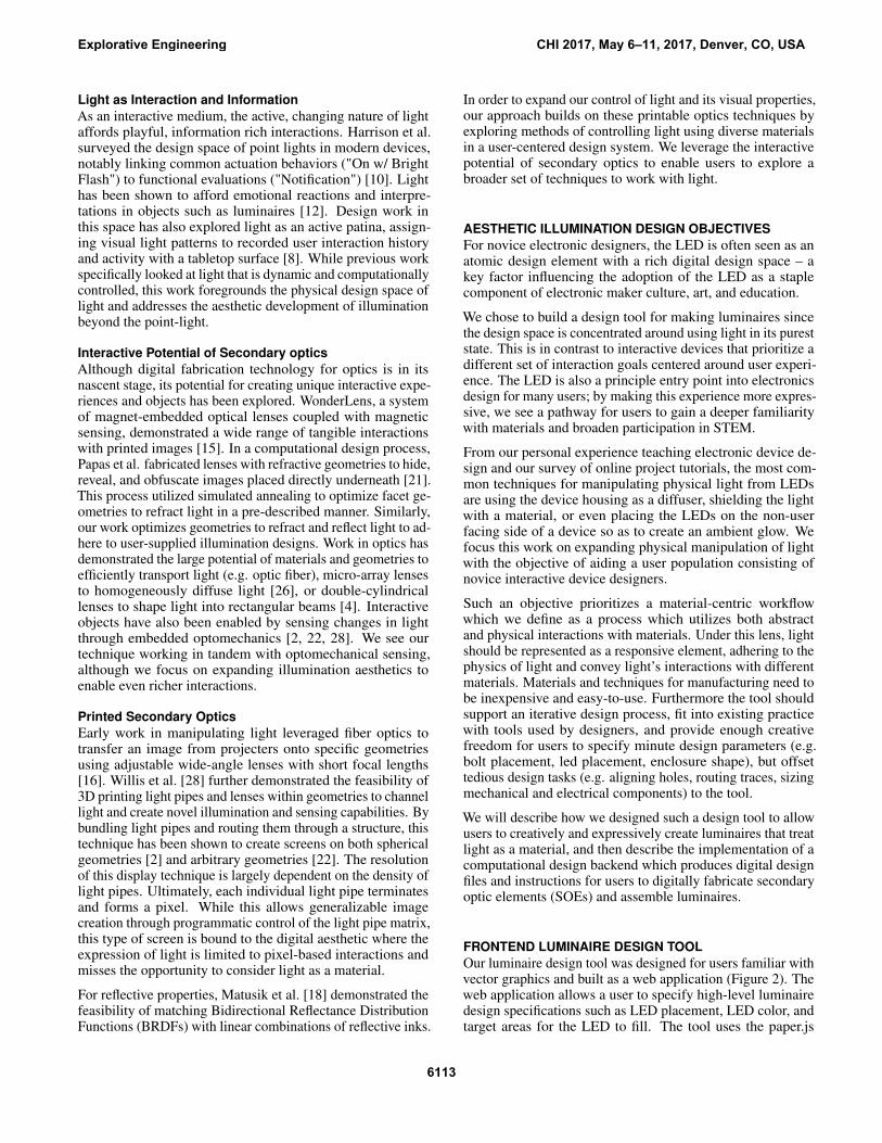
Figure 2. Luminaire Creation Pipeline. a) Given an SVG graphic, our luminaire design tool aids users with laying out LEDs, visualizing light interac-tions, and specifying target areas to fill with light. In the callout, an LED is specified to fill a moon-shape. b) A computational design backend generatesan optimal secondary optics system to achieve the desired design using ray tracing to guide a simulated annealing search. All files for 3D printinggeometries and milling circuits are produced by the backend, c) an instruction set guides the user to assemble the luminaire.
sensations, and interactions? Lighting designer Brad Hindsonsuggests four concepts for envisioning light as a material: lightas sharp and diffuse, light as refractive and reflective, light asshadow creator, and light as dynamic element [11]. Howeverwithin this expressive design landscape we lack accessibletools to readily manipulate and creatively form light.
In order to foreground light as an equal actor with other physi-cal materials, this work develops techniques for creatively andcomputationally designing and fabricating secondary optics el-ements (SOEs). SOEs such as reflectors, diffusers, and lensesare commonly used to manipulate light emitted from a sourcesuch as an LED. Such secondary optics are commonly usedin the lighting industry for applications like collimating LEDrays to extend the distance a bicycle headlamp can travel, orfor combining beams from multiple light sources to appearas one. However techniques for making, purchasing, or con-figuring appropriate materials to control light remains a tacitpractice. This work aims to provide an accessible, general-izable fabrication technique for creating secondary optics toempower users to control and manipulate light and expand theelectronic aesthetic.
To explore Illumination Aesthetics, we constructed a pipelinefor creating luminaires — a device that produces, controls,and distributes light. The Illuminating Engineering Society(IES) [13] defines luminaires as consisting of: one or morelamps or LEDs, optical devices designed to distribute light,sockets for supplying electric power, and the mechanical com-ponents required to support or attach the housing.
Specifically, in this paper we present two contributions:
• A novel and accessible luminaire design tool for use by non-expert electronic designers to visually design, simulate, andfabricate non-trivial illumination within physical objects.• A computational design pipeline comprising the entire phys-
ical, electronic, and optical design of materials necessary tofabricate and realize the final desired luminaire.
We evaluated the design tool in a formal user study whereparticipants designed their own luminaire. Each of the partici-pant’s luminaires were fabricated and used to gauge percep-tions of the function and aesthetic of LEDs with the expanded
abilities of our technique. Furthermore, through a set of ex-ample luminaires (Figure 1), we show how this fabricationtechnique enables a novel set of interactive interfaces whichplace light as a prime citizen in design.
RELATED WORKDiverse communities have explored the potential of light andoptics for creating interactive, aesthetically pleasing, and sens-ing artifacts. Below, we describe work that explores light as aphysical material and medium.
Light as MediumThere exists a large body of work within the arts and de-sign community that utilized light as an artistic medium, ex-ploring material-specific optic properties to create engaging,critical work. Utilizing projected light, James Turrell influ-ences a viewer’s depth perception by simulating 3D formson 2D spaces (Shallow Space Constructions) [27]. In Ex-ploded Views, Jim Campbell creates three-dimensional ani-mated shadows by controlling the intensity of several lightsources suspended in a dense irregular grid [3]. Utilizing thesubtle reflective properties of wood, Daniel Rozin’s WoodenMirror actuated a grid of small wooden “pixels” to differentorientations to create changes in value and form images [25].Eliasson’s The Weather Project made use of light’s refractivequalities, adding a fine mist to materialize moving weatherformations indoors [6]. Notably, these works demonstrate amaterial and space-driven exploration of light.
Dynamic light has been explored in early work such as LászlóMoholy-Nagy’s Light-Space Modulator which spun reflectivegeometries to create visceral moving light installations [19].Through long-exposure photography, the persistence of lightwas captured as a drawing and painting medium in influentialworks like Gjon Mili’s Picasso draws a centaur [9]. Lighthas also been explored conceptually; most well known in thisspace, Dan Flavin created light objects that function as systemsof investigation [7]. Pierce et al. further described otherphenomenological dimensions of light in electronic objects astied to the object, its material, and its source [23]. Our workparticularly explores the design dimensions of illuminationafforded through the optical manipulation of light.
Explorative Engineering CHI 2017, May 6–11, 2017, Denver, CO, USA
6112
Light as Interaction and InformationAs an interactive medium, the active, changing nature of lightaffords playful, information rich interactions. Harrison et al.surveyed the design space of point lights in modern devices,notably linking common actuation behaviors ("On w/ BrightFlash") to functional evaluations ("Notification") [10]. Lighthas been shown to afford emotional reactions and interpre-tations in objects such as luminaires [12]. Design work inthis space has also explored light as an active patina, assign-ing visual light patterns to recorded user interaction historyand activity with a tabletop surface [8]. While previous workspecifically looked at light that is dynamic and computationallycontrolled, this work foregrounds the physical design space oflight and addresses the aesthetic development of illuminationbeyond the point-light.
Interactive Potential of Secondary opticsAlthough digital fabrication technology for optics is in itsnascent stage, its potential for creating unique interactive expe-riences and objects has been explored. WonderLens, a systemof magnet-embedded optical lenses coupled with magneticsensing, demonstrated a wide range of tangible interactionswith printed images [15]. In a computational design process,Papas et al. fabricated lenses with refractive geometries to hide,reveal, and obfuscate images placed directly underneath [21].This process utilized simulated annealing to optimize facet ge-ometries to refract light in a pre-described manner. Similarly,our work optimizes geometries to refract and reflect light to ad-here to user-supplied illumination designs. Work in optics hasdemonstrated the large potential of materials and geometries toefficiently transport light (e.g. optic fiber), micro-array lensesto homogeneously diffuse light [26], or double-cylindricallenses to shape light into rectangular beams [4]. Interactiveobjects have also been enabled by sensing changes in lightthrough embedded optomechanics [2, 22, 28]. We see ourtechnique working in tandem with optomechanical sensing,although we focus on expanding illumination aesthetics toenable even richer interactions.
Printed Secondary OpticsEarly work in manipulating light leveraged fiber optics totransfer an image from projecters onto specific geometriesusing adjustable wide-angle lenses with short focal lengths[16]. Willis et al. [28] further demonstrated the feasibility of3D printing light pipes and lenses within geometries to channellight and create novel illumination and sensing capabilities. Bybundling light pipes and routing them through a structure, thistechnique has been shown to create screens on both sphericalgeometries [2] and arbitrary geometries [22]. The resolutionof this display technique is largely dependent on the density oflight pipes. Ultimately, each individual light pipe terminatesand forms a pixel. While this allows generalizable imagecreation through programmatic control of the light pipe matrix,this type of screen is bound to the digital aesthetic where theexpression of light is limited to pixel-based interactions andmisses the opportunity to consider light as a material.
For reflective properties, Matusik et al. [18] demonstrated thefeasibility of matching Bidirectional Reflectance DistributionFunctions (BRDFs) with linear combinations of reflective inks.
In order to expand our control of light and its visual properties,our approach builds on these printable optics techniques byexploring methods of controlling light using diverse materialsin a user-centered design system. We leverage the interactivepotential of secondary optics to enable users to explore abroader set of techniques to work with light.
AESTHETIC ILLUMINATION DESIGN OBJECTIVESFor novice electronic designers, the LED is often seen as anatomic design element with a rich digital design space – akey factor influencing the adoption of the LED as a staplecomponent of electronic maker culture, art, and education.
We chose to build a design tool for making luminaires sincethe design space is concentrated around using light in its pureststate. This is in contrast to interactive devices that prioritize adifferent set of interaction goals centered around user experi-ence. The LED is also a principle entry point into electronicsdesign for many users; by making this experience more expres-sive, we see a pathway for users to gain a deeper familiaritywith materials and broaden participation in STEM.
From our personal experience teaching electronic device de-sign and our survey of online project tutorials, the most com-mon techniques for manipulating physical light from LEDsare using the device housing as a diffuser, shielding the lightwith a material, or even placing the LEDs on the non-userfacing side of a device so as to create an ambient glow. Wefocus this work on expanding physical manipulation of lightwith the objective of aiding a user population consisting ofnovice interactive device designers.
Such an objective prioritizes a material-centric workflowwhich we define as a process which utilizes both abstractand physical interactions with materials. Under this lens, lightshould be represented as a responsive element, adhering to thephysics of light and convey light’s interactions with differentmaterials. Materials and techniques for manufacturing need tobe inexpensive and easy-to-use. Furthermore the tool shouldsupport an iterative design process, fit into existing practicewith tools used by designers, and provide enough creativefreedom for users to specify minute design parameters (e.g.bolt placement, led placement, enclosure shape), but offsettedious design tasks (e.g. aligning holes, routing traces, sizingmechanical and electrical components) to the tool.
We will describe how we designed such a design tool to allowusers to creatively and expressively create luminaires that treatlight as a material, and then describe the implementation of acomputational design backend which produces digital designfiles and instructions for users to digitally fabricate secondaryoptic elements (SOEs) and assemble luminaires.
FRONTEND LUMINAIRE DESIGN TOOLOur luminaire design tool was designed for users familiar withvector graphics and built as a web application (Figure 2). Theweb application allows a user to specify high-level luminairedesign specifications such as LED placement, LED color, andtarget areas for the LED to fill. The tool uses the paper.js
Explorative Engineering CHI 2017, May 6–11, 2017, Denver, CO, USA
6113

CONSTRUCTION COMPOSITION INTERACTION
Figure 3. Illumination views. Each view can be toggled by a userwhen composing their design to showcase different illumination con-cerns. Each light source interacts with neighboring geometries andshows light interactions such as mixture and shadow creation.
vector graphics scripting framework [14] which enables com-mon vector editing operations and backwards compatibility1
with vector graphics applications. A computational backend,described in the next section, produces the digital fabricationfiles needed to fabricate the end design. An instruction set isprovided to aid with post-processing and assembly.
From an initial vector graphic, the tool allows the user tospecify whether paths block light (hard edge) or allow light topass through (soft edge). Users can then place, remove, andrelocate LED elements in a scene. Otherwise, all interactionswith the design take place in an external vector graphic editor(e.g. Adobe Illustrator) in order to leverage user’s knowledgeof and expertise with existing graphic design tools. Depictedin Figure 3, we exposed different views to the user to prioritizedifferent illumination aesthetic concerns. In a constructionview, users are provided a clear view of housing elements(e.g. placement of nuts and bolts). This view allows a userto specify the shape to fill for each LED. In a compositionview, white rays are radially emitted from each LED andinteract with geometries, displaying the distribution of lightin a scene as well as casting shadows when light blockingelements intersect with rays. An interaction view allows usersto assign a unique color to track specific LED contributions inthe overall illumination. Lastly, a “lights-out” toggle controlsthe background luminance to simulate a lit or unlit scene.
COMPUTATIONAL DESIGN BACKENDTo support a wide variety of luminaire designs, we built acomputational backend to design custom secondary opticalelements (SOEs) that diffuse, redirect, or focus light and thefixtures to appropriately configure and house them. For in-stance, an SOE can be designed to redirect light rays to runparallel to each other maximizing the lumens over a given area(i.e. collimating lens). Appropriately configured, this lens isthe driving technology that allows bike lights to be visibilefrom a distance and evenly illuminate the path in front them.While such systems are readily available in consumer products,almost all manufactured SOEs shape light beams into circularareas; we expand this to include shape-optimized SOEs thatcan redistribute light to diffusely fill arbitrary shapes.
To leverage these new illumination capabilities, our approachintergrates these computationally designed components with1 Backwards compatability with custom paper.js applications andSVG editors was enabled by encoding application-specifc data in theSVG data attribute as a JSON string.
PDMS + Glass
BEAMSHAPING
CONTROL
DIFFUSION
Reflector
Power
Lens
LED
Figure 4. The luminaire consists of a light source powered through anexternal power supply; its rays are captured and redirected upward bya reflector, an optional lens is used to further shape the light beam; atthe topmost layer, a PDMS-Glass diffuser scatters light evenly.
fluid interactions within our design tool to allow creative con-trol of illumination; control is separated into three differentlayers which house, redirect, and diffuse one or more LEDs:
• DIFFUSION (3-5 mm): consists of materials with light scat-tering properties that can diffuse or produce an even distri-bution of light.• BEAM SHAPING (10 mm): shapes light emitted from an
LED using computationally-designed SOEs made with re-fractive or reflective materials.• CONTROL (1.5 mm): composed of LEDs, a microcontroller,
and a power connector on a printed circuit board (PCB).
One of the most powerful and useful parts of our approachis that it automatically generates digital design files neededto construct each layer of the luminaire. Depicted in Figure4, these files produce a stacked assembly of components con-sisting of: 1) the 3D enclosure model, 2) a model to cast orprint a diffuser, 3) a 3D reflector model, 4) a printed circuitboard (PCB) design and microcontroller code. We can addi-tionally specify whether the assembly functions as standalone(with a power supply and microcontroller), or as a component(with breakout pins) that can be integrated into more complexelectronic designs.
Instructions are provided to assist the user with assembly,specifically: casting procedures, specifying appropriate mate-rial concentrations and estimated curing time to achieve thedifferent effects specified in their design; printing procedures,providing assistance on the optimal parameters to set for dif-ferent printing techniques (FDM/SLA); and post-processingprocedures including sanding and finishing. In the follow-ing section, we describe how the diffuser, beam-shaping, andcontrol layers are designed, fabricated, and evaluated to buildcustom luminaires.
DIFFUSER DESIGNThe purpose of a diffuser in a secondary optics system is toscatter light uniformly to control the luminous intensity ofLEDs. A desirable quality of a diffuser is to optimize theamount of light transmitted through the diffuser (referred toas transparency). Haze, or the measure of scattered light
Explorative Engineering CHI 2017, May 6–11, 2017, Denver, CO, USA
6114

due to imperfections on the surface of the diffuser, is alsocommonly used to describe diffusers. Frosting surfaces, astandard technique for diffusing light, produces non-smoothmicro-geometries that scatter light. While this is a effectivetechnique for hard materials like acrylic, it also restricts inter-actions to a limited range of haptics. Our approach describedbelow uses silicone doped with refractive materials to createflexible, tactile diffusers. In our evaluation section, we showhow our diffusers outperform standard diffusing techniques.
Flexible diffusersWe introduce a technique for fabricating flexible diffusers for2D geometries. These diffusers are cast from 3D printed moldsusing translucent platinum-cured PDMS (silicone) doped withhigh-refraction glass beads2(Cole, 150 Micron). This siliconemixture is maker-friendly: it cures quickly in about 2 hours,is particularly forgiving in the demolding processs even withcomplex molds, and its low viscosity is useful for injectionmolding. Furthermore, glass beads are readily available indifferent sizes (from 0.1 mm to 3.0 mm) and can be used toproduce different light textures. Figure 1 luminaires were fab-ricated with 840 micron beads, while Figure 9 were fabricatedwith 150 micron beads.
To find the optimal mixture ratios, we doped disks (� 30mmx 3mm) with concentrations from 0% to 50%3 glass by massmixtures in 5% increments. We extracted luminosity plotsfrom photographs, and found that 40% glass by mass producedthe highest diffusion and transmission rates. We leveraged thisproperty to fabricate several tactile and volumetric diffusers(Figure 1a,c), which produce visually-pleasing light effects.
While a good diffuser is a key component to a successfulluminaire, its effectiveness relies on the shape of the lightbeam itself. For this reason, diffusers such as frosted acrylicrequire a large distance between the diffuser and light sourceto light up larger areas (see Figure 5, SPACER).
BEAM SHAPER DESIGNTo better control the shape of the light beam, or the distributionof light emitting from one or more light sources, we utilizedcomputationally designed reflectors and lenses. Our approachuses a custom ray tracer to simulate how a beam is manipulatedby these geometries. The process first extracts an entropymetric that describes how well a geometry shapes a beamto a desired output to guide a stochastic search through theparametric space of the geometry until an optimal geometry isfound. The resulting geometry is then fabricated for use in aluminaire.
Parametric ModelsReflectors and lens designs were derived from commonlyused SOE geometries and materials used in industry. Weconstructed models of each geometry as a vector graphic,parametrizing bezier curves to adhere to geometric designconstraints depicted in Figure 5 and described below:
2Glass beads are commonly used in reflective street paint and signs.3Mixtures with glass concentrations above 50% by mass sufferedfrom curing issues.
SPACER REFLECTOR TIR
Figure 5. Secondary optics parametric models. A scene is constructedwith a light source (yellow), reflective materials (red), non-reflective ma-terials (black), refractive material (light blue), and diffusive material(green). LED light rays are modeled and traced with respect to differ-ent geometries. Three metrics, efficiency, coverage, and directionality,are used to characterize these geometries.
• SPACER. Adding a air gap between the light source anddiffuse material is the most basic geometry for achievingdiffusion. It is highly subject to the light source beam angle:although it works well for small diffusion targets, it requiresa greater distance for large target diffusion areas limitingthe range of possible applications.• REFLECTOR. Parabolic reflectors utilize reflective geome-
tries to bounce light towards a specific direction. They aregenerally inefficient, but are the most ubiquitous in lightingapplications.• TIR. If light traveling from a denser material (glass) escapes
into a less dense material (air), and hits this interface atan angle greater than a critical angle, the light is reflected.This phenomena, known as Total Internal Reflection (TIR),is commonly used to efficiently transfer light (e.g. fiberoptics). Lenses which utilize this phenomena typically havea cavity above the light source for rays of light to enter thelens medium at critical angles and achieve TIR (Figure 5c).
These paramterized models guide our procedure for generatingSOEs for custom illumination designs.
Generating Shape-Optimized Secondary OpticsWe decompose the procedure for generating shape-optimizedSOEs into four stages: 1) profile extraction, 2) scene construc-tion and ray tracing, 3) simulated annealing, and 4) geometryconstruction. A visual guide is depicted in Figure 2.
Input and Profile ExtractionAfter a user finishes their luminaire design, the tool exports anannotated SVG file. It contains the LED position informationand the user-specified shape to fill, henceforth referred to asthe beam plane. For each beam plane, we extract a set ofcross-sections, or profiles. A circular beam plane for instancewould have a single profile. Given a specific parametric model,we then compute the best geometry for each profile. In ouruser study, we chose to use a reflector model (Figure 5) for itsrelative ease to fabricate, although more complex secondarysystem setups and materials can be used.
Scene Construction and Ray TracingFor each profile, we perform ray tracing by casting rays fromthe LED out into the materials and geometries described bythe beam-shaping parametric model. This model may includediffusers, reflectors, and/or lenses. Each ray is encoded withan intensity value that diminishes based on transmission ratesof materials, and adheres to light physics (Snell & Fresnel
Explorative Engineering CHI 2017, May 6–11, 2017, Denver, CO, USA
6115

Mirror SprayClear Resin
50mm50mm
Total Internal Reflection Lens Reflector
Figure 6. Fabricated reflectors. A total internal reflection (TIR) reflectorprinting in clear resin (left). Light enters through an air cavity above theLED and is reflected internally, spreading light throughout the lens. Aparabolic reflector printing in clear resin, with a coat of mirror sprayand acrylic coating (right).
Laws). We computed a metric to describe the quality of exitinglight: coverage, or the amount of area covered by the light;directionality, or the deviation of the light’s exiting directionto the surface normal; and efficiency, or the ratio of exitingintensity versus the initial intensity of all the rays. Thesemetrics are used to select optimal geometries in a stochasticsearch.
Simulated AnnealingA powerful part of our technique is the use of a computationaldesign backend engine to iteratively improve the luminairedesigns within a complex higher-dimensional solution space.Using simulated annealing, we find acceptable solutions inour non-linear search space as follows: we initially generatea random geometry that satisfies the model’s optical proper-ties. Following the similated annealing metaphor, we extractan annealing factor α representing the relative temperatureof the system. A “neighbor” geometry is produced by com-puting a neighborhood of size α around the each parameterin the model, and then choose a random position within thatneighborhood. An annealing factor of 1 would span the fullparametric space, while an annealing factor approaching 0would pick a nearby parameter configuration. During eachtime step, we compute the energy of the system from the raytracer light metrics which determine whether a geometry isstored as an optimal solution.
Geometry ConstructionUnlike circular beam planes with a single profile curve, werequire stitching together a hybrid geometry. We do this bytreating each profile as an “elevation”. We then make a 2.5Dgeometry by creating level sets which act as a heightmap. Thisensures that all geometries are moldable and produce the leastamount of artifacts from the printing process.
FabricationOnce the digital modeling files are produced, they are printedusing various 3D printing techniques (Figure 6). In our case, aType A FDM printer at 0.1mm resolution was used for mostluminaires. When higher quality reflection or refraction wasrequired, a Form 1+ SLA printer at 0.025mm resolution wasused with clear resin. Resolution is an important factor sinceridging artifacts from stereolithography can cause low quality
APA102C footprintuser-defined ordering
footprint extension
SIMULATED ANNEALING
Adobe Illustrator Pattern Brush
orientationoptimization
2
31
Figure 7. Trace assistance routine. a) user annotates SVG, b) positionsare extraced and LED orientation is optimized, c) optimal path is ex-tracted, d) design files produced for several processes, e) different sub-strates can be used to create rigid or flexible PCBs.
SOEs and uneven diffusion. Our pipeline alerts the user ofluminaire quality issues when the LED density of the luminairereaches a threshold above a reflector’s efficiency. Since 3Dprinting with reflective materials is currently not achievablewith commercial digital fabrication tools, we created reflectivegeometries by spraying 3D prints with a coat of Mirror Spray(Rust-Oleum 267727). This provided a low-cost approach toachieving the desired reflectance.
CONTROL LAYER DESIGNWhile powering and controlling one LED is a relatively trivialtask, as the number of LEDs increases, so does the circuitcomplexity. Such designs do not scale well since each LEDrequires an individual control wire or a special LED driverchip that usually enforces a matrix layout. We leverage anadvancement in LED technology — dotStar (APA102C) RGBLED — that allows both simplified routing, individual RGBcontrol of each LED, and uses the 5050 SMD package whichis still large enough for hand-soldering. With the right circuitfootprint, routing devolves to connecting each LED as linkson a single strip.
We aid users by providing a trace-assistance mechanism whichproduces appropriate configurable files for PCB milling, etch-ing, or sketching, custom to their luminaire design. This mech-anism automates the PCB design process connecting LEDsusing a “strip” routing algorithm. The strip can be representedas the shortest route that passes through each LED once andonly once. As additional graph drawing constraints, LEDorientation is unconstrained, no path overlaps can exist, andno acute turns should exist. Our trace assistance mechanismrequests the user draw a path that connects all LEDs (Fig-ure 7b). From this we obtain an ordering schema; to preventLEDs from resting on a curve or turn, we extend the LED foot-print to rest on parallel tracks (Figure 7a). To optimize LEDorientation, we stochastically explore different orientationsand utilize simulated annealing to find the design which mini-mizes overall strip length. The routine produces an editablepath that allows users to add additional anchors and correctoverlapping segments highlighted by our tool. Using AdobeIllustrator’s Pattern Brush, we then convert this trace into thecircuit footprint required by the LED specification (Figure 7c).For logical control, we add a footprint for an 8-pin socket tohold an ATTiny85 microcontroller (DIP) and a 3.1mm DCbarrel jack for external power at the start of the strip. This isthen milled, hand-soldered, and assembled to form the finalluminaire. A certain degree of experience is needed to sol-der SMD LEDs; we found that once the technique is learned,
Explorative Engineering CHI 2017, May 6–11, 2017, Denver, CO, USA
6116

Relative Luminous Intensity
Deg
rees
from
Bea
m A
xis
0° 10° 20° 30° 40°
50°
60°
70°
80°
0.2 0.4 0.6 0.8 1.0
PLA ReflectorSLA ReflectorTIR ReflectorDiffuser OnlyControl: OptiGrafix FilmControl: Frosted AcrylicControl: Bare LED
Figure 8. Polar Luminous Intensity Graph. The diagram indicates thedistribution of relative luminous intensity of the luminaire. Control sys-tems are marked with dashed lines.
one can comfortably solder 10 LEDs in 10-20 minutes. Sol-der paste techniques also exist which would greatly speed upand simplify the process, although the actual paste is a morehazardous material.
The hardware address of each LED is relative to the positionfrom the microcontroller on the strip. We use this informa-tion to produce code for programming the LEDs to displayuser-defined colors and brightness. In particular, we translatespatial and hardware indexes, extract associated RGB valuesfor each LED, convert the values into appropriate API com-mand for the dotStar LED specification, and populate a codetemplate that uses an ATTiny85 to send the appropriate signal.
EVALUATION: SECONDARY OPTICS SYSTEMIn order to quantify the effectiveness of our design tool and fab-rication technique, we quantitatively evaluated our secondaryoptic systems against established material and diffusion tech-niques. We also invited 11 participants (described in the nextsection) to provide qualitative feedback on the overall lookand feel of the diffusers and reflectors.
SetupWe constructed 7 secondary optic systems to assess luminairequality. Each system had a circular beam plane 50 mm indiameter, positioned 10 mm above a 1 watt LED (APA102C)with a 120◦ viewing angle. The systems varied by the follow-ing conditions: (control) a bare uncovered LED; (control) a3mm acrylic diffuser hand-frosted with 300 grit sandpaper;(control) two layers of 120 micron OptiGrafix Light DiffuserFilm. The remaining four systems each had a 3 mm PDMSglass diffuser with: no reflector, a 0.1 mm resolution PLAreflector; a 0.005 mm resolution SLA reflector, and a 0.005mm resolution SLA TIR reflector.
Each system was photographed in a dark room at ISO20018mm f/11 1/100 sec; a 10 px Gaussian smoothing filter wasapplied to a 500 x 500 px downsampled grayscale image.A luminosity plot was constructed from the image’s relativeluminosity values relative to the angle from the beam axis.
ResultsFigure 8 depicts the resulting luminosity plot for each system.While frosted acrylic and diffuser film do distribute luminosity
(diffuse the LED), our optical systems were able to distributemore luminosity to the extreme angles (at 60◦, 0.43 (PLA)compared to 0.3 (Acrylic)), and reduce glare at the beam axis(0◦, 0.74 for TIR). We expect fabrication limitations to havecaused lower efficiency and a bright halo in the outer regionsof the TIR lens.
Participants in our study ranked the perceived diffuseness ofeach optical system, excluding the TIR system. Due to a smallsample size, we report descriptive statistics and summarizeresults in Table 1:
0.005 mm SLA 0.10 mm PLA Diffuser Only1.4± .56 2.1±1.1 2.7±0.71OptiGrafix Frosted Acrylic Bare LED3.8±1.1 4.9±0.3 6±0Table 1. Qualitative Ranking of Diffusement by Participants.
Notably, the system printed at the highest resolution (0.025mm) was ranked as the most diffuse; the perceived differencebetween SLA and PLA printed reflectors, although quantita-tively similar, was subject to stronger discrimination by par-ticipants (1.4 versus 2.1, rank). Frosted acrylic, while it onlydid better than an uncovered LED, had an aesthetic that manyparticipants enjoyed. Furthermore, the tactile qualities of thePDMS-Glass diffusers were perceived as playful and interac-tive. Many participants desired the ability to design aroundthese haptic features.
EVALUATION: DESIGN TOOL + LUMINAIREWe also invited the 11 participants to design their own lu-minaires. The main goal of this user study was to obtainqualitative feedback on how the design tool facilitated lumi-naire design. We were especially interested in understanding auser’s mental model of light, and what functions and aestheticchoices this understanding would afford.
ParticipantsWe conducted the study with eleven participants who hadpreviously used LEDs and had experience with vector graphicdesign. Participants were recruited from university mailinglists in Art, Architecture, and Design. The average age ofparticipants was 22 ± 3 (7 female). Participants were selectedbased on self-reported expertise with vector graphic designand previous exposure working with LEDs and electronicdevice design. Most users reported limited experience with3D printing or digital fabrication tools.
ProcedureEach user participated in a 1 hour workshop and 30 minutefollowup interview and was compensated $40. Each sessionresulted in a completed luminaire which was given to the user.
Workshop Each workshop consisted of an electronics back-ground questionnaire, a showcase of luminaires, a diffuserranking task, a design tool tutorial, and a 40 minute designtask. Each participant was tasked with creating a luminairegraphic with 5-7 LEDs not to exceed a 5" x 5" area. Par-ticipants were also asked to reflect aloud on the example lu-minaires, the design tool, and their design process. Due tofabrication time limitations, each luminaire was fabricated by
Explorative Engineering CHI 2017, May 6–11, 2017, Denver, CO, USA
6117

the investigators after the workshop; some degree of experi-ence is needed to solder surface mount components, althoughcomponents are relatively large (>5mm) and with practice eas-ily hand-solderable. Additional steps were taken to demystifythe process during the followup.
Followup After the luminaire was constructed, participantswere invited back to reflect on the final design. To avoidblackboxing the process, participants were given a tour of thefabrication machines and provided an explanation of the mate-rials and techniques involved in producing their luminaire. Weasked users a series of questions regarding their experienceswith the design tool, as well as the final fabricated devices.
RESULTS: DESIGN TOOL + FINAL LUMINAIREAll participants successfully completed their designs; somedesigns are represented in Figure 9. We first report surveyresponses, then present qualitative results from participantinteractions with the luminaire design tool during the work-shop, and finally discuss interview responses once participantsreceived their fabricated luminaires. We synthesize these find-ings into common themes and insights for future physicaldesign tools.
Barriers of Entry to LED DesignIn our survey, participants reported experience with through-hole component LEDs, while a few had interacted with ad-dressable LED strips. The majority of users (8 of 11) had notworked with smart LEDs. Prior to being introduced to our tool,users described their projects involving LEDs in simple, binaryterms. Their LEDs were used for behaviors like flashing andfading. Even for more hardware and software-proficient users,the language used to talk about light was limited to the bi-nary “on/off”. Other difficulties included hardware-to-designtranslation issues, especially in more complex designs likearranging LEDs in a circle:Participant 170: I remember it being tricky to address the LEDs. . . we wanted the level of the circle to go up . . . there was endlessdebugging with the strips.
Users cited the cost of smart LEDs and the difficulty to pro-gram complex behaviors as the primary barriers to LED usage.
Perceptions of the LED AestheticFunctionally, participants reported that LEDs used in personalprojects were mostly used to indicate status. Aesthetics wasthe principle reason limiting LEDs to this specific use case.A majority of our participants mentioned that the aestheticsof LEDs, even in strip form, were unpleasant, and physicallypainful: “they hurt your eyes if you look directly at [them].”Users universally criticized the “characteristic look” of LEDsand how their overpowering presence and salience in designsforced their user to focus on the mechanics of the light ratherthan the design or overall experience:Participant 160: You look at them and you think “those areLEDs”... I don’t like the characteristic look of LEDs. And I don’twant to look at something and go “there’s an LED inside that’smaking that light up.”
Participants also described uncertainty relating to how theirdesigns would appear in the final state, having difficulty proto-typing and testing out various options:Participant 169: Sometimes LEDs just don’t look that good. It’shard to know what they’re going to look like to the user . . . I’d loveto make something that just diffused all of the lights together sothat I could make a really nice transition between colors.
One participant so disliked seeing the mechanics of the LEDsthat she took the opportunity to design in physical barriers toher luminaire to obfuscate the light source (Figure 9 #134),opting for an edge/rim light that emphasized the silhouette,despite the fact that our luminaires have built-in diffusers:Participant 134: [I don’t want to] have that effect of seeing thatbright LED directly. I feel like [seeing the LED underneath] revealstoo much about how it functions.
Many participants never considered placing anything over theLEDs to affect the production of light. Some had attemptedmaneuvering around the bright lights by diffusing them withopaque or semi-transperent sheets, a plastic enclosure, or pre-fabricated lampshades. Despite strong negative experiences,users quickly warmed to the illumination aesthetic of the show-case luminaires:Participant 179: It’s very aesthetically pleasing. And I like...theblend of colors that goes through it. It kind of reminds of seeingcities at night.
User DesignsEven in a brief workshop-style experience with limited expo-sure to the tool and this method of working with light, usersreadily generated unique light interactions. User-designed lu-minaires ranged from figurative to abstract (Figure 9). Severalparticipants motivated their design decisions to elicit surprise,hiding elements in their design that would only be discov-erable when power was supplied to luminaire (#150, #179,#163, and #199). Others used the design task as a sandbox,for example using a Venn diagram to explore color interactions(#134). Overall participant’s assessment of their experience issummarized in Table 2. In particular, participants associatedtheir perception of creative freedom with the tool (4.3) tied tothe tool incorporating software (e.g. Adobe Illustrator) anddesign patterns that they are already familiar with.
Creative Freedom Object Quality AgencyRating 4.3±1.0 3.9±1.2 4.3±0.7
Table 2. Qualitative Assessment Luminaire Design Tool and FabricatedLuminaire Objects. Responses are semantically anchored on a 5-pointLikert scale, positive responses = 5.
Expanded Vocabulary Mirrors New UnderstandingIn our tool workflow, participants had to create and annotatetheir design geometries in an external vector graphics editor.Once a base design was created, our tool would load theirgraphics and apply treatments to more clearly indicate physicaland conceptual geometries. Participants did have difficultyconceptualizing these distinctions in the abstract, howeverdirect manipulation of light sources grounded their mentalmodel of how the design tool worked:
Explorative Engineering CHI 2017, May 6–11, 2017, Denver, CO, USA
6118

#170 #150 #179 #134#165 #163
Figure 9. Luminaires fabricated from user designs: (top) simulated results from the luminaire design tool, (bottom) the final physical luminaire.
Participant 170: I’m thinking about the way the light is going towork. I wanted to define shapes and I wanted to play with wherethe light was going to be placed.
One assumption we made was that participants would prior-itize an arrangement of LEDs such as to produce a diffuseluminaire. However, for some, the light ray interactions be-came a formal element to consider. User #179 wanted to placeLEDs in an arrangement that would create new shapes andforms from shadow and color interaction.Participant 179: There might be some leakage, if the [rays] inter-sect [geometries] at an interesting angle.
This approach exposed the positive and negative spaces thatarose from the shadows created from different geometries. Asusers gained familiarity with the new capabilities afforded bythe tool, they frequently returned to edit their base vector file,further developing their understanding of what effects theirchoices would have, and beginning to conceptualize light as aphysical medium:Participant 170: I’m noticing the other shape that you made,these sides were different, so I could direct it to this edge, or thisedge only. Instead I’m kind of diffusing it through the whole thing.I want to make one edge that encapsulates the shape but then alsoallows me to direct the light wherever I want.
For expert users, the largest amount of design time was spenton examining light interactions with geometries. We sawdifferent light aesthetic concerns arise from the different simu-lated views. The composition view influenced more thinkingaround light decay/falloff.Participant 169: Also you can see a difference in the light intensitybased on how concentrated the light beams are. I’m surprised thatthe light spreads so clearly in this [white ray view].
whereas the interaction (colored ray) view elicited more think-ing about blending and LED color interactions:Participant 170: A second ago, the light was down here and it wascovering more space but it wasn’t really blending. So it’s helpfulto see that there might be some blending up here if I put the lightup here...
Participants verbalized a new consideration of the physicalfactors of the LED. A shift in vocabulary reflected this new un-derstanding of the aesthetic potential of light. All participants
conceded they had never really thought about light interac-tions before, and the tool represented a new engaging type ofthinking that they were eager to pursue in future designs.
Followup ReactionsIn the followup, participants shared a new awareness of LEDsin their daily life. Diffusion was a particularly salient trait thatbegan to take form in new design projects.Participant 134: I’m trying to make a tube of light ... I wasthinking about what kind of considerations I have to make to getthe light to spread all around.
Even participants sensitive to the LED aesthetic were moti-vated by the diffusion of their luminaires:Participant 134: I previously hadn’t even thought about incorpo-rating LEDs, but now I’m thinking about how we might incorporateLEDs to make things more user friendly.
Expectations from the tool’s simulated results and the finalphysical luminaire formed a hard contract with user’s endperception of the tool. Notably, participants were satisfiedwith the fidelity of the tool to the fabricated design results oftheir design (3.9). Specifically, users responded positively tothe texture and flexibility of the diffusers. Users were intriguedwith the way the tool allowed emergent shapes to appear, andexpressed interest in the construction process. Some physicalluminaires failed to meet expectations:Participant 179: I can’t really tell the different shapes that wereinitially in the design . . . besides the hard sharp boundaries. It isinteresting [that] these cut off on each other a lot harder than Iexpected, like the yellow meeting the blue there’s a sharp line ofcontrast – I thought there would be more of a mixing zone.
Despite this, participants reported feeling agency (4.3) to in-tegrate their designs into more domain-specific projects uponunderstanding the limitations of the tool.
Renewal of Light as a MediumParticipants began to consider light as a physical medium overwhich they could wield control. Users emphasized blendingand mixing of colors to achieve novel effects and indicated adesire to “paint with light”, rather than simply add LEDs:Participant 160 I’ve never even tried blending LED colors togetherso this facilitates a little more advanced thinking: I don’t want to
Explorative Engineering CHI 2017, May 6–11, 2017, Denver, CO, USA
6119

just use LEDs separately; I want to blend them together to usecolor effects and make them brighter.
The tool allowed users to rapidly prototype their concepts,visualizing how the final piece would appear with the LEDs inplace. Users readily incorporated soft and hard edges, mixingcolors and delineated conceptual boundaries in their designs;users expressed a desire to play around with the tool more anddiscover new light interactions.Participant 169: I’d play around more with hard edges and softedges, to see if I could get some nice mixing. I’d love to see howthe color is actually changing and change it with more intention.
DISCUSSIONAlthough this work discusses, explores, and expands the roleof light in design, we see these insights and principles guidingthe design of future tools for physical making.
LED as Hybrid PracticeViewing and working with light as material presents a possiblehybrid practice, or the conversation that arises from workingwith both digital and physical processes. This type of practiceoften strikes a tension largely motivated by traditional media’snearness-of-hand and digital media’s distributed, fast, and ran-dom access. We see such a tension manifest in a commoncritique that electronics in visual design are overpowering, dis-tracting from any other visual elements. On the other hand, thissaliency has been largely leveraged by interaction designers toengage and captivate audiences. Often, this “tacking on of me-dia” [20] limits the exploration of the physical design spaceto instead focus on designing through digital manipulation.This line of thinking aligned with the mental model and LEDinteraction patterns of participants in our workshop. This workprovides an alternative viewpoint that positions a medium soclosely aligned with the digital-aesthetic and provides handlesto explore physical characteristics and interactions with light.The sun-moon artifact in Figure 1b demonstrates one suchbreak in the digital aesthetic – the hard edge characteristicof graphic display; by allowing an analog mixture of lightsources in the sun flames, a richer more organic aesthetic canarise. We envision this physical approach used in concert withdigital exploration of smart materials.
LED Media ArchitecturesThe demand for an expanded LED aesthetic is present andgrowing. As flexible electronics develop, LEDs can be inte-grated as tattoos on skin using maker-friendly processes [17].In its most subversive role, low-cost LED “throwies” [24] havegained traction as urban graffiti. LEDs may also make theirway into clothing and wearables should it be able to operatein a design space of ambiguity, slowness, and other physicalcharacteristics [5]. For instance, with the wearable luminaireheadpin depicted in Figure 1a, we might be able to have greatersynergy with the complex texture of hair and clothing with theshadows cast by a tactile diffuser. This work supports thesediversifying uses of the LED, providing handles to manipulatethe LED as a material and expand the electro-aesthetic. Ourfabrication technique, although bound by bed size, results in afinal cost of 5" x 5" display component with 10 LEDs in the$6-7 price range; as a standalone device, logical control and
power bring the cost to $12. Study participants all confirmedthat design opportunities well deserved the cost; many citedaccess to fabrication facilities as the main issue to adoption. Inthis work, we described an approach for designing light emit-ted from the more ubiquitous and low-cost LED. We envisionour tool as supporting a wider ecology of materials, includingelectroluminescence (EL) wire and panels, and organic poly-mer LEDs [29], to foreground the physical design of light ininteractive devices, wearables, and urban architecture.
LIMITATIONSIn this work, we showed that we can generate geometries thatmore effectively diffuse a point light across a shape. However,our technique needs at least (5 mm) above the light source tobe effective. We see our technique used in conjunction withlight pipe structures that can transport light more efficientlythat could reduce the footprint currently required to illuminateluminaires with large surface areas and complex geometries(i.e. twists-and-turns). Current 3D printing resolution stillintroduces artifacts into fabricated lenses; an efficient transferof light would be possible with smooth surfaces, howeverwe found aesthetically acceptable results using SLA printingtechniques. As printing resolution improves, we foresee ourtool as a preliminary step to designing custom non-imagingsecondary optics for illumination design.
FUTURE WORKWhile this work explores light’s properties of diffusion, sev-eral opportunities exist for expanding Illumination Aesthet-ics. For instance, more advanced optics geometries such asside-emmision or phase masks can be used to finely redirectlight to specific locations and produce expressive inteferencepatterns [30]; other techniques might incorporate motorized,high-powered, or architectural elements to produce interactiveurban lighting. We touch on this with our tactile illuminationmap in Figure 1c, where an urban area is modelled using a 3Ddiffuser; buildings can be selectively illuminated to providedirections or materialize hidden energies from geophysicaldata feeds. While the work focuses on physical design, explor-ing the intersection of physical and digital control of light andother actuators could greatly expand electronic aesthetics.
CONCLUSIONIn Illumination Aesthetics, we expanded a user’s ability tophysically manipulate and shape light through computationaldesign and fabrication of secondary optics. We demonstratedthat our computational design pipeline can support a widerange of geometric configurations. In our workshop study, wefabricated 11 custom luminaires designed by our participantsfound that our tool altered existing perceptions of the roleand function of the LED in interactive objects and displays.We contribute design principles for supporting the expandingecology of illumination design in order to fully leverage lightas an expressive medium.
ACKNOWLEDGMENTSWe thank Ryan Kapur, Niraj Rao, Jacqueline Garcia for theiraid with early design, implementation, and fabrication, andthe anonymous reviewers for their valuable feedback. Thisresearch was supported by funding from Adobe and Nokia.
Explorative Engineering CHI 2017, May 6–11, 2017, Denver, CO, USA
6120

REFERENCES1. 2015. LED Lighting in the US. Dossier. Statista.
2. Eric Brockmeyer, Ivan Poupyrev, and Scott Hudson.2013. PAPILLON: Designing Curved Display Surfaceswith Printed Optics. In Proceedings of ACM Symposiumon User Interface Software and Technology (UIST ’13).ACM, New York, NY, USA, 457–462. DOI:http://dx.doi.org/10.1145/2501988.2502027
3. Jim Campbell. 2011. Exploded Views. (2011).
4. Hsi-Chao Chen, Jun-Yu Lin, and Hsuan-Yi Chiu. 2013.Rectangular illumination using a secondary optics withcylindrical lens for LED street light. Optics Express 21, 3(Feb. 2013), 3201. DOI:http://dx.doi.org/10.1364/OE.21.003201
5. Laura Devendorf, Joanne Lo, Noura Howell, Jung LinLee, Nan-Wei Gong, M. Emre Karagozler, ShihoFukuhara, Ivan Poupyrev, Eric Paulos, and KimikoRyokai. 2016. "I Don’t Want to Wear a Screen": ProbingPerceptions of and Possibilities for Dynamic Displays onClothing. In Proceedings of ACM SIGCHI HumanFactors in Computing Systems (CHI ’16). ACM, NewYork, NY, USA, 6028–6039. DOI:http://dx.doi.org/10.1145/2858036.2858192
6. Olafur Eliasson. 2003. Olafur Eliasson the WeatherProject. (2003).http://www.tate.org.uk/whats-on/exhibition/
unilever-series-olafur-eliasson-weather-project/
olafur-eliasson-weather-project
7. Dan Flavin. 1963. Diagonal of May 25, 1963. (1963).http://www.themodern.org/collection/
Diagonal-of-May-25-1963/1126
8. William Gaver, John Bowers, Andy Boucher, Andy Law,Sarah Pennington, and Nicholas Villar. 2006. The HistoryTablecloth: Illuminating Domestic Activity. In In: DIS.
9. Gjon Mili. 1949. Picasso draws a centaur. (1949).
10. Chris Harrison, John Horstman, Gary Hsieh, and ScottHudson. 2012. Unlocking the expressivity of point lights.In Proceedings of ACM SIGCHI Human Factors inComputing Systems. 1683–1692.http://dl.acm.org/citation.cfm?id=2208296
11. Brad Hindson. 2013. Light as Material – Rethinking HowWe Use Light. (2013).
12. Jettie Hoonhout, Lillian Jumpertz, Jon Mason, and TomBergman. 2013. Exploration into Lighting Dynamics forthe Design of More Pleasurable Luminaires. InProceedings of Designing Pleasurable Products andInterfaces (DPPI ’13). ACM, New York, NY, USA,185–192. DOI:http://dx.doi.org/10.1145/2513506.2513526
13. Illuminating Engineering Society. 2011. DiscoverLighting: An Introduction to Lighting Basics. (2011).http://www.ies.org/lighting/sources/luminaires.cfm
14. Juerg Lehni and Jonathan Puckey. 2011. Paper.js. (2011).
15. Rong-Hao Liang, Chao Shen, Yu-Chien Chan, Guan-TingChou, Liwei Chan, De-Nian Yang, Mike Y. Chen, andBing-Yu Chen. 2015. WonderLens: Optical Lenses andMirrors for Tangible Interactions on Printed Paper. InProceedings of ACM SIGCHI Human Factors inComputing Systems (CHI ’15). ACM, New York, NY,USA, 1281–1284. DOI:http://dx.doi.org/10.1145/2702123.2702434
16. Gordon E. Liljegren and Eugene L. Foster. 1990. Figurewith back projected image using fiber optics. (Dec. 1990).http://www.google.com/patents/US4978216 U.S.Classification 353/28, 353/74; International ClassificationG09F19/00, G09F19/18, G09F19/08, A63H33/22,G03B21/00, A63H3/36, G09F19/02, G03B21/62;Cooperative Classification G09F19/02, G09F19/18,G09F19/08, G09F2019/086, G09F19/00, G09F2019/088;European Classification G09F19/18, G09F19/08.
17. Joanne Lo, Doris Jung Lin Lee, Nathan Wong, David Bui,and Eric Paulos. 2016. Skintillates: Designing andCreating Epidermal Interactions. In Proceedings ofDesigning Interactive Systems (DIS ’16). ACM, NewYork, NY, USA, 853–864. DOI:http://dx.doi.org/10.1145/2901790.2901885
18. Wojciech Matusik, Boris Ajdin, Jinwei Gu, JasonLawrence, Hendrik P. A. Lensch, Fabio Pellacini, andSzymon Rusinkiewicz. 2009. Printing Spatially-varyingReflectance. In ACM SIGGRAPH Asia 2009 Papers(SIGGRAPH Asia ’09). ACM, New York, NY, USA,128:1–128:9. DOI:http://dx.doi.org/10.1145/1661412.1618474
19. László Moholy-Nagy. 2016. Moholy-Nagy, László:Light-Space-Modulator. (Sept. 2016). http://www.medienkunstnetz.de/works/licht-raum-modulator/
20. Michael Nitsche, Andrew Quitmeyer, Kate Farina,Samuel Zwaan, and Hye Yeon Nam. 2014. TeachingDigital Craft. In CHI ’14 Extended Abstracts on HumanFactors in Computing Systems (CHI EA ’14). ACM,719–730. DOI:http://dx.doi.org/10.1145/2559206.2578872
21. Marios Papas, Thomas Houit, Derek Nowrouzezahrai,Markus Gross, and Wojciech Jarosz. 2012. The MagicLens: Refractive Steganography. ACM Trans. Graph. 31,6 (Nov. 2012), 186:1–186:10. DOI:http://dx.doi.org/10.1145/2366145.2366205
22. Thiago Pereira, Szymon Rusinkiewicz, and WojciechMatusik. 2014. Computational Light Routing: 3D PrintedOptical Fibers for Sensing and Display. ACM Trans.Graph. 33, 3 (June 2014), 24:1–24:13. DOI:http://dx.doi.org/10.1145/2602140
23. James Pierce and Eric Paulos. 2013. Electric Materialitiesand Interactive Technology. In Proceedings of theSIGCHI Conference on Human Factors in ComputingSystems (CHI ’13). ACM, New York, NY, USA, 119–128.DOI:http://dx.doi.org/10.1145/2470654.2470672
Explorative Engineering CHI 2017, May 6–11, 2017, Denver, CO, USA
6121

24. Evan Roth and James Powderly. 2006. LED Throwies.(2006).
25. Daniel Rozin. 1999. Wooden Mirror. (1999).
26. Peter Schreiber, Serge Kudaev, Peter Dannberg, andUwe D. Zeitner. 2005. Homogeneous LED-illuminationusing microlens arrays, Vol. 5942. 59420K–59420K–9.DOI:http://dx.doi.org/10.1117/12.618747
27. James Turrell. 1968. Shallow Space Constructions.(1968).
28. Karl Willis, Eric Brockmeyer, Scott Hudson, and IvanPoupyrev. 2012. Printed Optics: 3D Printing ofEmbedded Optical Elements for Interactive Devices. InProceedings of ACM Symposium on User InterfaceSoftware and Technology (UIST ’12). ACM, New York,
NY, USA, 589–598. DOI:http://dx.doi.org/10.1145/2380116.2380190
29. Tomoyuki Yokota, Peter Zalar, Martin Kaltenbrunner,Hiroaki Jinno, Naoji Matsuhisa, Hiroki Kitanosako,Yutaro Tachibana, Wakako Yukita, Mari Koizumi, andTakao Someya. 2016. Ultraflexible organic photonic skin.Science Advances 2, 4 (2016). DOI:http://dx.doi.org/10.1126/sciadv.1501856
30. Qiang Zhou, Wenzheng Yang, Fengtao He, RazvanStoian, Rongqing Hui, and Guanghua Cheng. 2013.Femtosecond multi-beam interference lithography basedon dynamic wavefront engineering. Optics Express 21, 8(April 2013), 9851. DOI:http://dx.doi.org/10.1364/OE.21.009851
Explorative Engineering CHI 2017, May 6–11, 2017, Denver, CO, USA
6122


![Illumination-Aware Age Progressionnovel illumination-aware age progression technique, lever-aging illumination modeling results [1,31], that properly account for scene illumination](https://static.fdocuments.in/doc/165x107/5e72745a0ac7de5cbf4199be/illumination-aware-age-progression-novel-illumination-aware-age-progression-technique.jpg)