ILD detector magnet: towards the LoI F. Kircher, O. Delferrière CEA Saclay, DSM/IRFU/SACM
22
- F. KIRCHER - [CERN Workshop, Jan 20-21, 2009] CEA DSM Irfu 1 ILD detector magnet: towards the LoI F. Kircher, O. Delferrière CEA Saclay, DSM/IRFU/SACM
-
Upload
faith-rutledge -
Category
Documents
-
view
28 -
download
1
description
ILD detector magnet: towards the LoI F. Kircher, O. Delferrière CEA Saclay, DSM/IRFU/SACM. Summary. Introduction Version ILD-V3 Saclay for the magnet configuration 1.1 Parameter list 1.2 Coil and yoke design 1.3 Main outputs 1.4 Comparison CMS-ILD Some other points - PowerPoint PPT Presentation
Transcript of ILD detector magnet: towards the LoI F. Kircher, O. Delferrière CEA Saclay, DSM/IRFU/SACM

- F. KIRCHER - [CERN Workshop, Jan 20-21, 2009]CEA DSM Irfu 1
ILD detector magnet:
towards the LoIF. Kircher, O. Delferrière
CEA Saclay, DSM/IRFU/SACM

- F. KIRCHER - [CERN Workshop, Jan 20-21, 2009]CEA DSM Irfu 2
Summary
Introduction
1.Version ILD-V3 Saclay for the magnet configuration
1.1 Parameter list
1.2 Coil and yoke design
1.3 Main outputs
1.4 Comparison CMS-ILD
2.Some other points
2.1 Modules with correction current
2.2 Anti DiD coil design
Conclusions

- F. KIRCHER - [CERN Workshop, Jan 20-21, 2009]CEA DSM Irfu 3
Summary
Introduction
1.Version ILD-V3 Saclay for the magnet configurationVersion ILD-V3 Saclay for the magnet configuration
1.1 Parameter list1.1 Parameter list
1.2 Coil and yoke design1.2 Coil and yoke design
1.3 Main outputs1.3 Main outputs
1.4 Comparison CMS-ILD1.4 Comparison CMS-ILD
2.Some other pointsSome other points
2.1 Modules with correction current1 Modules with correction current
2.2 Anti DiD coil design2.2 Anti DiD coil design
ConclusionsConclusions

- F. KIRCHER - [CERN Workshop, Jan 20-21, 2009]CEA DSM Irfu 4
Introduction (1)
. Detector concept
ILD = unification of GLD and LDC projects
. Main participants in the magnet effort
. Japanese team (Yasuhiro Sugimoto) :
ILD-G3 version (magnetic design, end cap opening)
. Saclay team (O. Delférrière. F. Kircher)
ILD-Vn (n=1,3 up to now) Saclay version (magnetic design)
. DESY team (Uwe Schneekloth) :
iron yoke design and B field calculations
(see pm presentation)
. Brett Parker (BNL) :
anti-DID design

- F. KIRCHER - [CERN Workshop, Jan 20-21, 2009]CEA DSM Irfu 5
Introduction (2)
As magnet parameters are roughly the same, the ILD magnet concept is based on CMS magnet with two extra requests:
. High integral field homogeneity in the TPC volume
. Lower fringing field (push-pull operation)

- F. KIRCHER - [CERN Workshop, Jan 20-21, 2009]CEA DSM Irfu 6
Summary
IntroductionIntroduction
1.Version ILD-V3 Saclay for the magnet configuration
1.1 Parameter list
1.2 Coil and yoke design
1.3 Main outputs
1.4 Comparison CMS-ILD
2.Some other pointsSome other points
2.1 Modules with correction current1 Modules with correction current
2.2 Anti DiD coil design2.2 Anti DiD coil design
ConclusionsConclusions

- F. KIRCHER - [CERN Workshop, Jan 20-21, 2009]CEA DSM Irfu 7
Version ILD-V3 Saclay: parameter list
•Parameters used for ILD detector magnet
Bodesign = 4 T (3.5 T field for operation)
Rint cryostat = 3.44 m
Rint coil = 3.59 m
Rext coil = 3.94 m
Rext cryostat = 4.19 m
L coil = 7.35 m
Bext ≤ 100 G @ z=10 m from I.P. and ≤ 50 G @ R=15 m in the radial direction
Integral of field homogeneity within the TPC volume ≤ 10 mm
•This talk will report mainly on Saclay’s results

- F. KIRCHER - [CERN Workshop, Jan 20-21, 2009]CEA DSM Irfu 8
Versions ILD-V3 Saclay : generalities
•Magnet = Coil + iron yoke (barrel + end-caps)
•Coil
- 5 modules (2 different lengths)
- 4 layers in each module
- correction current in some parts of the coil to adjust the field homogeneity
•Yoke configuration:
- as described by Catherine on January 8 2009
- 30 mm gaps have been included in the ‘bulk part’ of the barrel and endcap yokes for engineering reasons
- In some calculations, a packing factor has been introduced to simulate the filling of the gaps with iron
•For all cases: 2D calculations (cylindrical symetry)

- F. KIRCHER - [CERN Workshop, Jan 20-21, 2009]CEA DSM Irfu 9
Versions ILD-V3 Saclay : yoke
Hcal EC
Barrel Yoke Yoke
Back EC
Yoke
front EC+ 10 muons
FSP
Coil+ cryo
z
R
7110
5610
5510
434055
10
4022
Thickness of 10 layers of muon chambers :
=10(100Fe+30 RPC or scin.) =1300
Thickness of 10 layers of muon chambers :
=10(100Fe+30 RPC or scin.) =1300
7190
9 layers of muons chambers+ 1 between cryo and Barrel yoke
3 * 30 mm gap included in the ‘bulk parts ‘ of the
barrel yoke and yoke back end caps

- F. KIRCHER - [CERN Workshop, Jan 20-21, 2009]CEA DSM Irfu 10
Version ILD-V3 Saclay: field homogeneity
•Request
- homogeneous field in the volume of the TPC:
z max
l (R) = ∫ (Br (R) / Bz (R) dz ≤ 10 mm
0
within the TPC volume:
z max = 2.25 m
and R = 0 to R max = 1.8 m
- the field homogeneity is ajusted with a FSP (Field Shaping Plate) and correction currents in some places of the coil. No more iron nose, as in the previous LDC yoke design, is used to adjust the homogeneity

- F. KIRCHER - [CERN Workshop, Jan 20-21, 2009]CEA DSM Irfu 11
Version ILD-V3 Saclay: main outputs
Electrical parameters (4 T)
Inom (kA) 18.1
Eng. J (A/mm2) 11.0 (for Inom)
Icor (kA) 21.5 (3 layers * 2 modules)
Stored energy (GJ) 2.05
Ws density (kJ/kg) 12.4
Integral homogeneity in TPC volume (mm)
≤ 10
Yoke dimensions
Rout barel yoke (mm) 7 110
Zout endcap yoke (mm) 7 190
Stray field (no gap filling)
Bext = 225 G @ Z = 10 m from I.P. and 4 T
Bext = 100 G @ R = 15 m from I.P. and 3.5 T

- F. KIRCHER - [CERN Workshop, Jan 20-21, 2009]CEA DSM Irfu 12
Version ILD-V3 Saclay: magnet configuration
ILD-V3 SACLAY @3.5 Tesla
- F. KIRCHER - [CERN Workshop, Jan 20-21, 2009]CEA DSM Irfu 13
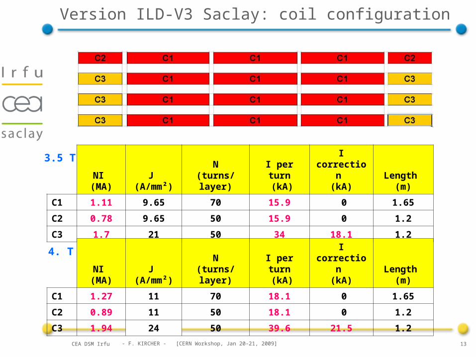
Version ILD-V3 Saclay: coil configuration
NI (MA)
J (A/mm²)
N(turns/layer)
I per turn (kA)
I correction (kA)
Length (m)
C1 1.11 9.65 70 15.9 0 1.65
C2 0.78 9.65 50 15.9 0 1.2
C3 1.7 21 50 34 18.1 1.2
NI (MA)
J (A/mm²)
N(turns/layer)
I per turn (kA)
I correction (kA)
Length (m)
C1 1.27 11 70 18.1 0 1.65
C2 0.89 11 50 18.1 0 1.2
C3 1.94 24 50 39.6 21.5 1.2
3.5 T
4. T

- F. KIRCHER - [CERN Workshop, Jan 20-21, 2009]CEA DSM Irfu 14
Version ILD-V3 Saclay: field homogeneity
(Br/Bz)dz vs r (z=0 to 2.25 m)
-6.00E+00
-4.00E+00
-2.00E+00
0.00E+00
2.00E+00
4.00E+00
6.00E+00
8.00E+00
0 0.5 1 1.5 2
r (m)
l (m
m)
ILD-V3 3.5 TeslaILD-V3 3.5 Tesla Gap filling 50%ILD-V3 3.5 Tesla Gap filling 100%ILD-V3 4 TeslaILD-V3 4 Tesla Gap filling 50%ILD-V3 4 Tesla Gap filling 100%
- F. KIRCHER - [CERN Workshop, Jan 20-21, 2009]CEA DSM Irfu 15
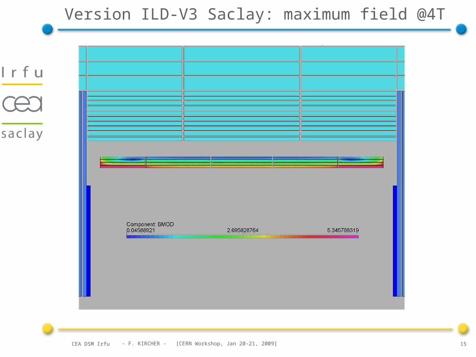
Version ILD-V3 Saclay: maximum field @4T

- F. KIRCHER - [CERN Workshop, Jan 20-21, 2009]CEA DSM Irfu 16
Version ILD-V3 Saclay: fringing field
ILD-V3 SACLAY @3.5 Tesla ILD-V3 SACLAY @4TeslaFringe Field(200 Gauss limit)
Requirements50 Gauss @15m @4T
100 Gauss @10m @4T
Filling%
B@ 4T
Z=10mB(Gauss)
B@ 3.5T
Z=10mB(Gauss)
0225150
50200120
100180100
Simulations
Filling%
B@ 4T
R=15mB(Gauss)
B@ 3.5T
R=15mB(Gauss)
0130100
5011075
1009055
Influence ofradial gap filling %
Gap filling 0% Gap filling 0%
Gap filling 50% Gap filling 50%
Gap filling 100% Gap filling 100%

- F. KIRCHER - [CERN Workshop, Jan 20-21, 2009]CEA DSM Irfu 17
Version ILD-V3 Saclay: comparison with CMS
• Parameter CMS ILD-V3 Saclay
Useful aperture (m) 6 6.9
Length (m) 12.5 7.35
Design field (T) 4 4
Max. field (T) 4.6 5.35
Nominal current (kA) 19.1 18.1
Extra correction current (kA)
0 21.5
Coil configuration 5 modules * 4 layers, same length
5 modules * 4 layers, 2 ≠ lengths
Stored energy (GJ) 2.6 2.05
Density of stored energy (kJ/kg)
11.6 12.4

- F. KIRCHER - [CERN Workshop, Jan 20-21, 2009]CEA DSM Irfu 18
Summary
IntroductionIntroduction
1.Version ILD-V3 Saclay for the magnet configurationVersion ILD-V3 Saclay for the magnet configuration
1.1 Parameter list1.1 Parameter list
1.2 Coil and yoke design1.2 Coil and yoke design
1.3 Main outputs1.3 Main outputs
1.4 Comparison CMS-ILD1.4 Comparison CMS-ILD
2.Some other points
2.1 Modules with correction current
2.2 Anti DiD coil design
ConclusionsConclusions

- F. KIRCHER - [CERN Workshop, Jan 20-21, 2009]CEA DSM Irfu 19
Modules with correction current
This is one of the main novelty from CMS.
Basic concepts:
-the conductor with the extra correction current has:
. the same overall dimension as the conductor with the main current, typically 80*22 mm2 without insulation (a little bit longer than the CMS conductor)
. but a higher current transport capacity to work with about the same safety margin with respect to the critical current (40 strands * Ø 1.7 mm vs 32 strands * Ø 1.3 mm)
-a stronger mechanical support: at least for the conductor with the extra correction current, the ratio of structural material is close to 1 (cf conductor for the ATLAS Central Solenoid developed by Akira Yamamoto et al.), vs 0.6 for CMS
-in case of quench, the extra local Joule heating is absorbed by the quench-back phenomenon, much quicker than the increase of temperature of the coil, and which diffuses the uniformly the heat

- F. KIRCHER - [CERN Workshop, Jan 20-21, 2009]CEA DSM Irfu 20
Anti-DID coil design
. Two dipole coils, anti-symetric with respect to the I.P.
. Proposal to wind the anti-DID coil outside the main solenoid coil (reduced field region)
. Field maps (3D) do not yet include the ILD solenoid
. Banti-DID ~ 0.065 T
The anti-DiD allows to zero the crossing angle for the outgoing beam (and pairs) behind the I.P.
Brett Parker has started some conceptual design study

- F. KIRCHER - [CERN Workshop, Jan 20-21, 2009]CEA DSM Irfu 21
Summary
IntroductionIntroduction
1.Version ILD-V3 Saclay for the magnet configurationVersion ILD-V3 Saclay for the magnet configuration
1.1 Parameter list1.1 Parameter list
1.2 Coil and yoke design1.2 Coil and yoke design
1.3 Main outputs1.3 Main outputs
1.4 Comparison CMS-ILD1.4 Comparison CMS-ILD
2.Some other pointsSome other points
2.1 Modules with correction current1 Modules with correction current
2.2 Anti DiD coil design2.2 Anti DiD coil design
Conclusions

- F. KIRCHER - [CERN Workshop, Jan 20-21, 2009]CEA DSM Irfu 22
Conclusions
•Magnetic calculations have been done with the LoI parameters. Solutions which meet the specifications have been found
•Most of the CMS concepts can still be used. Some R&D on a conductor with a ratio of structural material close to 1 would strenghten the mechanical design of the most solicited modules
•Conceptual design of the anti-DID has started, and must continue with the present detector magnet configuration
•Even if some points can still evolved and/or need some more studies , the present design seems at an acceptable level of study for the LoI