
IJRSP 40(5) 275-281
7
Indian Journal of Radio & Space Physics Vol 40, October 2011, pp 275-281 Design of broadband circular patch microstrip antenna with diamond shape slot Garima 1 , D Bhatnagar 1,$,* , J S Saini 1 , V K Saxena 1 & L M Joshi 2 1 Microwave Laboratory, Department of Physics, University of Rajasthan, Jaipur 302 004 2 Central Electronics Engineering Research Institute (CEERI), Pilani 333 031 $ E-mail: d [email protected] Received 3 September 2010; revis ed receive d and acce pted 8 July 2011 The radiation performance of a circular patch microstrip antenna having a concentric diamond shape slot has been presented in this paper. The side lengths and angles of the inserted diamond shape slot have been optimized to achieve a single layer multi frequency microstrip antenna applicable for C band space communication systems. For simulation work, IE3D simulation software has been applied and later this antenna has been designed and tested by applying glass epoxy FR-4 substrate. The proposed antenna provides much improved bandwidth (measured impedance bandwidth 0.87 GHz or 13.58%) than a conventional circular patch antenna. The gain of proposed antenna is almost constant in the frequency range where broadband performance is realized, however, it is improved considerably in comparison to a conventional circular patch antenna. The performance of proposed antenna has been compared with that of a conventional circular patch antenna having identical patch radius. The measured co and cross polar patterns of proposed antenna at one of the three resonance frequencies have been presented. Keywords: Circular patch microstrip antenna, Microstrip antenna, Broadband antenna PACS No.: 84.40.Ba 1 Introduction In recent times, microstrip antennas have attracted the attention of scientists for their possible applications in satellite, mobile and wireless communication systems due to their compact size, light weight and easy production characteristics. These antennas, in general, resonate efficiently at a single resonance frequency corresponding to their dominant mode and have typically narrow bandwidth (1-2%) and low gain 1,2 . Therefore, in their conventional form, microstrip antennas fail to find much application in modern satellite and wireless communication systems. Satellite mounted antennas operating in C band of frequency spectrum must be conformal and compact in size, capable of operating at two or more frequencies at a time and must present broadband performance. Considering these requirements, conventional printed circuit antennas fail to serve their purpose in satellite communication systems. Extensive work in recent past has been reported through modifications in conventional microstrip antenna geometries. Lee et al. 3 reported a round corner rectangular wide slot antenna with novel feeding geometry to have better wideband characteristics than a normal rectangular wide slot antenna. Printed wide-slot antenna fed by a microstrip line with a fork-like tuning stub was proposed to achieve improved impedance and gain bandwidths 4 . Wong & Hsu 5 applied a U-shaped slot in an equilateral triangular microstrip antenna to make it broadband structure while improved bandwidth up to 8.67% was recently reported for a circular patch antenna having U-slot 6 . A semi- circular slot antenna with a protruded small rectangular slot was excited by a 50 ohm microstrip line 7 to achieve broadband performance. Krishna et al. 8 reported the improved bandwidth design of a compact dual band slot loaded circular microstrip antenna with a superstrate. Bao & Ammann 9 proposed the design of a compact circularly polarized wideband circular patch antenna embedded in a narrow annular-ring which uses an unequal cross-slotted ground plane. Azenui & Yang 10 proposed a transmission line fed crescent patch antenna with displaced center of circular region from center of outer ellipse for wide band applications. Bhardwaj et al. 11 applied a pair of triangular notches in square patch geometry while Sharma et al. 12 applied a narrow L–shaped slot in right triangular patch geometry to achieve broadband performance.
-
Upload
ngoc-lan-nguyen -
Category
Documents
-
view
221 -
download
0
Transcript of IJRSP 40(5) 275-281

7/27/2019 IJRSP 40(5) 275-281
http://slidepdf.com/reader/full/ijrsp-405-275-281 1/7
Indian Journal of Radio & Space PhysicsVol 40, October 2011, pp 275-281
Design of broadband circular patch microstrip antenna with diamond shape slot
Garima1, D Bhatnagar1,$,*, J S Saini1, V K Saxena1 & L M Joshi2 1Microwave Laboratory, Department of Physics, University of Rajasthan, Jaipur 302 004
2Central Electronics Engineering Research Institute (CEERI), Pilani 333 031$E-mail: [email protected]
Received 3 September 2010; revised received and accepted 8 July 2011
The radiation performance of a circular patch microstrip antenna having a concentric diamond shape slot has beenpresented in this paper. The side lengths and angles of the inserted diamond shape slot have been optimized to achieve asingle layer multi frequency microstrip antenna applicable for C band space communication systems. For simulation work,IE3D simulation software has been applied and later this antenna has been designed and tested by applying glass epoxyFR-4 substrate. The proposed antenna provides much improved bandwidth (measured impedance bandwidth 0.87 GHz or13.58%) than a conventional circular patch antenna. The gain of proposed antenna is almost constant in the frequency rangewhere broadband performance is realized, however, it is improved considerably in comparison to a conventional circularpatch antenna. The performance of proposed antenna has been compared with that of a conventional circular patch antennahaving identical patch radius. The measured co and cross polar patterns of proposed antenna at one of the three resonancefrequencies have been presented.
Keywords: Circular patch microstrip antenna, Microstrip antenna, Broadband antenna
PACS No.: 84.40.Ba
1 IntroductionIn recent times, microstrip antennas have attracted
the attention of scientists for their possibleapplications in satellite, mobile and wirelesscommunication systems due to their compact size,light weight and easy production characteristics.These antennas, in general, resonate efficientlyat a single resonance frequency corresponding totheir dominant mode and have typically narrowbandwidth (1-2%) and low gain1,2. Therefore, in theirconventional form, microstrip antennas fail to findmuch application in modern satellite and wirelesscommunication systems. Satellite mounted antennasoperating in C band of frequency spectrum must be
conformal and compact in size, capable of operatingat two or more frequencies at a time and mustpresent broadband performance. Considering theserequirements, conventional printed circuit antennasfail to serve their purpose in satellite communicationsystems. Extensive work in recent past has beenreported through modifications in conventionalmicrostrip antenna geometries. Lee et al.
3 reported around corner rectangular wide slot antenna withnovel feeding geometry to have better widebandcharacteristics than a normal rectangular wide slot
antenna. Printed wide-slot antenna fed by amicrostrip line with a fork-like tuning stub was
proposed to achieve improved impedance and gainbandwidths4. Wong & Hsu5 applied a U-shapedslot in an equilateral triangular microstrip antenna tomake it broadband structure while improvedbandwidth up to 8.67% was recently reported fora circular patch antenna having U-slot6. A semi-circular slot antenna with a protruded smallrectangular slot was excited by a 50 ohm microstripline7 to achieve broadband performance. Krishnaet al.
8 reported the improved bandwidth design of a compact dual band slot loaded circular microstripantenna with a superstrate. Bao & Ammann9
proposed the design of a compact circularlypolarized wideband circular patch antenna embeddedin a narrow annular-ring which uses an unequalcross-slotted ground plane. Azenui & Yang10 proposed a transmission line fed crescent patchantenna with displaced center of circular region fromcenter of outer ellipse for wide band applications.Bhardwaj et al.
11 applied a pair of triangular notchesin square patch geometry while Sharma et al.
12 applied a narrow L–shaped slot in right triangularpatch geometry to achieve broadband performance.

7/27/2019 IJRSP 40(5) 275-281
http://slidepdf.com/reader/full/ijrsp-405-275-281 2/7
INDIAN J RADIO & SPACE PHYS, OCTOBER 2011276
In this paper, a novel design of single layeredcircular microstrip antenna having concentricdiamond shaped slot is proposed and its simulated
and measured radiation performances in free spaceconditions have been presented. The proposedantenna is found useful for satellite communicationsystems as it presents the desired performances, viz. improved bandwidth and gain and multiple operatingfrequencies needed for satellite communicationsystems. A comparison of performance of proposeddesign with conventional circular patch antennahaving identical patch radius has also been reportedfor better understanding.
2 Circular microstrip patch antennaFirst, a circular patch microstrip antenna with
radius, r, has been considered. The patch having
substrate thickness (h << λ o), substrate dielectric
constant ε r and relative permeability µ r = 1 has beenconsidered lying in XY plane over a large groundplane as shown in Fig. 1. The magnetic field in thisstructure has essentially x and y components. Since
h << λo, the fields do not vary along the z-directionand the component of the current; normal to theedge of the microstrip antenna approaches to zeroat the edges. With these assumptions, structure hasbeen considered as a cylindrical resonator with
magnetic sidewalls, bounded at its top and bottomby electric walls.
Following the formulations proposed by Carver13,it is found that an inset feed circular patchantenna having patch radius of 16.2 mm; resonates attwo frequencies 5.906 and 7.49 GHz in the C-bandwhen it is designed on glass epoxy FR-4 substrate(εr = 4.4, tanδ = 0.025, substrate thickness, h = 0.159 cm)with infinite ground plane. These two frequenciescorrespond to TM31 and TM12 modes of excitation.
The simulated reflection coefficient (S11) variation of same antenna with frequency obtained by usingIE3D software14 has been shown in Fig. 2. This
variation indicates that resonance frequencies of antenna in C-band are 5.819 and 7.419 GHz,respectively which are very close to computedresonance frequencies. The impedance bandwidthscorresponding to both resonance frequencies arevery low (2.42 and 2.53%, respectively). Thegain and efficiencies of antenna are also verypoor. These outcomes suggest that circular patchantenna in its present form is not suitable forapplication in satellite communication systems.Therefore, this patch geometry has been modifiedby introducing concentric diamond shaped slot atthe center of the patch geometry and its performancehas been presented.
3 Circular patch antenna with diamond shaped
slotThe single layered circular patch geometry
discussed above has been modified by inserting aconcentric diamond shape slot in the circular patchgeometry as shown in Fig. 3(a). The top viewof designed antenna has been shown in Fig. 3(b).The circular patch with infinite ground plane designedon glass epoxy FR-4 substrate still has radius of 16.2 mm. On applying a diamond shaped slot of dimensions ‘a’ and ‘b’ on patch geometry as shownin Fig. 3(a), in addition to already existing TM31 andTM12 modes in conventional circular patch antenna,few additional modes get excited. This fact maybe visualized through the presence of additional dipsin Fig. 4.
Fig. 1—Geometry of conventional circular patch antennaFig. 2—Simulated variation of return loss as a function of frequency

7/27/2019 IJRSP 40(5) 275-281
http://slidepdf.com/reader/full/ijrsp-405-275-281 3/7
GARIMA et al.: BROADBAND CIRCULAR PATCH ANTENNA - DESIGN 277
Fig. 3a—View of circular patch geometry with concentricdiamond slot
Fig. 4—Variation of return loss with change in slot dimensions
It may be realized that on increasing the size of inserted slot, the effective radius of circular patchdecreases, which in turn increases the resonancefrequency of antenna under consideration. Extensiveoptimization in side lengths and slot angles has beencarried out and three representative variations of S11 parameters as a function of frequency have beenshown in Fig. 4. From these variations, it has been
realized that on selecting a = 4 mm and b = 8 mm,input bandwidth of antenna approaches to 17.28%while on selecting a = 7 mm and b = 11 mm, inputbandwidth approaches to 20.78%. With insertion of diamond shaped slot in the patch geometry, the pathof patch current increases, which in turn improves theimpedance bandwidth of antenna. In addition tothis fact, an additional mode TMmn mode close toTM12 mode also gets excited and the two resonancefrequencies corresponding to TM12 and TM31 modesmove towards higher frequency side. On increasing
Fig. 3b—View of designed circular patch geometry withconcentric diamond slot
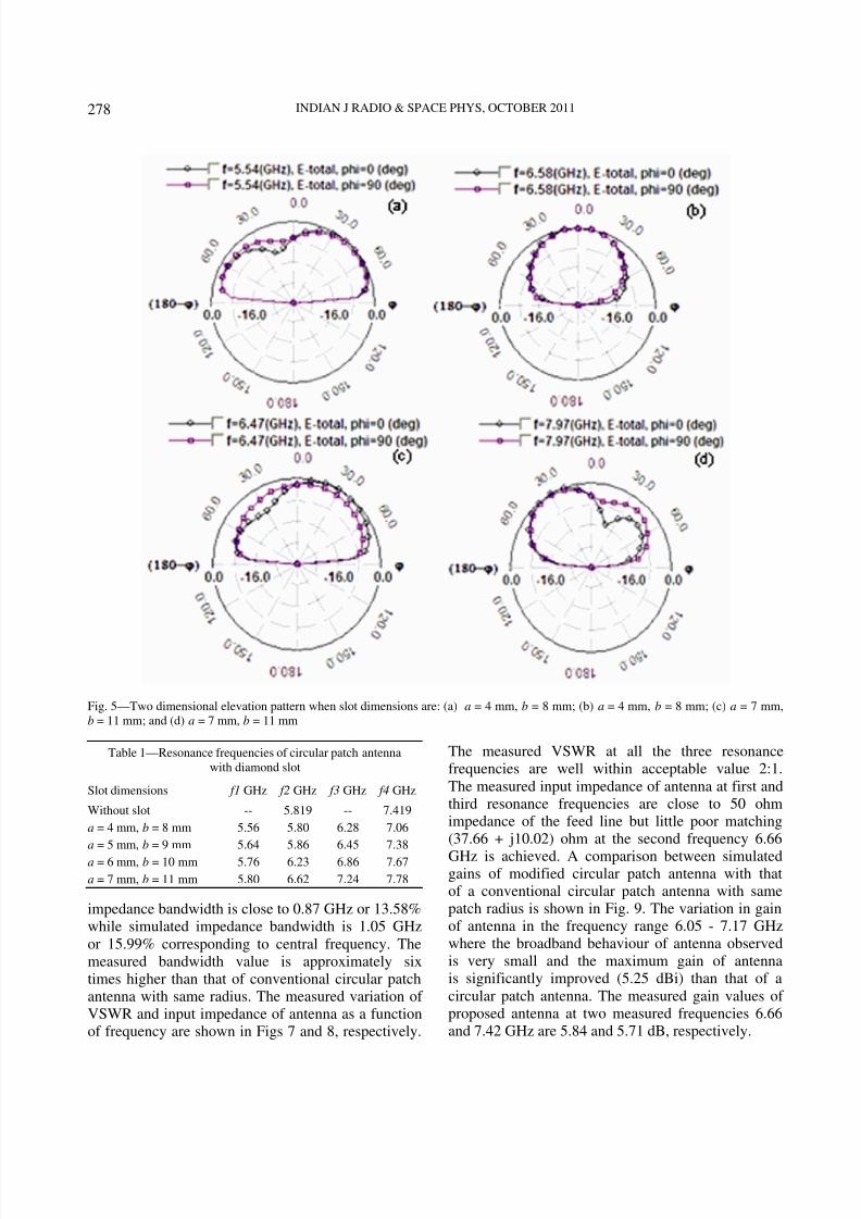
the parameters a and b, a stage arrives wherethe return loss curves corresponding to additionalTMmn mode and TM12 modes start overlapping eachother to give improved bandwidth. This bandwidthvalue keeps on increasing with increase in slot size.Finally, a limit of parameters a and b arrives andthereafter, bandwidth of antenna starts decreasing.However, in two cases mentioned above, viz. a = 4 mm,b = 8 mm and a = 7 mm, b = 11 mm, the radiationpatterns in the entire frequency bandwidth are notidentical in shape as shown in Fig. 5 for two
representative frequencies. An improvement inimpedance bandwidth of antenna is not useful tillidentical radiation patterns in entire bandwidth rangeare not achieved.
It is realized that out of four geometries reported inTable 1, overall best performance may be achievedwith a circular patch antenna having diamond slothaving dimensions a = 6 mm and b = 10 mm andtherefore, entire work is reported on this antenna.Structure is fed through an inset feed arrangementusing a SMA connector associated with 50 ohmfeed line. The simulation results suggest that in the
range of 5.85 - 7.5 GHz, antenna resonates at twofrequencies 6.23 and 6.859 GHz as shown inFig. 6(a). These frequencies are significantly close tomeasured resonance frequencies 6.166 and 6.66 GHz.An additional resonance frequency 7.42 GHz of antenna is also realized as shown in Fig. 6(b), whichin simulation results is realized beyond 7.5 GHz.With insertion of diamond shaped slot in the patchgeometry, the measured S11 curves correspondingto frequencies 6.166 and 6.66 GHz overlap eachother to provide improved bandwidth. The measured
7/27/2019 IJRSP 40(5) 275-281
http://slidepdf.com/reader/full/ijrsp-405-275-281 4/7
INDIAN J RADIO & SPACE PHYS, OCTOBER 2011278
Fig. 5—Two dimensional elevation pattern when slot dimensions are: (a) a = 4 mm, b = 8 mm; (b) a = 4 mm, b = 8 mm; (c) a = 7 mm,b = 11 mm; and (d) a = 7 mm, b = 11 mm
Table 1—Resonance frequencies of circular patch antennawith diamond slot
Slot dimensions f1 GHz f2 GHz f3 GHz f4 GHz
Without slot -- 5.819 -- 7.419
a = 4 mm, b = 8 mm 5.56 5.80 6.28 7.06
a = 5 mm, b = 9 mm 5.64 5.86 6.45 7.38
a = 6 mm, b = 10 mm 5.76 6.23 6.86 7.67
a = 7 mm, b = 11 mm 5.80 6.62 7.24 7.78
impedance bandwidth is close to 0.87 GHz or 13.58%while simulated impedance bandwidth is 1.05 GHzor 15.99% corresponding to central frequency. Themeasured bandwidth value is approximately sixtimes higher than that of conventional circular patchantenna with same radius. The measured variation of VSWR and input impedance of antenna as a functionof frequency are shown in Figs 7 and 8, respectively.
The measured VSWR at all the three resonancefrequencies are well within acceptable value 2:1.The measured input impedance of antenna at first andthird resonance frequencies are close to 50 ohmimpedance of the feed line but little poor matching(37.66 + j10.02) ohm at the second frequency 6.66
GHz is achieved. A comparison between simulatedgains of modified circular patch antenna with thatof a conventional circular patch antenna with samepatch radius is shown in Fig. 9. The variation in gainof antenna in the frequency range 6.05 - 7.17 GHzwhere the broadband behaviour of antenna observedis very small and the maximum gain of antennais significantly improved (5.25 dBi) than that of acircular patch antenna. The measured gain values of proposed antenna at two measured frequencies 6.66and 7.42 GHz are 5.84 and 5.71 dB, respectively.

7/27/2019 IJRSP 40(5) 275-281
http://slidepdf.com/reader/full/ijrsp-405-275-281 5/7
GARIMA et al.: BROADBAND CIRCULAR PATCH ANTENNA - DESIGN 279
Fig. 7—Measured VSWR of modified circular patch antenna
Fig. 8—Measured input impedance of modified circular patchantenna as a function of frequency
Fig. 9—Comparison of simulated gain of modified circular patchantenna with conventional circular patch antenna
Fig. 10—Simulated E and H plane elevation patterns of antenna atdifferent frequencies
Fig. 6—(a) Simulated; and (a) Measured return loss of modified circular patch antenna

7/27/2019 IJRSP 40(5) 275-281
http://slidepdf.com/reader/full/ijrsp-405-275-281 6/7
INDIAN J RADIO & SPACE PHYS, OCTOBER 2011280
Fig. 11—Co and cross polar patterns of antenna: (a) Simulated E-plane at 6.86 GHz frequency; (b) Measured E-plane at 6.66 GHzfrequency; (c) Simulated H-plane at 6.86 GHz frequency; and (d) Measured H-plane at 6.66 GHz frequency
The simulated two dimensional E and H planeelevation patterns of modified circular microstrippatch antenna at two frequencies covering 6.05 - 7.11GHz frequency range where broadband performanceis realized are shown in Fig. 10. Within the selectedfrequency range, the radiation patterns of antennaare more or less identical in shape and the directionof maximum radiation is nearly normal to the patchgeometry. The simulated and measured co and crosspolar patterns of this antenna in E and H planesat frequency 6.66 GHz are shown in Figs 11(a-d).These patterns suggest that the simulated andmeasured patterns are almost identical in shape. InE-plane, the co-polar patterns are nearly 10 dB higherthan cross polar patterns; while in H-plane, theco-polar patterns are nearly 8 dB higher than crosspolar patterns.
4 Discussion and ConclusionsThe radiation performance of a single layer
concentric circular patch antenna having a diamondshape slot is reported in this paper through simulation
analysis and measured results. The simulationanalysis is carried out by applying IE3D simulationsoftware. The proposed antenna is designed onlow-cost and easily available FR4 substrate. Thedesigned antenna offers improved impedancebandwidth required for C-band for spacecommunication systems. In the impedance bandwidthrange, the gain of antenna is improved significantlythan that of a conventional circular patch antenna.The elevation radiation patterns within the frequency
range of interest are almost identical in shape.The reported results indicate that the proposedantenna geometry fulfills all the requirements foran antenna required for satellite communicationsystems, hence, may be proved useful structure forsatellite communication systems.
AcknowledgementsThe authors express their sincere thanks to
Department of Sscience and Technology, New Delhifor supporting the research work. The authors are also

7/27/2019 IJRSP 40(5) 275-281
http://slidepdf.com/reader/full/ijrsp-405-275-281 7/7
GARIMA et al.: BROADBAND CIRCULAR PATCH ANTENNA - DESIGN 281
thankful to Dr Rajeev Jyoti and Mr Alok Singhal,ISRO Satellite Center, Ahmedabad for their help.
References1 Wong K L, Compact and broadband microstrip antennas (John Wiley, New York), 2003.
2 Kumar G & Ray K P, Broadband microstrip antennas (Artech House, London), 2003.
3 Lee H L, Lee H J, Yook J G & Park H K, Broadbandplanar antenna having round corner rectangular wide slot,IEEE Antennas Propag Int Symp Digest (USA), 2 (2002)460.
4 Sze J Y & Wong K L, Bandwidth enhancement of amicrostrip-line-fed printed wide-slot antenna, IEEE Trans
Antennas Propag (USA), 49 (2001) 1020.5 Wong K L & Hsu W S, Broadband triangular microstrip
antenna with U-shaped slot, Electron Lett (UK), 33 (1997)2085.
6 Sharma V, Saxena V K, Bhatnagar D, Saini J S &Sharma K B, Compact dual frequency wide bandcircular patch antenna with U-slot, Proc of IEEE
International Symposium on Antenna and Propagation
and USNC/URSI National Radio Science Meeting,(IEEE, USA), 1979, 1.
7 Chen W S, Hung C C & Wong K L, A novel microstrip-line-fed printed semicircular slot antenna for broadbandoperation, Microw Opt Technol Lett (USA), 26 (2000) 237.
8 Krishna D D, Gopikrishna M, Aanandan C K, Mohanan P &
Vasudevan K, Design of a compact dual band slot loadedcircular microstrip antenna with a superstrate, Prog
Electromagn Res (Hong Kong), 83 (2008) 245.9 Bao X L & Ammann M J, Compact annular-ring embedded
circular patch antenna with cross-slot ground plane forcircular polarization, Electron Lett (UK), 42 (2006) 192.
10 Azenui N C & Yang H Y D, A printed crescent patchantenna for ultra wideband applications, IEEE Antennas
Wireless Propag Lett (USA), 6 (2007) 113.11 Bhardwaj D, Bhatnagar D, Sancheti S & Soni B, Radiations
from double notched square patch antenna on FR4 substrate, J
Microw, Optoelectron Electromagn Appl (Brazil), 7 (2008) 54.12 Sharma V, Shekhawat S, Saxena V K, Saini J S, Sharma K
B, Soni B & Bhatnagar D, Right isosceles triangularmicrostrip antenna with narrow L-shaped slot, Microw Opt
Technol Lett (USA), 51 (2009) 3006.13 Carver K R, Practical analytical techniques for the microstrip
antenna, Proc Workshop Printed Circuit Antenna Technology (New Mexico State Univ, Las Cruces, USA), 1979, 1.
14 IE3D Software, Release 8 (Zeland Software Inc. Freemont,USA), 2010.