IJISET - International Journal of Innovative Science ...ijiset.com/v1s5/IJISET_V1_I5_10.pdf ·...
13
IJISET - International Journal of Innovative Science, Engineering & Technology, Vol. 1 Issue 5, July 2014. www.ijiset.com ISSN 2348 – 7968 “Fault Diagnosis of Power Distribution System using Interval Type-2 Fuzzy Data mining” 1 Neelam Sahu, 2 Manoj Jha, 3 M. F. Qureshi 1 Ph.D. Scholar, Computer Science Department, Dr. C.V. Raman University, Bilaspur, India ([email protected]) 2 Department of Applied Mathematics, Rungta Engg. College, Raipur, India ([email protected]) 3 Department of Electrical Engg., Govt. Polytechnic Dhamtari, India ([email protected]) Abstract In this paper a noble method of fault locating in a radial power distribution system is discussed. Interval type-2 fuzzy system will ease the calculation involved. The history associated with fault occurred in power system can be effectively used as a strong database. This database will act as the trainer to the interval type-2 fuzzy expert system. A rich history of faulty area will enhance the performance of the interval type-2 Fuzzy Fault Identification System (IT2FFIS). Fault section location aims to identify the faulty area in the power system using the post fault status of protective relays and circuit breakers and diagnose the cause of a fault that has occurred. Restoration cost can be significantly reduced by accurately identifying a fault location and its cause, which also reduces the restoration time of the faulty section. In this paper methodology based on interval type-2 fuzzy expert system is discussed for assistance to the operators for easy fault detection. The utility of the soft computing methodology is highlighted. Generally interval type-2 fuzzy sets are suitable for handling the issues related to understandability of patterns, incomplete/noisy data, mixed media information and human interaction, and can provide approximate solutions faster. Neural networks are nonparametric, robust, and exhibit good learning and generalization capabilities in data-rich environments. Genetic algorithms provide efficient search algorithms to select a model, from mixed media data, based on some preference criterion/objective function. Rough sets are suitable for handling different types of uncertainty in data. The interval type-2 fuzzy sets are used here for data mining for fault location in the distribution system. Keywords: Interval Type-2 Fuzzy Expert System (IT2FES), Power Distribution System, Knowledge Discovery in Database (KDD), Supervisory Control and data acquisition systems (SCADA), Data Mining (DM). I. Introduction Data mining is a form of knowledge discovery essential for solving problems in a specific domain. New knowledge may be obtained in the process while eliminating one of the largest costs, viz., data collection. Power system failure data, for example, often exists in vast quantities in an unstructured format. The application of data mining can facilitate systematic analysis in such cases. Soft computing is a consortium of methodologies that works synergistically and provides, in one form or another, flexible information processing capability for handling real-life ambiguous situations. Its aim is to exploit the tolerance for imprecision, uncertainty, approximate reasoning, and partial truth in order to achieve tractability, robustness, and low-cost solutions. Soft computing methodologies (involving fuzzy sets, neural networks, genetic algorithms, and rough sets) are most widely applied in the data mining step of the overall KDD process. The term KDD refers to the overall process of knowledge discovery in databases. Fuzzy sets (type-1 & type-2) provide a natural framework for the 71
Transcript of IJISET - International Journal of Innovative Science ...ijiset.com/v1s5/IJISET_V1_I5_10.pdf ·...

IJISET - International Journal of Innovative Science, Engineering & Technology, Vol. 1 Issue 5, July 2014. www.ijiset.com
ISSN 2348 – 7968
“Fault Diagnosis of Power Distribution System using Interval Type-2 Fuzzy Data mining”
1 Neelam Sahu, 2Manoj Jha, 3 M. F. Qureshi
1Ph.D. Scholar, Computer Science Department, Dr. C.V. Raman University, Bilaspur, India
([email protected]) 2Department of Applied Mathematics, Rungta Engg. College, Raipur, India
([email protected]) 3Department of Electrical Engg., Govt. Polytechnic Dhamtari, India
([email protected]) Abstract
In this paper a noble method of fault locating in a radial power distribution system is discussed. Interval type-2
fuzzy system will ease the calculation involved. The history associated with fault occurred in power system can be effectively
used as a strong database. This database will act as the trainer to the interval type-2 fuzzy expert system. A rich history of
faulty area will enhance the performance of the interval type-2 Fuzzy Fault Identification System (IT2FFIS). Fault section
location aims to identify the faulty area in the power system using the post fault status of protective relays and circuit
breakers and diagnose the cause of a fault that has occurred. Restoration cost can be significantly reduced by accurately
identifying a fault location and its cause, which also reduces the restoration time of the faulty section. In this paper
methodology based on interval type-2 fuzzy expert system is discussed for assistance to the operators for easy fault detection.
The utility of the soft computing methodology is highlighted. Generally interval type-2 fuzzy sets are suitable for handling
the issues related to understandability of patterns, incomplete/noisy data, mixed media information and human interaction,
and can provide approximate solutions faster. Neural networks are nonparametric, robust, and exhibit good learning and
generalization capabilities in data-rich environments. Genetic algorithms provide efficient search algorithms to select a
model, from mixed media data, based on some preference criterion/objective function. Rough sets are suitable for handling
different types of uncertainty in data. The interval type-2 fuzzy sets are used here for data mining for fault location in the
distribution system.
Keywords: Interval Type-2 Fuzzy Expert System (IT2FES), Power Distribution System, Knowledge Discovery in Database
(KDD), Supervisory Control and data acquisition systems (SCADA), Data Mining (DM).
I. Introduction Data mining is a form of knowledge discovery essential for solving problems in a specific domain. New
knowledge may be obtained in the process while eliminating one of the largest costs, viz., data collection. Power system
failure data, for example, often exists in vast quantities in an unstructured format. The application of data mining can
facilitate systematic analysis in such cases. Soft computing is a consortium of methodologies that works synergistically and
provides, in one form or another, flexible information processing capability for handling real-life ambiguous situations. Its
aim is to exploit the tolerance for imprecision, uncertainty, approximate reasoning, and partial truth in order to achieve
tractability, robustness, and low-cost solutions. Soft computing methodologies (involving fuzzy sets, neural networks, genetic
algorithms, and rough sets) are most widely applied in the data mining step of the overall KDD process. The term KDD refers
to the overall process of knowledge discovery in databases. Fuzzy sets (type-1 & type-2) provide a natural framework for the
71

IJISET - International Journal of Innovative Science, Engineering & Technology, Vol. 1 Issue 5, July 2014. www.ijiset.com
ISSN 2348 – 7968
process in dealing with uncertainty. Neural networks and rough sets are widely used for classification and rule generation.
Genetic algorithms (GAs) are involved in various optimization and search processes, like query optimization and template
selection. KDD refers to the overall process of turning low-level data into high-level knowledge. An important step in the
KDD process is data mining. Data mining is an interdisciplinary field with a general goal of predicting outcomes and
uncovering relationships in data.
II. System Description
The complexity of today’s power system has grown enormously and to have efficient operation of power
transmission and distribution network Supervisory Control and data acquisition systems (SCADA) are in use. SCADA is
being though widely used in power system but its accuracy has always been a question mark. In Fig.1, zone-1 trips for faults
from breaker CB1 to 80 percent of the line length toward breaker CB2. Zone two operates for faults beyond bus Y including
some percentage of the transmission line between breakers CB4 and CB3 and the transformer supplying the load at bus Y.
Zone three looks backward toward the source and covers the step-up transformer, plus a percentage of the transmission line
between breaker CB3 and CB4. Consider a fault on the transmission line between breakers CB3 and CB4.
Assume that breaker CB3 operates correctly but breaker CB4 does not. When a breaker fails to operate, the
fault is then removed by back- up breakers. In such cases, the outage range is very large and it is difficult for the dispatchers
to judge where the fault is located. Moreover the relay time settings in power system are much smaller and consequently it
gets difficult to set the time delays with enough accuracy.
In case of such failures serious implications may arise which may affect both i.e. customer and the power
system. Occasional cases may arise where multiple faults may occur, with many breakers being tripped within a short period.
Under such situation many alarm messages will be generated and will be received by the dispatch centre which becomes
impossible for the dispatchers to analyze the condition with satisfaction and accuracy. The problem can be overcome through
the trained system discussed which will employ the interval type-2 fuzzy logic calculations for fault section identification.
Fig.1 Three step Zone
III. Interval Type-2 Fuzzy Logic System In this paper a system is discussed for assistance to the operators in fault condition by the help of interval type-
2 fuzzy system. This is done by using the post fault status of the circuit breakers and relays. It then calculates membership
function for each possible fault section. The objective of this calculation is to determine the likelihood of each candidate fault
section as the actual fault section. Moreover membership function provides a convenient means of ranking among possible
(or candidate) fault sections, and are the most important factors in decision making. During decision making, the most
possible fault section is determined by maximum selection method. In this method most possible fault section is the one
which is having highest membership grade. MATLAB code for the proposed scheme is developed and the results obtained in
two cases for a power- system network.
Definition of a type-2 fuzzy set and its associated terminology
72

IJISET - International Journal of Innovative Science, Engineering & Technology, Vol. 1 Issue 5, July 2014. www.ijiset.com
ISSN 2348 – 7968
Type-1 fuzzy logic controllers employ crisp and precise Type-1 fuzzy sets. For example, consider a Type-1
fuzzy set representing the linguistic label of ‘Low’ voltage in Fig.2(a). If the input voltage x is 115v, then the membership of
this input to the ‘Low’ set will be the certain and crisp membership value of 0.4. However, the center and end points of this
Type-1 fuzzy set can vary due to uncertainties (which could arise for example from noise) in the measurement of voltage
(numerical uncertainty) and in the situations in which 115v could be called low (linguistic uncertainty). If this linguistic label
was employed with a fuzzy logic controller, then the Type-1 fuzzy logic controller would need to be frequently tuned to
handle such uncertainties. Alternatively, one would need to have a group of separate Type-1 sets and Type-1 fuzzy logic
controllers, where each fuzzy logic controller will handle a certain situation. On the other hand, a Type-2 fuzzy set is
characterized by a fuzzy MF, i.e. the membership value (or membership grade) for each element of this set is itself a fuzzy set
in [0,1]. For example if the linguistic label of ‘Low’ voltage is represented by a Type-2 fuzzy set as shown in Fig. 2b, then the
input x of 115v will no longer have a single value for the MF. Instead, the MF takes on values wherever the vertical line
intersects the area shaded in gray. Hence, 115v will have primary membership values that lie in the interval [0.15, 0.65].
(a) (b) (c)
Fig.2 a) A type-1 fuzzy set. b) A type-2 fuzzy set- primary membership function. c) An interval type-2 fuzzy set secondary
MF (drawn with dotted lines) and a general type-2 MF (solid line) at a specific point x′.
Each point of this interval will have also a weight associated with it. Consequently, this will create an
amplitude distribution in the third dimension to form what is called a secondary membership function, which can be a triangle
as shown in Fig.2c. If the secondary membership function is equal to 1 for all the points in the primary membership and if
this is true for ∀x∈ X, we have the case of an Interval Type-2 fuzzy set (IT2FS). The input x of 115v will now have a primary
membership and an associated secondary MF. The MFs of type-2 fuzzy sets are three dimensional and include a Footprint of
Uncertainty (FOU) (shaded in gray in Fig.2b). It is the new third-dimension of Type-2 fuzzy sets and the FOU that provide
additional degrees of freedom and that make it possible to directly model and handle the numerical uncertainties (for
example, uncertainty in video packet delay measurements) and linguistic uncertainties (for example, uncertainty, in modeling
cross-traffic characteristics). A Type-2 fuzzy set �̃� is characterized by a T2 MF μA˜(x, u) where x ∈ X and u ∈ Jx ⊆ [0, 1], i.e.,
�̃� = ��(𝑥,𝑢), 𝜇𝐴�(𝑥,𝑢)�,∀ 𝑥 ∈ 𝑋,∀𝑢 ∈ 𝐽𝑥 ⊆ [0,1]�
in which 0 ≤ μA˜(x, u) ≤ 1. �̃� can also be expressed as follows
�̃� = ∫𝑥∈𝑋∫𝑢∈𝐽𝑥𝜇𝐴�(𝑥,𝑢)/(𝑥,𝑢), 𝐽𝑥 ⊆ [0,1]
Where ∫∫ denotes union over all admissible x and u. For where ∫∫ denotes union over all admissible x and u. For
discrete universes of discourse ∫ is replaced by P. A suitable way to describe a T2 MF is in relationship to its secondary MFs.
For example, when fx(u)=1, ∀u ∈ Jx ⊆ [0,1], then the secondary MFs are interval sets, and if this is true for ∀ x∈ X, we have
the case of an interval type-2 membership function, which characterizes the Interval Type-2 fuzzy sets (IT2FS) that will be
used in this paper. Interval secondary MFs reflect a uniform uncertainty at the primary memberships of x. Since all the
memberships in an interval set are unity, an interval set is represented just by its domain interval which can be represented by
its left and right end-points as [l, r]. The two end-points are associated with two Type1 MFs that are referred to as Upper MF
73

IJISET - International Journal of Innovative Science, Engineering & Technology, Vol. 1 Issue 5, July 2014. www.ijiset.com
ISSN 2348 – 7968
(UMF) and Lower MF (LMF). The UMF and LMF are bounds for the FOU (�̃�) of an IT2 fuzzy set �̃�. The UMF is associated
with the upper bound of FOU (�̃�) and is denoted by �̅�𝐴�(𝑥), ∀ x ∈ X. The LMF is associated with the lower bound of
FOU��̃�� and is denoted by 𝜇�(𝐴), ∀x ∈ X. The interval type-2 fuzzy set �̃� can be represented in terms of upper and lower
membership functions as follows:
�̃� = ∫𝑥∈𝑋 �∫𝑢∈�𝜇𝐴�(𝑥),𝐴�𝐴�(𝑥)�1 𝜇� � /𝑥
This paper’s input and output variables will be represented by IT2 fuzzy sets as they are simpler to work and
they distribute the uncertainty evenly among all admissible primary memberships. General T2 fuzzy logic control is
computationally intensive, whereas the computation simplifies considerably with an IT2 controller using IT2 fuzzy sets. This
will enable us to design a T2 FLC that operates in real-time. For discrete universes of discourse X and U, Mendel and Joh
have shown that an IT2 fuzzy set �̃� can be represented as follows:
�̃� = �𝐴𝑒𝑗
𝑛
𝑗=1
Where𝐴𝑒𝑗 is an embedded type-2 fuzzy which can be written as follows:
𝐴𝑒𝑗
=
∑
⎣⎢⎢⎢⎡1𝑢𝑑𝑗�
⎦⎥⎥⎥⎤
𝑁𝑑=1
𝑥𝑑,𝑢𝑑
𝑗𝜖𝐽𝑥𝑑 ⊆ 𝑈 = [0,1].
𝐴𝑒𝑗 has N elements, as it contains exactly one element from Jx1, Jx2, ....JxN, namely u1,u2, . . . . . . uN, each with its associated
secondary grade of 1 for IT2 sets. 𝐴𝑒𝑗is embedded in �̃� and there is a total of n = QN d=1Md𝐴𝑒
𝑗, where the Md are the
discretization levels of uj d at each xd. For discrete universes of discourse X and U, an embedded type-1 set 𝐴𝑒𝑗 has N
elements, as it contains exactly one element from Jx1, Jx2, ....JxN, namely u1,u2, . . . . . . uN, i.e.
𝐴𝑒𝑗 = ∑ 𝑢𝑑
𝑗/𝑥𝑑𝑁𝑑=1 , 𝑢𝑑
𝑗 ∈ 𝐽𝑥𝑑 ⊆ 𝑈 = [0,1]
There is a total of QN d=1MdAe. For continuous universes of discourse X and U there is an uncountable
number of 𝐴𝑒𝑗 and �̃�𝑒
𝑗embedded within a given type-2 fuzzy set �̃�. Employing T2 fuzzy sets to represent the inputs and
outputs of a fuzzy logic controller has many advantages in comparison to T1 fuzzy set.
IV. Structure of Interval Type-2 Fuzzy Expert System (IT2FES)
The system structure will comprise of the elements associated with the distribution system. Basic components
of distribution system are transformer, bus-bar, relays, transmission line and circuit breaker. The database consists of the
history of alarms received by the SCADA. All the operated circuit breakers and relay’s information is stored in the database.
As the new alarms are received, they are compared with the existing set of alarms. If the new alarm set matches with the
database already in the system, the faulted section is identified easily. If the alarm set is new it will be directed to interval
type-2 fuzzy expert system (IT2FES) (see Fig.3) for membership function calculation. Thus a new alarm set will added to the
old database with faulty recorded for future reference. Real time data first gets compared with the existing one before going
into interval type-2 fuzzy expert system. Thus the fault will be determined at two levels after the data acquisition of all
components present in the distribution network. The levels are:
Level 1: At comparison stage if the data matches with the existing faults type in the database.
Level 2: At IT2 fuzzy membership grade calculation stage, in case new set of data is received.
Identification Process
74
IJISET - International Journal of Innovative Science, Engineering & Technology, Vol. 1 Issue 5, July 2014. www.ijiset.com
ISSN 2348 – 7968
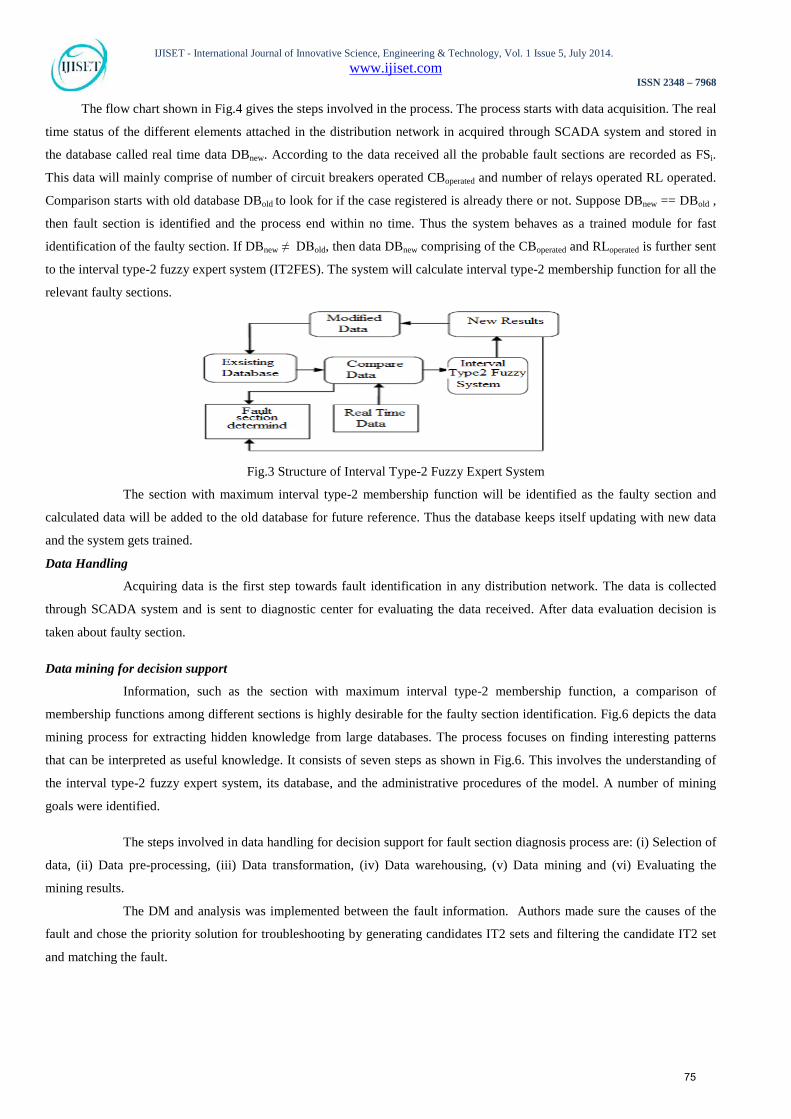
The flow chart shown in Fig.4 gives the steps involved in the process. The process starts with data acquisition. The real
time status of the different elements attached in the distribution network in acquired through SCADA system and stored in
the database called real time data DBnew. According to the data received all the probable fault sections are recorded as FSi.
This data will mainly comprise of number of circuit breakers operated CBoperated and number of relays operated RL operated.
Comparison starts with old database DBold to look for if the case registered is already there or not. Suppose DBnew == DBold ,
then fault section is identified and the process end within no time. Thus the system behaves as a trained module for fast
identification of the faulty section. If DBnew ≠ DBold, then data DBnew comprising of the CBoperated and RLoperated is further sent
to the interval type-2 fuzzy expert system (IT2FES). The system will calculate interval type-2 membership function for all the
relevant faulty sections.
Fig.3 Structure of Interval Type-2 Fuzzy Expert System
The section with maximum interval type-2 membership function will be identified as the faulty section and
calculated data will be added to the old database for future reference. Thus the database keeps itself updating with new data
and the system gets trained.
Data Handling
Acquiring data is the first step towards fault identification in any distribution network. The data is collected
through SCADA system and is sent to diagnostic center for evaluating the data received. After data evaluation decision is
taken about faulty section.
Data mining for decision support
Information, such as the section with maximum interval type-2 membership function, a comparison of
membership functions among different sections is highly desirable for the faulty section identification. Fig.6 depicts the data
mining process for extracting hidden knowledge from large databases. The process focuses on finding interesting patterns
that can be interpreted as useful knowledge. It consists of seven steps as shown in Fig.6. This involves the understanding of
the interval type-2 fuzzy expert system, its database, and the administrative procedures of the model. A number of mining
goals were identified.
The steps involved in data handling for decision support for fault section diagnosis process are: (i) Selection of
data, (ii) Data pre-processing, (iii) Data transformation, (iv) Data warehousing, (v) Data mining and (vi) Evaluating the
mining results.
The DM and analysis was implemented between the fault information. Authors made sure the causes of the
fault and chose the priority solution for troubleshooting by generating candidates IT2 sets and filtering the candidate IT2 set
and matching the fault.
75
IJISET - International Journal of Innovative Science, Engineering & Technology, Vol. 1 Issue 5, July 2014. www.ijiset.com
ISSN 2348 – 7968
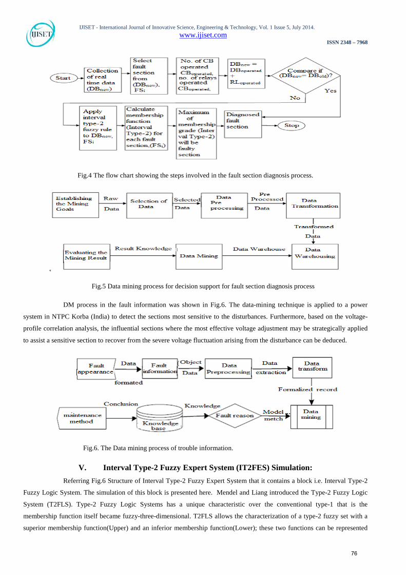
Fig.4 The flow chart showing the steps involved in the fault section diagnosis process.
Fig.5 Data mining process for decision support for fault section diagnosis process
DM process in the fault information was shown in Fig.6. The data-mining technique is applied to a power
system in NTPC Korba (India) to detect the sections most sensitive to the disturbances. Furthermore, based on the voltage-
profile correlation analysis, the influential sections where the most effective voltage adjustment may be strategically applied
to assist a sensitive section to recover from the severe voltage fluctuation arising from the disturbance can be deduced.
Fig.6. The Data mining process of trouble information.
V. Interval Type-2 Fuzzy Expert System (IT2FES) Simulation: Referring Fig.6 Structure of Interval Type-2 Fuzzy Expert System that it contains a block i.e. Interval Type-2
Fuzzy Logic System. The simulation of this block is presented here. Mendel and Liang introduced the Type-2 Fuzzy Logic
System (T2FLS). Type-2 Fuzzy Logic Systems has a unique characteristic over the conventional type-1 that is the
membership function itself became fuzzy-three-dimensional. T2FLS allows the characterization of a type-2 fuzzy set with a
superior membership function(Upper) and an inferior membership function(Lower); these two functions can be represented
76

IJISET - International Journal of Innovative Science, Engineering & Technology, Vol. 1 Issue 5, July 2014. www.ijiset.com
ISSN 2348 – 7968
each one by a type-1 fuzzy set membership function. The interval between these two functions represents the footprint of
uncertainty (FOU). The superior membership function is denoted by Upper membership Function (UMF), while the inferior
membership function is denoted by Lower Membership function (LMF). Interval type-2 membership function is shown in
Fig.7. The structure of a fuzzy logic type-2 system is shown in Fig.8.
Fuzzy logic type-2 system includes 4 components:
*Fuzzifier: Translates inputs (real values) to fuzzy values.
*Inference System: Applies a fuzzy reasoning mechanism to obtain a fuzzy output.
*Type Defuzzifier/Reducer: The defuzzifier translates one output to precise values; the type reducer transforms a Type-2
Fuzzy Set into a Type-1 Fuzzy Set.
*Knowledge Base: Contains a set of fuzzy rules, and a membership functions set known as the database.
An IT2FLS shown in Fig.8 is also characterized by fuzzy IF-THEN rules, but the membership functions of the
ITFLSs are now interval type-2 fuzzy sets (IT2FLSs).From Fig.7 ,it can be seen that the structure of an IT2FLS is very
similar to the structure of a T1FLS and the only difference exists in the output processing block. For a T1FLS, the output
processing block only contains a defuzzifier, but for an IT2FLS, the output processing block includes a type-reducer, which
maps a T2FS into a TIFS and a defuzzifier.
Fig.7: Type-2 Membership Function
Fig.8 Type-2 Fuzzy Logic System
Assume that there are M rules in the rule base, each of which has the following form:
𝑅𝑢𝑙𝑒 𝑘 ∶ 𝐼𝐹 𝑥1𝑖𝑠 �̃�1𝑘 𝑎𝑛𝑑 𝑥2𝑖𝑠 �̃�2𝑘 𝑎𝑛𝑑… . 𝑎𝑛𝑑 𝑥𝑝𝑖𝑠 �̃�𝑝𝑘 ,𝑇𝐻𝐸𝑁 𝑦 𝑖𝑠 �𝑤𝑘,𝑤�𝑘�
Where k =1,2,...M , p is the number of input variables in the antecedent part,
�̃�𝑖𝑘𝑘 𝑖 𝐴 (𝑖 = 1,2, . . . 𝑝, 𝑘 = 1,2. . .𝑀) are IT2FLS of the IF-part, and �𝑤𝑘,𝑤�𝑘� are the singleton lower and upper weighting
factors of the THEN-part. Once a crisp input X =(x1, x2 ,...., xp )T is applied to the IT2FLS, through the singleton fuzzifier
and the inference process, the firing strength of the k th rule which is an interval type-1 set can be obtained as
𝐹𝑘 = �𝑓𝑘, 𝑓̅𝑘�
Where𝑓𝑘 = 𝜇𝐴�1𝑘(𝑥1) ∗ 𝜇𝐴�2𝑘(𝑥2) ∗ … . .∗ 𝜇𝐴�𝑝𝑘�𝑥𝑝�
𝑓̅𝑘 = 𝜇𝐴�1𝑘(𝑥1) ∗ 𝜇𝐴�2𝑘(𝑥2) ∗ … . .∗ 𝜇𝐴�𝑝𝑘�𝑥𝑝�
77

IJISET - International Journal of Innovative Science, Engineering & Technology, Vol. 1 Issue 5, July 2014. www.ijiset.com
ISSN 2348 – 7968
In which 𝜇 and 𝜇 denote the grades of the lower and upper membership functions of IT2FSs and * denotes
minimum or product t-norm. To generate a crisp output, the outputs of the inference engine should be type reduced and
then defuzzified.
The type-1 (T1) and Interval Type-2 (IT2) FLC Design
For both Type-1 and Interval Type-2 FLCs triangular MFs were employed as they provide reduced
computation time. Choosing the number of MFs is important, as it determines the smoothness of the bit-rate granularity.
However, the number of MFs is directly proportional to the computation time and, hence, for this critical power system
application, a simplified representation is preferable. In the choice of the number of linguistic labels (or MFs) for both the
FLCs input and outputs, the number of linguistic labels were tuned to be the maximum number of labels the system can
afford to give a good diagnostic precision, while still enabling the system to achieve real-time performance. Fig.9a describes
the MFs for possible fault section FSi(CBoperated)which partition its range into four regions which are Low (L), Medium (M),
High (H) and Very High (VH). Fig.9b describes the MF for possible fault section FSi(RLoperated))which has two linguistic
labels which are Increasing Trend (I) and Decreasing Trend (D). The system output FSi (Possible fault section ith number) is
represented by 11 linguistic labels as shown in Fig.10 which are Negative Extremely High (NEH), Negative Very High
(NVH), Negative High (NH), Negative Medium (NM), Negative Low (NL), Zero (Z), Positive Low (PL), Positive Medium
(PM), Positive High (PH), Positive Very High (PVH), Positive Extremely High (PEH). The Type1 version of this system
employs the center-of sets defuzzification method. The IT2 FLC employs center-of sets type-reduction by using the iterative
Karnik-Mendel (KM) procedure. We have employed the iterative KM procedure as the number of used rules is quite small
(four rules). Given that the KM procedure is proven to converge in no more than M (number of fired rules, maximum four in
our case, if all rules fired) iterations to find the left end point of the type reduced set and no more than M iterations to find
the right end point of the type-reduced sets. Hence, the FLC will take a maximum of eight iterations (which is a very
acceptable number) to finish the type-reduction step. Thus, it has been feasible to employ the KM procedure and calculate
correct values of the type-reduced sets rather than approximate the type-reduced sets using the Wu-Mendel uncertainty
bounds method.
Fig.9. (a) Input Type-2 MFs for FSi(CBoperated) (b) Input Type-2 MFs for FSi(RLoperated)
Fig.10. Output Type-2 MFs for FSi (Possible fault section ith number).
Interval Type-2 FLS input and antecedent operations are shown in Fig.11, it shows that the Min-Pod
operations in antecedent signals are same as interval type-1 fuzzy logic system.
78

IJISET - International Journal of Innovative Science, Engineering & Technology, Vol. 1 Issue 5, July 2014. www.ijiset.com
ISSN 2348 – 7968
(a) (b) (c)
(d) (e) (f)
Fig.11 Type-2 FLS: input and antecedent operations.
(a) Singleton fuzzification with minimum t-norm; (b) singleton fuzzification with product t-norm; (c) NS type-
1 fuzzification with minimum t-norm; (d) NS type-1 fuzzification with product t-norm; (e) NS type-2 fuzzification with
minimum t-norm; (f) NS type-2 fuzzification with product t-norm.
The dark shaded regions depict the meet between input and antecedent.
Membership Formulation
The calculation will be determined by the pre fault and post fault status of the circuit breakers and the relays associated
with mentioned faulty section. If first step protection has operated then the signals in second and third step protections will be
ignored. If first and second step of protection have been isolated as the suspected fault section then the signals of third step
protection will be ignored. If all three step protections have not been isolated as the suspected fault section then there is no
fault in this particular section. The Upper membership function of FOU is denoted here as ‘U’ in upper case letter and Lower
membership function of FOU is denoted here as ‘L’ in upper case letter in the following equations.
FSUi, FSL
i = [FSiU (CBoperated), FSi
L (CBoperated)] ˅[FSiU(RLoperated), FSiL(RLoperated)]
= {Yi, μSU
(fault) (Yi), μSL
(fault) (Yi) | Yi ϵ DBnew}
[SUfault, SL
fault] = {FSiU, FSi
L}
[FSUi (CBoperated), FSL
i (CBoperated)] = {Yi, μUsCB
(fault) (FSi), μLsCB
(fault) (FSi)}
[FSUi (RLoperated), FSL
i (RLoperated)] = {Yi, μUsRL
(fault) (FSi), μLsRL
(fault) (FSi)}
Calculations based on the data of the circuit breakers operated. All the three steps k= 1.2 & 3 are considered FSi1, FSi
2 and FSi3
membership function is determined.
[FSUi (CBoperated), FSU
i (CBoperated)] = [FSUi1 (CBoperated), FSL
i1 (CBoperated) ] ˅ [FSU
i2(CBoperated), FSL
i2(CBoperated)] ˅
[FSUi3(CBoperated), FSL
i3(CBoperated)]
= { Yi , [μUsCB (fault) (Yi), μL
sCB (fault) (Yi)]}
[μUxCB (fault) (Yi), μL
xCB (fault) (Yi)] = [μU
x1
(fault) (Yi), μLx1(fault) (Yi)] + [μU
x2 (fault) (Yi), μL
x2 (fault) (Yi)] + [μU
x3(fault) (Yi), μL
x3(fault)
(Yi)]
79
IJISET - International Journal of Innovative Science, Engineering & Technology, Vol. 1 Issue 5, July 2014. www.ijiset.com
ISSN 2348 – 7968
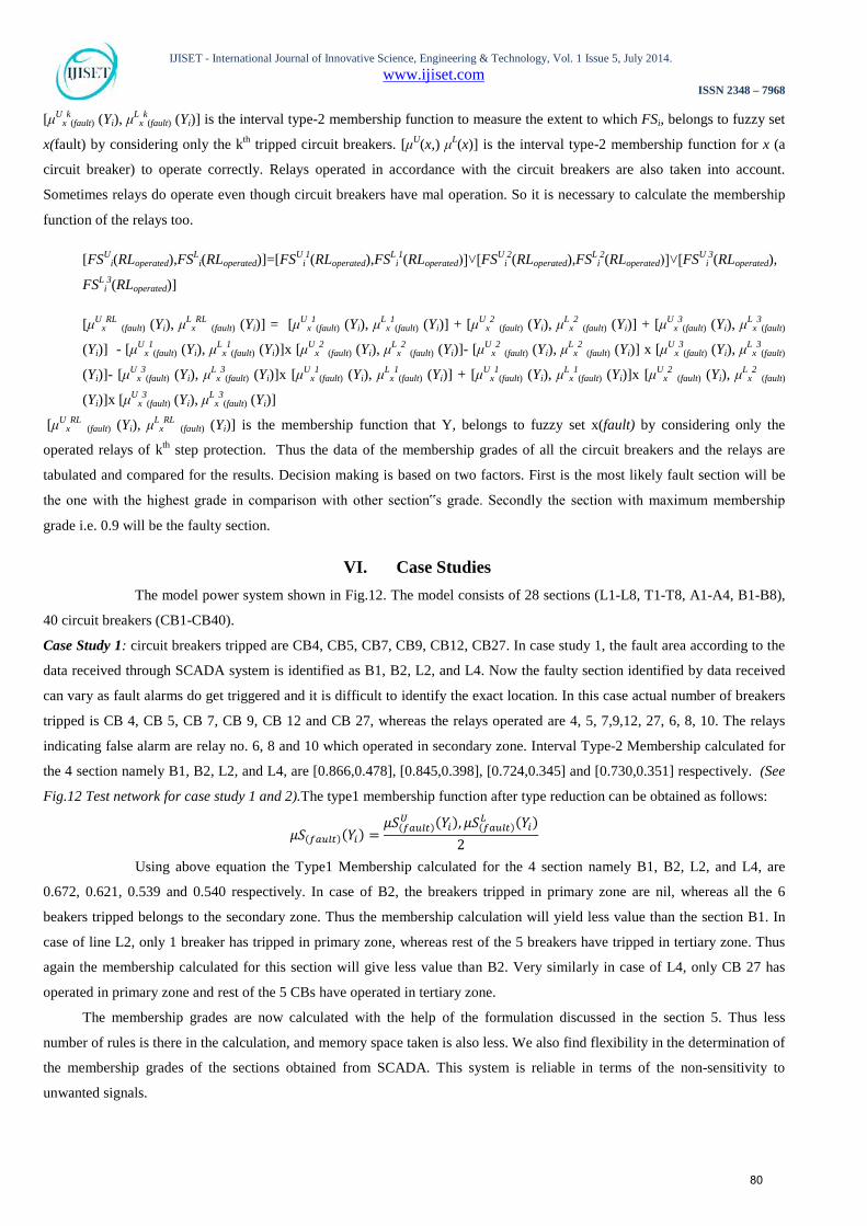
[μUxk(fault) (Yi), μL
xk(fault) (Yi)] is the interval type-2 membership function to measure the extent to which FSi, belongs to fuzzy set
x(fault) by considering only the kth tripped circuit breakers. [μU(x,) μL(x)] is the interval type-2 membership function for x (a
circuit breaker) to operate correctly. Relays operated in accordance with the circuit breakers are also taken into account.
Sometimes relays do operate even though circuit breakers have mal operation. So it is necessary to calculate the membership
function of the relays too.
[FSUi(RLoperated),FSL
i(RLoperated)]=[FSUi1(RLoperated),FSL
i1(RLoperated)]˅[FSU
i2(RLoperated),FSL
i2(RLoperated)]˅[FSU
i3(RLoperated),
FSLi3(RLoperated)]
[μUxRL (fault) (Yi), μL
xRL (fault) (Yi)] = [μU
x1
(fault) (Yi), μLx1(fault) (Yi)] + [μU
x2 (fault) (Yi), μL
x2 (fault) (Yi)] + [μU
x3(fault) (Yi), μL
x3(fault)
(Yi)] - [μUx1(fault) (Yi), μL
x1
(fault) (Yi)]x [μUx2 (fault) (Yi), μL
x2 (fault) (Yi)]- [μU
x2 (fault) (Yi), μL
x2 (fault) (Yi)] x [μU
x3(fault) (Yi), μL
x3(fault)
(Yi)]- [μUx3(fault) (Yi), μL
x3
(fault) (Yi)]x [μUx1
(fault) (Yi), μLx1(fault) (Yi)] + [μU
x1(fault) (Yi), μL
x1(fault) (Yi)]x [μU
x2 (fault) (Yi), μL
x2 (fault)
(Yi)]x [μUx3(fault) (Yi), μL
x3
(fault) (Yi)]
[μUxRL (fault) (Yi), μL
xRL (fault) (Yi)] is the membership function that Y, belongs to fuzzy set x(fault) by considering only the
operated relays of kth step protection. Thus the data of the membership grades of all the circuit breakers and the relays are
tabulated and compared for the results. Decision making is based on two factors. First is the most likely fault section will be
the one with the highest grade in comparison with other section‟s grade. Secondly the section with maximum membership
grade i.e. 0.9 will be the faulty section.
VI. Case Studies The model power system shown in Fig.12. The model consists of 28 sections (L1-L8, T1-T8, A1-A4, B1-B8),
40 circuit breakers (CB1-CB40).
Case Study 1: circuit breakers tripped are CB4, CB5, CB7, CB9, CB12, CB27. In case study 1, the fault area according to the
data received through SCADA system is identified as B1, B2, L2, and L4. Now the faulty section identified by data received
can vary as fault alarms do get triggered and it is difficult to identify the exact location. In this case actual number of breakers
tripped is CB 4, CB 5, CB 7, CB 9, CB 12 and CB 27, whereas the relays operated are 4, 5, 7,9,12, 27, 6, 8, 10. The relays
indicating false alarm are relay no. 6, 8 and 10 which operated in secondary zone. Interval Type-2 Membership calculated for
the 4 section namely B1, B2, L2, and L4, are [0.866,0.478], [0.845,0.398], [0.724,0.345] and [0.730,0.351] respectively. (See
Fig.12 Test network for case study 1 and 2).The type1 membership function after type reduction can be obtained as follows:
𝜇𝑆(𝑓𝑎𝑢𝑙𝑡)(𝑌𝑖) =𝜇𝑆(𝑓𝑎𝑢𝑙𝑡)
𝑈 (𝑌𝑖), 𝜇𝑆(𝑓𝑎𝑢𝑙𝑡)𝐿 (𝑌𝑖)
2
Using above equation the Type1 Membership calculated for the 4 section namely B1, B2, L2, and L4, are
0.672, 0.621, 0.539 and 0.540 respectively. In case of B2, the breakers tripped in primary zone are nil, whereas all the 6
beakers tripped belongs to the secondary zone. Thus the membership calculation will yield less value than the section B1. In
case of line L2, only 1 breaker has tripped in primary zone, whereas rest of the 5 breakers have tripped in tertiary zone. Thus
again the membership calculated for this section will give less value than B2. Very similarly in case of L4, only CB 27 has
operated in primary zone and rest of the 5 CBs have operated in tertiary zone.
The membership grades are now calculated with the help of the formulation discussed in the section 5. Thus less
number of rules is there in the calculation, and memory space taken is also less. We also find flexibility in the determination of
the membership grades of the sections obtained from SCADA. This system is reliable in terms of the non-sensitivity to
unwanted signals.
80

IJISET - International Journal of Innovative Science, Engineering & Technology, Vol. 1 Issue 5, July 2014. www.ijiset.com
ISSN 2348 – 7968
So Maximum membership calculated belongs to B1 and so this is the most probable faulty section of all the given
zones.
Case Study 2: circuit breakers operated are CB19, CB20, CB32, CB33, CB31, CB34, CB35, CB36, CB37,CB39 & CB40. In
case study 2, the fault area according to the data received through SCADA system is identified as B7, B8, L5, L6, L7, L8, T7
and T8. Now the faulty section identified by data received can vary as fault alarms do get triggered and it is difficult to identify
the exact location. In this case actual number of breakers tripped is CB19, CB20, CB32, CB33, CB34, CB35, CB36, CB37 &
CB39.The relays indicating false alarm are relay no. 31 and 40, which operated in secondary zone. Interval Type-2
Membership calculated for the 8 section namely B7, B8, L5, L6, L7, L8, T7 and T8 are [0.822, 0.453], [0.898, 0.498], [0.898,
0.498], [0.754, 0.445],[0.898, 0.498], [0.754, 0.445],[0.898, 0.498],[0.898, 0.498] respectively. Using above equation the
Type-1 Membership calculated for the 4 section namely B7, B8, L5, L6, L7, L8, T7 and T8, are 0.632, 0.694, 0.694, 0.599,
0.694, 0.599, 0.694 and 0.694 respectively.
Fig.12 Test Circuit for Case Study
Table 1
Membership Grade for Case Study 1
81

IJISET - International Journal of Innovative Science, Engineering & Technology, Vol. 1 Issue 5, July 2014. www.ijiset.com
ISSN 2348 – 7968
Fig.13 Grades assigned to all sections (Case1)
Table 2
Membership Grade for Case Study 2
Fig.14 Grades assigned to all sections (Case2)
In this case study the sections with maximum membership value have been identified as B8, L5, L7, T7 and T8. Here as
it is clear from the fuzzy calculation the faulty section B7, L6 and L8 are just the part of the section but not the faulted one just
because the grades assigned to them is minimum in comparison to rest of the sections. As we compare the data, decision can
be quickly made about the faulty section. This calculation will be recorded in the existing database. Thus a database will be
constantly updated and can be assessed for the future reference.
VII. Conclusion This paper describes Fault Section Diagnosis of Power Distribution System using Interval Type-2 Fuzzy Data
mining. The trained database compares the real time data with the existing data and gets the decision. For new data set
interval type-2 fuzzy system is being used to identify the faulty section. Interval type-2 membership grades calculated for
various sections gives the most possible fault section. Three steps are discussed in the interval type-2 membership
formulation of the circuit breakers and the relays to get accurate answer. This database will act as the trainer to the interval
type-2 fuzzy expert system. A rich history of faulty area will enhance the performance of the Interval Type-2 Fuzzy Fault
82

IJISET - International Journal of Innovative Science, Engineering & Technology, Vol. 1 Issue 5, July 2014. www.ijiset.com
ISSN 2348 – 7968
Identification System (IT2FFIS). Fault section location aims to identify the faulty area in the power system using the post
fault status of protective relays and circuit breakers and diagnose the cause of a fault that has occurred. Restoration cost can
be significantly reduced by accurately identifying a fault location and its cause, which also reduces the restoration time of the
faulty section. Decision making is based on two factors. First is the most likely fault section will be the one with the highest
grade in comparison with other section’s grade. Secondly the section with maximum membership grade i.e. 0.7 will be the
faulty section.
References 1. L. Xu, M.Y. Chow and L. S. Taylor, (Feb 2007) “Power Distribution Fault Cause Identification with Imbalanced Data Using the Data Mining
Based Fuzzy Classification E-Algorithm”, IEEE Transaction on Power Systems, Vol.22, No.1, pp.164-171.
2. L. Xu and M.Y. Chow, (2006) “A classification approach for power distribution systems fault cause identification”, IEEE Transactions on Power
Systems, Vol. 21, No. 1, pp. 53-60.
3. Hong-Chan Chin, (2003) “Fault Section Diagnosis of Power System Using Fuzzy Logic”, IEEE Trans Power System, Vol. 18, No. 1, pp. 245-250.
4. Xiaohui Zhul , Xin LuI, Dong Liu, Bingda Zhang, (2010) “An Improved Fault Locating System of Distribution Network based on Fuzzy
Identification”, China International Conference on Electricity Distribution, pp. 1-6, 13-16 Sept. 2010, Nanjing.
5. Fábio Bertequini leão, Rodrigo A. F. Pereira and José R. S. Mantovani, (2009) “Fault section estimation in electric power systems using an
artificial immune system algorithm”, International Journal of Innovations in Energy Systems and Power, Vol. 4, No. 1, pp. 14-21.
6. P.K. Dash, H.S. Behera, I.W.C. Lee, (2007) “Time sequence data mining using time–frequency analysis and soft computing techniques”, Appl.
Soft Comput. J., doi:10.1016/j.asoc.2007.01.001
7. A. Pellicel, et.al. (2011) “Intelligent Data Mining for Turbo-Generator Predictive Maintenance: An Approach in Real-World”, Proc. of the
International Workshop on Soft Computing Applications and Knowledge Discovery (SCAKD 2011), Moscow, Russia, June 25.
8. He YueShun, and Ding QiuLin. “Fault Mode Analyze of Power System Based on Data Mining”. Proc. of the 2009 International Symposium on
Web Information Systems and Applications (WISA’09) Nanchang, P. R. China, May 22-24, 2009, pp. 318-320
9. U. M. Fayyad, et. al. “Advances in Knowledge Discovery and Data Mining. Menlo Park, CA: AAAI/MIT Press, 1996.
10. K. J. Cios, W. Pedrycz, and R. Swiniarski, Data Mining Methods for Knowledge Discovery. Dordrecht, The Netherlands: Kluwer, 1998.
11. C. K. Shin, S. J. Yu, U. T. Yun, and H. K. Kim, “A hybrid approach of neural network and memory based learning to data mining,” IEEE Trans.
Neural Networks, Vol. 11, pp. 637–646, 2000.
12. N. N. Karnik and J. M. Mendel, “Type-2 fuzzy logic systems: Type-reduction,” in IEEE Syst., Man, Cybern. Conf., San Diego, CA, Oct. 1998.
13. N. N. Karnik and J. M. Mendel,“Applications of type-2 fuzzy logic systems to forecasting of time series,” Inform. Sci., vol. 120, pp. 89–111, 1999.
14. Satya Prakash and S.C.Gupta, “Fuzzy Logic Based Trained Fault Locating Mechanism in Power Distribution Network” International Journal of
Emerging Technology and Advanced Engineering (ISSN 2250-2459), Vol. 2, Issue 7, pp.129-135, July 2012
15. N. N. Karnik and J. M. Mendel, “Type-2 fuzzy logic systems,” IEEE Trans. Fuzzy Syst., Vol. 7, pp. 643–658, Dec. 1999.
16. J. M. Mendel and R. I. B. John, “Type-2 fuzzy sets made simple”, IEEE Trans. on Fuzzy Syst., Vol. 16, No. 2, pp. 117-127, 2002.
17. H. Shu, Q. Liang and J. Gao, (2008) “Wireless sensor network lifetime analysis using interval type-2 fuzzy logic systems”, IEEE Trans. on Fuzzy
Syst., Vol. 16, No. 2, pp. 416-427.
18. Q. Liang and J. M. Mendel, “Interval type-2 fuzzy logic systems: Theory and design”, IEEE Trans. on Fuzzy Logic Systems”, Vol. 8, No. 5, pp.
535-550, 2000.
19. D.Wu and W.Tan, (April 2005) “Type-2 FLS Modeling Capability Analysis”, IEEE Int. Conf. on Fuzzy Syst., pp. 242-247, Reno, USA.
20. H. Wu and J. M. Mendel, (2002) “Uncertainty bounds and their use in the design of interval type-2 fuzzy logic systems”, IEEE Trans. on Fuzzy
Syst., Vol. 10, No. 5, pp. 622-639.
--------------------
83