IJAuERD - ANALYSIS OF LEAF SPRING CONDITIONS ......Leaf springs are made from flat plates, and have...
8
ANALYSIS OF LEAF SPRING CONDITIONS FOR HEAVY DUTY VEHICLE VANDANA JAIN & TRAPTI SHARMA Assistant Professor, Automobile Engineering Department, RJIT, Tekanpur, India ABSTRACT This paper aims to analyse leaf spring and compare nipping and non-nipping of leaf spring condition. For this purpose, multi leaf springs, made up of structural steel have been selected. As leaf spring contributes to considerable amount of weight of the vehicle, and hence needs to be strong enough. Leaf spring is a simple form of suspension spring and is subjected to varying stress cycles leading to fatigue failure. The focus is on to reduce the weight of suspension system, while maintaining the strength. The behavior of a vehicle is directly affected by its suspension system, i.e. vibration characteristics, riding performance and comfort that are directly related to its suspension system. As per the previous studies, two types of leaf springs are generally used in automobile i.e. with nipping and without nipping. Here, a comparison is presented to understand the behavior of stress, deformation and failure criterion. As leaf spring plays a vital role not only in automobile industry, but also many other areas, where impact load is the criteria for failure. Hence, its analysis is essential to predict its behavior under loading condition. The leaf spring of steel is designed for a heavy duty vehicle, and is modeled in SOLID WORK 13. The designed leaf spring is then analyzed by ANSYS 14 to study various stresses, induced due to the loading over it. Analysis was done with all boundary conditions, which includes loading and constraints. A comparison of leaf spring with nipping and without nipping was carried out. KEYWORDS: Leaf Spring, Nipping, Ansys 14, Mesh, Fatigue & Factor of Safety INTRODUCTION A spring is defined as an elastic body, whose function is to distort when loaded, on removal of load to recover its original shape and retain the original position. Leaf springs (also known as flat springs)absorb the vehicle’s vibrations, shocks and bump loads by means of spring deflections, so that the potential energy is stored in the leaf spring and then relieved slowly. It is an important part of the suspension system, which allows vertical tire and wheel movement in vehicles and carries the weight of the vehicle. When additional load is placed on a spring, because of more passenger or object or because of tire meets a bump, the spring absorbs this load, by deforming it temporarily and after the removal of load, it regains its shape. These are normally of semi elliptical shape, having a main leaf with an eye at each end. Multi leafs are assembled to from a group of leaves of different lengths and made stronger by making the leaves thicker. The flexibility of leaf spring can be increased by increasing the length of leaves. The entire vehicle load rests on leaf spring, which is mounted on the axle of the vehicle. One of its ends connected to frame i.e. front end by a simple in joint, while other end i.e. rear end is connected by a shackle. Shackle is in the form of flexible link, which is connected between rear eye of leaf spring and frame. As the projections come on the road’s surface, vehicle starts moving up and down, this leads deflection in leaf spring, as the spring goes under deflection the length between both the eyes change. If both the ends of spring will be fixed, then spring will not be able to accommodate this deflection in the form of change in length. The shackle is provided at one of its end to provide flexible connection to accommodate this change in length. The front end of the leaf spring is fixed i.e. motion in all the directions are constrained, International Journal of Automobile Engineering Research and Development (IJAuERD) ISSN 2277-4785 Vol. 3, Issue 1, Mar 2013, 97-104 © TJPRC Pvt. Ltd.
Transcript of IJAuERD - ANALYSIS OF LEAF SPRING CONDITIONS ......Leaf springs are made from flat plates, and have...

ANALYSIS OF LEAF SPRING CONDITIONS FOR HEAVY DUTY V EHICLE
VANDANA JAIN & TRAPTI SHARMA
Assistant Professor, Automobile Engineering Department, RJIT, Tekanpur, India
ABSTRACT
This paper aims to analyse leaf spring and compare nipping and non-nipping of leaf spring condition. For this
purpose, multi leaf springs, made up of structural steel have been selected. As leaf spring contributes to considerable
amount of weight of the vehicle, and hence needs to be strong enough. Leaf spring is a simple form of suspension spring
and is subjected to varying stress cycles leading to fatigue failure. The focus is on to reduce the weight of suspension
system, while maintaining the strength. The behavior of a vehicle is directly affected by its suspension system, i.e.
vibration characteristics, riding performance and comfort that are directly related to its suspension system.
As per the previous studies, two types of leaf springs are generally used in automobile i.e. with nipping and
without nipping. Here, a comparison is presented to understand the behavior of stress, deformation and failure criterion. As
leaf spring plays a vital role not only in automobile industry, but also many other areas, where impact load is the criteria
for failure.
Hence, its analysis is essential to predict its behavior under loading condition. The leaf spring of steel is designed
for a heavy duty vehicle, and is modeled in SOLID WORK 13. The designed leaf spring is then analyzed by ANSYS 14 to
study various stresses, induced due to the loading over it. Analysis was done with all boundary conditions, which includes
loading and constraints. A comparison of leaf spring with nipping and without nipping was carried out.
KEYWORDS: Leaf Spring, Nipping, Ansys 14, Mesh, Fatigue & Factor of Safety
INTRODUCTION
A spring is defined as an elastic body, whose function is to distort when loaded, on removal of load to recover its
original shape and retain the original position. Leaf springs (also known as flat springs)absorb the vehicle’s vibrations,
shocks and bump loads by means of spring deflections, so that the potential energy is stored in the leaf spring and then
relieved slowly. It is an important part of the suspension system, which allows vertical tire and wheel movement in
vehicles and carries the weight of the vehicle. When additional load is placed on a spring, because of more passenger or
object or because of tire meets a bump, the spring absorbs this load, by deforming it temporarily and after the removal of
load, it regains its shape. These are normally of semi elliptical shape, having a main leaf with an eye at each end. Multi
leafs are assembled to from a group of leaves of different lengths and made stronger by making the leaves thicker. The
flexibility of leaf spring can be increased by increasing the length of leaves.
The entire vehicle load rests on leaf spring, which is mounted on the axle of the vehicle. One of its ends connected
to frame i.e. front end by a simple in joint, while other end i.e. rear end is connected by a shackle. Shackle is in the form of
flexible link, which is connected between rear eye of leaf spring and frame. As the projections come on the road’s surface,
vehicle starts moving up and down, this leads deflection in leaf spring, as the spring goes under deflection the length
between both the eyes change. If both the ends of spring will be fixed, then spring will not be able to accommodate this
deflection in the form of change in length. The shackle is provided at one of its end to provide flexible connection to
accommodate this change in length. The front end of the leaf spring is fixed i.e. motion in all the directions are constrained,
International Journal of Automobile Engineering Research and Development (IJAuERD) ISSN 2277-4785 Vol. 3, Issue 1, Mar 2013, 97-104 © TJPRC Pvt. Ltd.

98 Vandana Jain & Trapti Sharma
while rear eye is free in X-direction and connected to shackle. As the load applies on the axle, it transfers to leaf spring and
deflect it in the direction perpendicular to the load applied.
LITERATURE REVIEW
• M.VENKATESAN presented the design and experimental study of leaf spring made up of composite glass fiber
reinforced polymer for light weight vehicles. Load carrying capacity, stiffness and weight savings are compared
with that of steel leaf spring. Analysis with ANSYS 10 and experimental study has shown that the composite
spring has 67.35%less stress, 64.95% higher stiffness and 126.98% higher natural frequency as compare to the
existing steel leaf spring. By optimizing the composite leaf spring, a weight reduction of 76.4% is achieved.
• Subhash Chandrabose presented a brief study on analysis, design and fabrication of parabolic leaf spring. Along
with the study a finite element model has been deployed to optimize and improve the design.
In the same direction [3], B. Vijay Lakshmi has shown the static and dynamic analysis of composite spring for
heavy duty vehicle. The analysis has been done to compare the weight saving, load carrying capacity and stiffness for leaf
spring of different material E-GLASS/EPOXY, C- GLASS/EPOXY, S- GLASS/EPOXY and steel leaf spring. As per the
result, composite material posses better performance than that of the steel leaf spring.
An extension in above work was done by [4] jadhav Mahesh. He presented an analysis of mono leaf spring used
for Maruti 800 vehicle and concluded, as the development of mono leaf spring of composite material with constant cross
section area in which, stress level at any point in the leaf is considered constant, because of parabolic type of thickness that
was proved to be very effective.
WORKING PRINCIPAL OF SPRING
The suspension leaf spring is one of the potential items for the weight absorption in automobile, as it accounts ten
to twenty percent of the un-sprung weight. In the design of springs, strain energy becomes the major factor. The
relationship of the specific strain energy can be expressed as
U= σ²/ρE
Where σ is the strength, ρ is the density and E is the Young’s Modulus of the spring material. It can be clearly
observed from the above relation that the material having lower modulus of elasticity and density will have a greater
specific strain energy capacity.
DESIGN OF LEAF SPRING
Leaf springs are made from flat plates, and have many advantages over helical spring which is widely used in
automobile industry. The ends of the leaf spring can be guided along a definite path, as it deflects and acts as structural
member along with absorbing energy. It can carry different types of load, such as lateral loads, brake torque, driving torque
and shock as well.
Let
Thickness of plate = t
Width of plate = b, and

Analysis of Leaf Spring Conditions for Heavy Duty Vehicle 99
Length of plate = L
Effective length of spring = 2Lı-2l/3
Length of smallest leaf = (Effective length/n-1) + ineffective length
Length of next leaf = (Effective length/n-1)×2 + ineffective length
Length of (n-1)th leaf = (Effective length/n-1)(n-1) + Ineffective length
Length of Master leaf = 2Lı+Π(d+t) ×2
Maximum bending moment, M = WL
Section modulus, Z = bt²/6
Bending stress, σ = M/Z = 6WL/nbt
SPECIFICATIONS OF SPRING
Table 1: Specifications of Leaf Springs
S. No Parameter value 1. Total length of spring eye to eye 1130 mm 2. No of full length leaf 01 3. Total number of leaf 04 4. Thickness of leaf 10 mm 5. Width of leaf 80 mm 6. Radius of curvature 3125 mm 7. Maximum load given on spring 2000 N 8. Material Structural steel
NIPPING OF LEAF SPRING
Leaf spring is normally an assembly of two or more leaves. Largest one is known as master leaf. In case of nipped
leaf spring, the master leaf has slightly larger curvature as compare to leaf which is just below the master leaf. This
difference creates a gap between the two leaves as indicated in the figure 1. During the assembly of spring, by tightening
the central bolt, an initial bent is created. Because of tightening, a little compressive stress is introduced at the inside
curvature of the master leaf, while at the outside of the curvature, tensile stress is produced. These stresses are known as
initial stresses in the master leaf. Apart from these stresses an additional leaf is also placed beneath. The master leaf has
tendency to flatten out, because of this, the additional leaf resulted stress pattern will be reverse of that master leaf. Tensile
stress is produced at the inner surface of curvature, and compressive stress is produced at the outer surface of curvature.
Hence, in the loading condition of spring, both master leaf as well as additional leaf is subjected to tensile stress at the
inner surface of curvature and compressive stress at the outer surface of curvature. Because of the opposite nature of initial
stress and loading stress, the master leaf experiences less stress on both the surfaces. In additional leaf, due to the same
nature of initial as well as loading stress, it experience more stress as compared to master leaf. But, it is to be noted that the
higher stress of the additional leaf is shared between all other leaves than the master leaf. This process of relieving stress in
the master leaf is known as “Nipping of leaf spring” . All the leaves of a multi leaf spring have certain amount of nipping,
because of this; there will be a gap between the leaves. This gap is resulted in uniform distribution of stress and
accumulated dusts can also be cleaned.

100
Figure 1
EXPRESSION FOR INITIAL GAP OR NIP
C= 2WL³/2nEbt³
Load on clip bolt, Wb = 2Nf.Ng.W/n(2Ng+3Nf)
Final Stress, σ = M/Z = 6WL/nbt²
MATERIAL
The basic requirements of a leaf spring steel is that the selected grade of steel must have sufficient harden
ability for the size involved, to ensure a full martensitic structure throughout the entire leaf section.
hardness in case of thick leaf sections, higher alloy content is necessary.
ALLOY STEEL.
The structure of material and its characteristics are related to performance of spring and determined first.
The leaf springs are specially designed to absorb vibrations, shocks and bump loads induce due to irregularities of
the road in the form of spring deflection. Because
This ability of spring to store and absorb more strain energy
MODELING OF LEAF SPRING
In the present work, the 3D geometric model of the leaf spring
using the above design data, which was without nipping. Same data has been used to design a leaf spring with applying
nipping, as per equation 1 for comparison of b
software. Figures 2 (a) & (b) are showing solid models
As the modeling of the leaf spring
were made during the analysis:
• The leaf spring is considered as
• The problem domain is considered as axis
• Inertia & body force effects are negligible during the analysis.
1: Representation of Nipping Between Two Leaves
EXPRESSION FOR INITIAL GAP OR NIP
= 2Nf.Ng.W/n(2Ng+3Nf)
= M/Z = 6WL/nbt²
The basic requirements of a leaf spring steel is that the selected grade of steel must have sufficient harden
to ensure a full martensitic structure throughout the entire leaf section.
hardness in case of thick leaf sections, higher alloy content is necessary. The material used for the experimental work is
erial and its characteristics are related to performance of spring and determined first.
The leaf springs are specially designed to absorb vibrations, shocks and bump loads induce due to irregularities of
form of spring deflection. Because of the deflection, potential energy is stored in spring and released slowly.
This ability of spring to store and absorb more strain energy ensures efficient suspension system.
he 3D geometric model of the leaf spring of a heavy weight commercial vehicle
above design data, which was without nipping. Same data has been used to design a leaf spring with applying
for comparison of both the models. The models are prepared by using SOLIDWORK
are showing solid models of leaf springs, with and without consideration of nipping.
leaf spring completed, the analysis was carried out on ANSYS
is considered as homogenous and isotropic.
The problem domain is considered as axis- symmetric.
body force effects are negligible during the analysis.
Vandana Jain & Trapti Sharma
The basic requirements of a leaf spring steel is that the selected grade of steel must have sufficient hardening
to ensure a full martensitic structure throughout the entire leaf section. To ensure the adequate
The material used for the experimental work is
erial and its characteristics are related to performance of spring and determined first.
The leaf springs are specially designed to absorb vibrations, shocks and bump loads induce due to irregularities of
potential energy is stored in spring and released slowly.
efficient suspension system.
of a heavy weight commercial vehicle is developed
above design data, which was without nipping. Same data has been used to design a leaf spring with applying
prepared by using SOLIDWORK modeling
with and without consideration of nipping.
carried out on ANSYS-14. Following assumptions
Analysis of Leaf Spring Conditions for Heavy Duty Vehicle
Figure 2: (A) Model of Leaf Spring without Nipping (B)
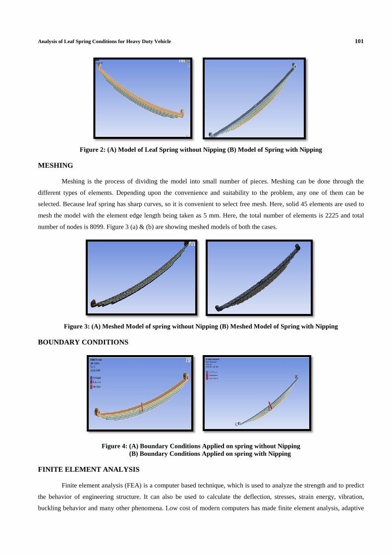
MESHING
Meshing is the process of dividing the model into small number of pieces. Meshing can be done
different types of elements. Depending upon the convenience and suitability to the problem
selected. Because leaf spring has sharp curves
mesh the model with the element edge length
number of nodes is 8099. Figure 3 (a) &
Figure 3: (A) Meshed Model of
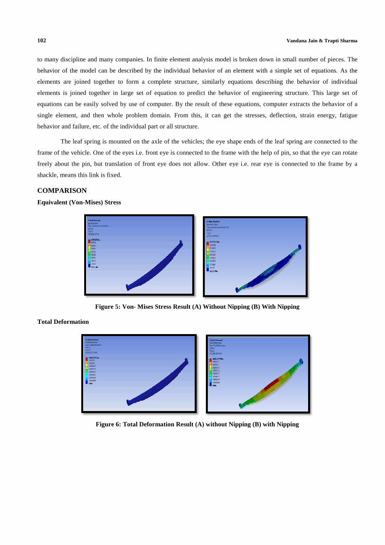
BOUNDARY CONDITIONS
Figure 4: (A) Boundary (B) Boundary
FINITE ELEMENT ANALYSIS
Finite element analysis (FEA) is a computer based technique
the behavior of engineering structure. It can also be used to calculate the deflection, stresses, strain energy, vibration,
buckling behavior and many other phenomena. Low cost of modern computers has made finite element analysis
Heavy Duty Vehicle
of Leaf Spring without Nipping (B) Model of Spring with Nipping
Meshing is the process of dividing the model into small number of pieces. Meshing can be done
different types of elements. Depending upon the convenience and suitability to the problem
Because leaf spring has sharp curves, so it is convenient to select free mesh. Here,
element edge length being taken as 5 mm. Here, the total number of elements is
3 (a) & (b) are showing meshed models of both the cases.
Model of spring without Nipping (B) Meshed Model of Spring with Nipping
Boundary Conditions Applied on spring without Nipping Boundary Conditions Applied on spring with Nipping
lement analysis (FEA) is a computer based technique, which is used to analyze the strength and to predict
the behavior of engineering structure. It can also be used to calculate the deflection, stresses, strain energy, vibration,
behavior and many other phenomena. Low cost of modern computers has made finite element analysis
101
of Spring with Nipping
Meshing is the process of dividing the model into small number of pieces. Meshing can be done through the
different types of elements. Depending upon the convenience and suitability to the problem, any one of them can be
, solid 45 elements are used to
number of elements is 2225 and total
Model of Spring with Nipping
without Nipping with Nipping
which is used to analyze the strength and to predict
the behavior of engineering structure. It can also be used to calculate the deflection, stresses, strain energy, vibration,
behavior and many other phenomena. Low cost of modern computers has made finite element analysis, adaptive
102
to many discipline and many companies. In
behavior of the model can be described by the individual behavior of an element with a simple set of equations. As the
elements are joined together to form
elements is joined together in large set of equation to predict the behavior of engineering structure. This large set of
equations can be easily solved by use of computer.
single element, and then whole problem domain
behavior and failure, etc. of the individual part or all
The leaf spring is mounted on the axle of the vehicles; the
frame of the vehicle. One of the eyes i.e. front eye is connected to the frame with the help of pin
freely about the pin, but translation of front eye does not allow. Other eye i.e. rear eye is connected to t
shackle, means this link is fixed.
COMPARISON
Equivalent (Von-Mises) Stress
Figure 5: Von- Mises Stress Result (A) Without Nipping (B) With Nipping
Total Deformation
Figure 6: Total Deformation Result (A) without Nipping (B) with
to many discipline and many companies. In finite element analysis model is broken down in small number of pieces. The
scribed by the individual behavior of an element with a simple set of equations. As the
elements are joined together to form a complete structure, similarly equations describing the behavior of individual
joined together in large set of equation to predict the behavior of engineering structure. This large set of
equations can be easily solved by use of computer. By the result of these equations, computer extracts the behavio
whole problem domain. From this, it can get the stresses, deflection, strain energy, fatigue
the individual part or all structure.
The leaf spring is mounted on the axle of the vehicles; the eye shape ends of the leaf spring a
frame of the vehicle. One of the eyes i.e. front eye is connected to the frame with the help of pin
but translation of front eye does not allow. Other eye i.e. rear eye is connected to t
Mises Stress Result (A) Without Nipping (B) With Nipping
Deformation Result (A) without Nipping (B) with Nipping
Vandana Jain & Trapti Sharma
finite element analysis model is broken down in small number of pieces. The
scribed by the individual behavior of an element with a simple set of equations. As the
similarly equations describing the behavior of individual
joined together in large set of equation to predict the behavior of engineering structure. This large set of
computer extracts the behavior of a
deflection, strain energy, fatigue
eye shape ends of the leaf spring are connected to the
frame of the vehicle. One of the eyes i.e. front eye is connected to the frame with the help of pin, so that the eye can rotate
but translation of front eye does not allow. Other eye i.e. rear eye is connected to the frame by a
Mises Stress Result (A) Without Nipping (B) With Nipping
Nipping

Analysis of Leaf Spring Conditions for Heavy Duty Vehicle
Safety Factor
Figure 7:
Table 2:
Results without Nipping1. Equivalent stress (Von2. Total Deformation3. Safety Factor
Results with Nipping1. Equivalent stress2. Total Deformation4. Safety Factor
CONCLUSIONS
The 3-D models of structural steel leaf spring
structural steel leaf spring with and without consideration of nipping
deformation and factor of safety.
From the results, it is observed that the leaf spring
without nipping leaf spring with similar design specifications and material.
same, while minimum factor safety is less in without nipping leaf spring
So, it can be concluded that in case of nipped leaf spring
deformation of adjacent leaf. Hence, the
stress is also less in nipped leaf spring.
REFERENCES
1. M. Venkatesan and D.HelmenDevaraj, “
International Journal of Modern Engineering Research (IJMER)
pp-213-218
2. SubhashChandrabose, C. Thamotharan, P. Naveenchandran and R. Anbazhagan, “D
Analysis of a Parabolic Leaf Spring”, Middle
1596, 2014.
3. B.VijayaLakshmiI and Satyanarayana, “Static and Dynamic Analysis on Composite leaf Spring in Heavy
Heavy Duty Vehicle
7: Safety Factor (A) without Nipping (B) with Nipping
Table 2: Analysis Result for Both the Cases of Leaf Spring
Results without Nipping Minimum Value Maximum Value1. Equivalent stress (Von- mises) 2.633e07Pa 2.2079e08Pa2. Total Deformation 8.467e-05 meter 0.0007603meter
1.1329 15 Results with Nipping Minimumvalue Maximum Value
1. Equivalent stress 1.326e07 Pa 1.1933e08 Pa. Total Deformation 4.644e-5 meter 0.000107 meter
2.0851 15
D models of structural steel leaf springs were analyzed using ANSYS. A compar
and without consideration of nipping, with respect to equivalent stress (von
From the results, it is observed that the leaf spring with nipping has less stress and total deformation as compare to
without nipping leaf spring with similar design specifications and material. Maximum factor of
while minimum factor safety is less in without nipping leaf spring, as compared to the other
it can be concluded that in case of nipped leaf spring, the gap between each leaf does not constraint the
the deformation is more as compare to without nipped spring
Venkatesan and D.HelmenDevaraj, “Design and analysis of composite leaf spring in light vehicle”,
International Journal of Modern Engineering Research (IJMER) ISSN: 2249-6645, Vol.2, Issue.1, Jan
SubhashChandrabose, C. Thamotharan, P. Naveenchandran and R. Anbazhagan, “D
Analysis of a Parabolic Leaf Spring”, Middle-East Journal of Scientific ResearchISSN 1990
B.VijayaLakshmiI and Satyanarayana, “Static and Dynamic Analysis on Composite leaf Spring in Heavy
103
Factor (A) without Nipping (B) with Nipping
Maximum Value 2.2079e08Pa
0.0007603meter
Maximum Value 1.1933e08 Pa
0.000107 meter
A comparison was made between
equivalent stress (von- mises), total
with nipping has less stress and total deformation as compare to
actor of safety for both the cases are
other.
the gap between each leaf does not constraint the
deformation is more as compare to without nipped spring, as a result of which,
esign and analysis of composite leaf spring in light vehicle”,
, Vol.2, Issue.1, Jan-Feb 2012
SubhashChandrabose, C. Thamotharan, P. Naveenchandran and R. Anbazhagan, “Design Optimization and
ISSN 1990-9233, 20 (11): 1590-
B.VijayaLakshmiI and Satyanarayana, “Static and Dynamic Analysis on Composite leaf Spring in Heavy

104 Vandana Jain & Trapti Sharma
Vehicle”,International Journal of Advanced Engineering Research and Studies E-ISSN2249–8974, Vol. 2, Issue.
Oct.-Dec. 2012, PP- 80-84.
4. Jadhav Mahesh V, Zoman Digambar B, Y R Kharde and R R Kharde, “Performance Analysis of Two Mono Leaf
Spring Used For Maruti 800 Vehicle”, International Journal of Innovative Technology and Exploring Engineering
(IJITEE) ISSN: 2278-3075, Vol. 2, Issue-1, December 2012.
5. Rajagopal D, Varun S, Manikanth M and Bysani Somasai Sriram Kumar, “Automobile Leaf Spring from
Composite Materials”, International Journal of Engineering and Advanced Technology (IJEAT) ISSN: 2249 –
8958, Vol. 4 Issue-1, October 2014.