
^iiJtbq - SEACON Underwater Marine Connectorsseaconworldwide.com/wp-content/uploads/ALL-WET.pdf- AW...
27
Transcript of ^iiJtbq - SEACON Underwater Marine Connectorsseaconworldwide.com/wp-content/uploads/ALL-WET.pdf- AW...

^iiJtbq ROUND SERIES
UNDERWATER ELECTRICAL WET-MATE CONNECTORS

- AW 2 -www.seaconworldwide.com
REV X
^iiJttbq SERIES CONTENTS PAGE
Product News ...............................................................................................................................................................................................Introduction ...................................................................................................................................................................................................Availability .....................................................................................................................................................................................................Applications ..................................................................................................................................................................................................Special Assemblies .......................................................................................................................................................................................
^iiJttbq ROUND SERIESPart Number System ....................................................................................................................................................................................General Information ......................................................................................................................................................................................Ampacity Chart for Standard Parts ...............................................................................................................................................................Standard Wiring Color Code ........................................................................................................................................................................
Dimension Details: AW-P-BC ..................................................................................................................................................................................................AW-S-BC ..................................................................................................................................................................................................AW-MP .....................................................................................................................................................................................................AW-FS ......................................................................................................................................................................................................AW-P-BC with Ground (w/G) ...................................................................................................................................................................AW-S-BC with Ground (w/G) ...................................................................................................................................................................AW-MP with Ground (w/G) .......................................................................................................................................................................AW-FS with Ground (w/G) .......................................................................................................................................................................
Standard In-Line w/Ground Color Code .......................................................................................................................................................Locking Sleeves (FLS/MLS) .......................................................................................................................................................................Interface Details ..........................................................................................................................................................................................Contact Configurations ...............................................................................................................................................................................
^iiJttbq SPLIT SERIESGeneral Information ....................................................................................................................................................................................Ampacity Chart for Standard Parts .............................................................................................................................................................Standard Wiring Color Code .......................................................................................................................................................................Part Number System ..................................................................................................................................................................................
Dimension Details: AW-MP-SPLIT ........................................................................................................................................................................................AW-S-BC ................................................................................................................................................................................................
Contact Configurations ...............................................................................................................................................................................
^iiJttbq FLAT SERIES SECTIONGeneral Information ....................................................................................................................................................................................Ampacity Chart for Standard Parts .............................................................................................................................................................Standard Wiring Color Code .......................................................................................................................................................................Part Number System ..................................................................................................................................................................................
Dimension Details: FAW-P-BC-R/A .......................................................................................................................................................................................FAW-S-BC-R/A .......................................................................................................................................................................................FAW-P-MP ..............................................................................................................................................................................................FAW-S-MP ..............................................................................................................................................................................................FAW-P-FS ..............................................................................................................................................................................................FAW-S-FS ..............................................................................................................................................................................................MAW-2-HC w/IN2 CABLE ......................................................................................................................................................................MAW-2-HC w/18/2 SJO CABLE ............................................................................................................................................................MAW-2-HC-BC .......................................................................................................................................................................................MAW-2-HC-BC-R/A ................................................................................................................................................................................
Interface Details ..........................................................................................................................................................................................Contact Configurations ...............................................................................................................................................................................
SECTION PAGEAW 3AW 4AW 4AW 4AW 4
AW 4AW 5AW 5AW 5
AW 6AW 6AW 7AW 7AW 8AW 8AW 9AW 9
AW 9AW 10AW 11AW 12
AW 14 AW 14AW 14AW 14
AW 15AW 15
AW 16
AW 18AW 18AW 18AW 18
AW 19AW 19AW 20AW 20AW 21AW 21AW 22AW 22AW 23AW 23
AW 24AW 25
- AW 3 -www.seaconworldwide.com
REV X
^iiJttbq SERIES UNDERWATER ELECTRICAL WET-MATE CONNECTORS
P R O D U C T N E W S
^iiJttbq SERIES CONNECTOR ENHANCEM E N TS
INTRODUCTIONAs part of our continuous improvement process the pb^`lk Group consistently reviews it's product ranges through both customer feedbackand internal improvements. It is via these processes that pb^`lk identified a design enhancement to the ^iiJtbq connector ranges.
DESIGN FEATURESThe design change is associated with the Male Pin connectors only and has been introduced to improve and extend the life of the connec-tors by decreasing the stresses that are applied to the sealing interface between the male contact pin and the sealing rubber around the pinduring the connectors mate and de-mate cycles.
The newly designed male contact has a "Lead in" as part of the contact pin itself which replaces the current rubber lead in. The introductionof the new pin removes any potential wear to the sealing interface between the male contact pin and the sealing rubber around the pin whichmay occur with many repeated make and breaks of the connector pairs. The new pin will maintain the full connector sealing properties andwill provide a greater life expectancy of the connectors.
The incorporation of this design change to the Male Pin connectors will not affect the existing Female Socket connectors currently being usedby pb^`lk's customers and therefore full intermateability will be maintained. In addition, pb^`lk would also like to confirm that pricing willalso not be affected.
Please note that the new Male Pin is not yet available across the entire ^iiJtbq range. Please contact pb^`lk for details.
TESTINGThis new pin design concept has been fully tested and has been utilized in both the rJj q̂b and SEA-MATE connector ranges for a num-ber of years.

A W L - M B L S - D A W L - M L S - D
- AW 4 -www.seaconworldwide.com
REV X
^iiJttbq ROUND SERIES UNDERWATER ELECTRICAL WET-MATE CONNECTORS
INTRODUCTIONpb^`lk's ^iiJtbq connector series was developed to provideinexpensive yet reliable rubber molded connectors that allow theuser to make and break connections both on the surface and under-water.
Manufactured using only high quality materials, the ^iiJtbq bulk-head connector's metal shell is produced using CA630 per QQ-C465 as standard, although other materials are available uponrequest. Contacts are gold plated to ASTM B488 providing superiorcorrosion resistance.
AVAILABILITYThe ^iiJtbq range offers four different style types; round (AW), split(AW), flat (FAW) and miniature hermaphroditic (MAW) with a numberof configurations ranging from 2 to 54 contacts rated upto 50 ampsmaximum current (dependent on cable) and a mated pressure ratingof upto 20,000 psi.
APPLICATIONSThe ^iiJtbq series is suitable for a variety of applications includingunderwater television and lights, diver communications, ROV sys-tems, recreational submersibles, towed-array cable systems, currentmeters, animal migration and research and food processing equip-ment.
SPECIAL ASSEMBLIESpb^`lk maintains all facilities necessary to furnish complete under-water and environmental electrical connector/cable systems, includ-ing Research and Development, Engineering, Manufacturing,Quality Control and Pressure Testing.
As well as supplying our standard ‘off-the-shelf’ items, we have thecapability to design and manufacture SPECIAL CUSTOMIZEDCONNECTORS AND CABLE ASSEMBLIES to suit your individualneeds.
pb^`lk also prides itself with the ability to perform stringent qualityconformance testing procedures which are in accordance with theMIL-SPEC programs.
NOTE:^iiJtbq connectors are intended to mate with ^iiJtbq connectorsonly. Although the ^iiJtbq and tbqJ`lk connectors look similar,the numbering pattern and color codes are not the same.
We recommend, as general practice, to verify color code and pinlocation before installation.
PART NUMBER SYSTEM - EXAMPLE
^iiJttbq ROUND SERIES BULKHEAD CONNECTORS ^iiJttbq ROUND SERIES IN-LINE CONNECTORS
^iiJttbq ROUND SERIES IN-LINE LOCKING SLEEVES ^iiJttbq ROUND SERIES BULKHEAD LOCKING SLEEVES
Nut/Washer (Optional)
Bulkhead Connector
P - PlugS - Socket
Number of Contacts
Shell Size (L, M, O)
^iiJtbq Round Series
A W L - 4 - P - B C - N / W
D - PolyacetalS - Stainless Steel
MLS - Male Locking SleeveFLS - Female Locking Sleeve
Shell Size (L, M, O)
^iiJtbq Round Series
MP - Male PlugFS - Female Socket
Number of Contacts
Shell Size (L, M, O)
^iiJtbq Round Series
A W L - 4 - M P
^iiJttbq ROUND SERIES DUMMY CONNECTORS
Dummy Connector
MP - Male PlugFS - Female Socket
Number of Contacts
Shell Size (L, M, O)
^iiJtbq Round Series
A W L - 4 - M P - D
D - PolyacetalS - Stainless Steel
MBLS - Male Bulkhead Locking Sleeve FBLS - Female Bulkhead Locking Sleeve
Shell Size (L, M, O)
^iiJtbq Round Series

- AW 5 -www.seaconworldwide.com
REV X
^iiJttbq ROUND SERIES UNDERWATER ELECTRICAL WET-MATE CONNECTORS
GENERAL INFORMATIONCATEGORY VALUECOMPONENT MATERIAL
OPEN FACE PRESSURE Up to 1,000 psi (contact pb^`lk for higher ratings)
MATED PRESSUREBULKHEADS Up to 10,000 psi
MATED PRESSUREIN-LINES 20,000 psi
VOLTAGE 600 VDC based on standard cable (contact pb^`lk for higher ratings)
CURRENT Up to 50 amps per contact available. Please contact pb^`lk
CONTACT RESISTANCE <0.01 ohms
INSULATION RESISTANCE >500 megohms after wet mating
BULKHEAD BODY: STANDARD:OPTIONAL:
CA630 per QQ-C-465Many materials including 316 Stainless Steel and Glass Reinforced Epoxy (GRE). Other materials available on request
CONNECTOR BODY Neoprene per B/A X5727
CONTACTS Copper Alloy Gold Plated per ASTM B488
GUIDE PINS 304 Stainless Steel
O-RINGS Nitrile (formerly known as Buna N)
IN-LINE CABLE #18 AWG SO as standard
BULKHEAD PIGTAILS TFE insulated wire type E hook-up wire
NOTES:· Locking sleeves are at additional charge and must be specified. We recommend that bulkhead locking sleeves are specified to be installed at the factory.· Bulkhead nut/washer is not standard and must be ordered separately. Available in Stainless Steel although other materials are available on request.· In-line cable and hook up wire is 18 inch as standard, longer lengths to be specified when ordering.· Please contact pb^`lk for your non standard cable requirements. Some cables may require terminating to a bulkhead connector and overmolding.
AMPACITY CHART FOR STANDARD PARTS (18 AWG SO CABLE)
AWL - 2 7 ampsAWL - 3 7 ampsAWL - 4 5.6 ampsAWL - 5 5.6 amps
PART DESCRIPTION NUMBER OF CONTACTS AMPACITY
AWM - 6 5.6 ampsAWM - 8 4.9 ampsAWO - 12 3.5 amps
PART DESCRIPTION NUMBER OF CONTACTS AMPACITY
STANDARD IN-LINE WIRING COLOR CODE (SO CABLE)
1 WHITE2 BLACK3 GREEN4 RED5 ORANGE6 BLUE
CONTACT # COLOR
7 WHITE/BLACK8 RED/BLACK9 GREEN/BLACK10 ORANGE/BLACK11 BLUE/BLACK12 BLACK/WHITE
CONTACT # COLOR
CAUTION:· ^iiJtbq connectors are intended to mate with ^iiJtbq connectors only. Although the ^iiJtbq and tbqJ`lk connectors look similar, the numbering pattern
and color codes are not the same. We recommend as general practice, to verify color code and pin location before installation.

- AW 6 -www.seaconworldwide.com
REV X
^iiJttbq ROUND SERIES
^iiJttbq SERIES AW-P-BC
^iiJtbq Round Bulkhead ConnectorMates with AW-FS
Dummy Connector: AW-FSD
^iiJttbq SERIES AW-S-BC
^iiJtbq Round Bulkhead ConnectorMates with AW-MP
Dummy Connector: AW-MPD
NOTES:· * Optional, more robust design.· Bulkhead Locking Sleeve: Optional; Factory installation only for AWL/M/O-BC (see page 10).· Nut and washer: Optional.· Dummy Connector: Optional.· Dummy Shorting Plug Connector: Optional.· Connectors must be lubricated prior to mating.· Torque values referenced in this literature assume installation into dry metal threads. For other applications, please contact pb^`lk for recommendations.· Connectors are designed for installation on one atmosphere vessels. Contact pb^`lk for recommendations if using compensated vessels.
CONNECTOR A - THREAD B - Ø (INCHES) C - HEX FLATS (INCHES) 1 - O-RING 2 - HOOK-UP WIRE BULKHEAD MOUNTING TORQUE (INCH POUNDS)
AWL-P/S-BC 1/2-20 UNF-2A 1.00 1.00 2-114 18 AWG 50AWM-P/S-BC 3/4-16 UNF-2A 1.25 1.25 2-118 18 AWG 85AWO-P/S-BC 1-14 UNS-2A 1.60 1.62 2-122 18 AWG 125
GRE SPECIAL ORDER SIZES
AWL-P/S-BC 1/2-20 UNF 1.00 1.00 2-114 18 AWG 15AWL-P/S-BC 3/4-16 UNS* 1.00 1.25 2-118 18 AWG 50AWM-P/S-BC 3/4-16 UNF 1.25 1.25 2-118 18 AWG 50AWM-P/S-BC 1-14 UNS* 1.25 1.50 2-122 18 AWG 85AWO-P/S-BC 1-14 UNS 1.60 1.62 2-122 18 AWG 85
CONNECTOR A - THREAD B - Ø (INCHES) C - HEX FLATS (INCHES) 1 - O-RING 2 - HOOK-UP WIRE BULKHEAD MOUNTING TORQUE (INCH POUNDS)
DIMENSION DETAILS
- AW 7 -www.seaconworldwide.com
REV X
^iiJttbq ROUND SERIES DIMENSION DETAILS
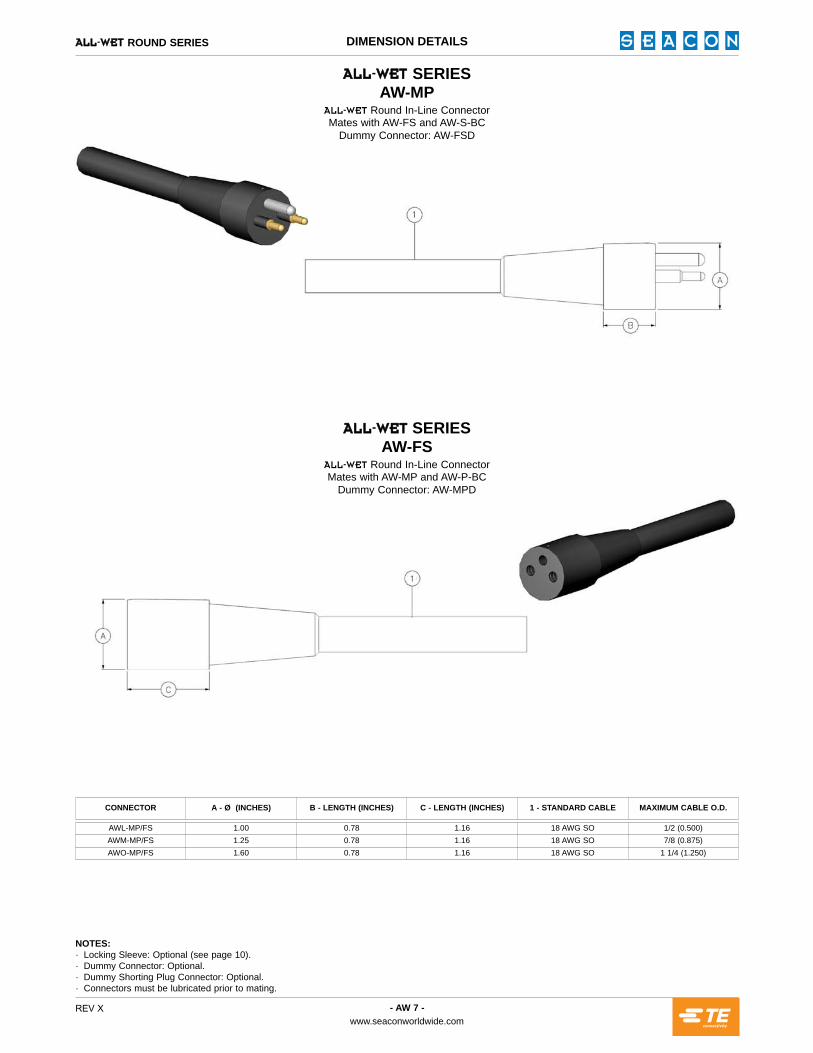
^iiJttbq SERIES AW-MP
^iiJtbq Round In-Line ConnectorMates with AW-FS and AW-S-BC
Dummy Connector: AW-FSD
^iiJttbq SERIES AW-FS
^iiJtbq Round In-Line ConnectorMates with AW-MP and AW-P-BC
Dummy Connector: AW-MPD
AWL-MP/FS 1.00 0.78 1.16 18 AWG SO 1/2 (0.500)AWM-MP/FS 1.25 0.78 1.16 18 AWG SO 7/8 (0.875)AWO-MP/FS 1.60 0.78 1.16 18 AWG SO 1 1/4 (1.250)
CONNECTOR A - Ø (INCHES) B - LENGTH (INCHES) C - LENGTH (INCHES) 1 - STANDARD CABLE MAXIMUM CABLE O.D.
NOTES:· Locking Sleeve: Optional (see page 10).· Dummy Connector: Optional.· Dummy Shorting Plug Connector: Optional.· Connectors must be lubricated prior to mating.

- AW 8 -www.seaconworldwide.com
REV X
^iiJttbq ROUND SERIES DIMENSION DETAILS
^iiJttbq SERIES AW-P-BC with Ground (w/G)
^iiJtbq Round Bulkhead ConnectorMates with AW-FS
Dummy Connector: AW-FSD
^iiJttbq SERIES AW-S-BC with Ground (w/G)
^iiJtbq Round Bulkhead ConnectorMates with AW-MP
Dummy Connector: AW-MPD
AWL-P/S-BC-w/G 1/2-20 UNF-2A 1.00 1.00 0.25 0.78 1.29 1.67 2-114 18 AWG 50AWM-P/S-BC-w/G 3/4-16 UNF-2A 1.25 1.25 0.25 0.78 1.29 1.67 2-118 18 AWG 85AWO-P/S-BC-w/G 1-14 UNS-2A 1.60 1.62 0.50 1.15 2.31 2.69 2-122 8 AWG 125
AWL-P/S-BC-w/G 1/2-20 UNF 1.00 1.00 2-114 18 AWG 15AWL-P/S-BC-w/G 3/4-16 UNS* 1.00 1.25 2-118 18 AWG 50AWM-P/S-BC-w/G 3/4-16 UNF 1.25 1.25 2-118 18 AWG 50AWM-P/S-BC-w/G 1-14 UNS* 1.25 1.50 2-122 18 AWG 85AWO-P/S-BC-w/G 1-14 UNS 1.60 1.62 2-122 8 AWG 85
CONNECTOR A - THREAD B - Ø (INCHES)
C - HEX FLATS(INCHES)
D - LENGTH(INCHES)
E - LENGTH(INCHES)
F - LENGTH(INCHES)
G - LENGTH(INCHES) 1 - O-RING 2 - HOOK-UP
WIREBULKHEAD MOUNTING
TORQUE (INCH POUNDS)
CONNECTOR A - THREAD B - Ø (INCHES) C - HEX FLATS (INCHES) 1 - O-RING 2 - HOOK-UP WIRE BULKHEAD MOUNTING TORQUE(INCH POUNDS)
GRE SPECIAL ORDER SIZES
NOTES:· This series offers a ground pin that will make contact prior to the line pins and break contact last upon demating.· * Optional, more robust design.· Optional thread sizes: AWL-7/16-20 UNF-2A. AWM-5/8-18 UNF-2A.· Bulkhead Locking Sleeve: Optional; Factory installation only for AWL/M/O-BC (see page 10).· Nut and washer: Optional.· Dummy Connector: Optional.· Dummy Shorting Plug Connector: Optional.· Connectors must be lubricated prior to mating.· Torque values referenced in this literature assume installation into dry metal threads. For other applications, please contact pb^`lk for recommendations.· Connectors are designed for installation on one atmosphere vessels. Contact pb^`lk for recommendations if using compensated vessels.

- AW 9 -www.seaconworldwide.com
REV X
^iiJttbq ROUND SERIES DIMENSION DETAILS
^iiJttbq SERIESAW-MP with Ground (w/G)
^iiJtbq Round with Ground In-Line ConnectorMates with AW-FS and AW-S-BC
Dummy Connector: AW-FSD
NOTES:· This series offers a ground pin that will make contact prior to the line pins and break contact last upon demating.· Locking Sleeve: Optional (see page 10).· Dummy Connector: Optional.· Dummy Shorting Plug Connector: Optional.· Connectors must be lubricated prior to mating.· For Bulkhead Connectors, please contact pb^`lk for availability.· AWO-15 w/G has one pin that makes contact last.
^iiJttbq SERIESAW-FS with Ground (w/G)
^iiJtbq Round with Ground In-Line ConnectorMates with AW-MP and AW-P-BC
Dummy Connector: AW-MPD
AWL-MP/FS-w/G 1.00 0.78 1.16 18 AWG SO 1/2 (0.500)AWM-MP/FS-w/G 1.25 0.78 1.16 18 AWG SO 7/8 (0.875)AWO-MP/FS-w/G 1.85 1.39 1.23 8 AWG SO 1 1/4 (1.250)
CONNECTOR A - Ø (INCHES) B - LENGTH (INCHES) C - LENGTH (INCHES) 1 - STANDARD CABLE MAXIMUM CABLE O.D.
STANDARD IN-LINE w/GROUND COLOR CODE
AWO-15 w/G-MP/FS
1 WHITE2 BLACKG GREEN
1 WHITE2 BLACK3 REDG GREEN
1 WHITE2 BLACK3 RED4 ORANGE5 BLUEG GREEN
1 WHITE2 BLACK3 RED4 ORANGE5 BLUE6 WHITE/BLACK7 RED/BLACK8 GREEN/BLACK9 ORANGE/BLACK10 BLUE/BLACK11 BLACK/WHITE12 GREEN/WHITE13 RED/WHITE14 BLUE/WHITE15 BLACK/REDG GREEN
CONTACT # COLOR CONTACT # COLORCONTACT # COLOR CONTACT # COLOR
AWL-2 w/G-MP/FSAWL-3 w/G-MP/FSAWM-3 w/G-MP/FS AWM-5 w/G-MP/FS

- AW 10 -www.seaconworldwide.com
REV X
^iiJttbq ROUND SERIES DIMENSION DETAILS
^iiJttbq SERIESFLS
^iiJtbq Female Locking Sleeve
^iiJttbq SERIESMLS
^iiJtbq Male Locking Sleeve
AWL-FLS AWL-FBLS 1.25 1.23 - 2.10 RR-100AWL-MLS AWL-MBLS 1.25 - 1.38 2.10 RR-100
AWM-FLS AWM-FBLS 1.50 1.23 - 2.10 RR-125AWM-MLS AWM-MBLS 1.50 - 1.38 2.10 RR-125
AWO-FLS AWO-FBLS 1.85 1.23 - 2.10 RR-162AWO-MLS AWO-MBLS 1.85 - 1.38 2.10 RR-162
- AWQ-FBLS 2.50 1.44 - 2.94 -AWQ-MLS - 2.50 - 2.00 2.94 -
^iiJttbq LOCKING SLEEVESIN-LINE BULKHEAD A - Ø (INCHES) B - LENGTH (INCHES) C - LENGTH (INCHES) D - LENGTH (INCHES) E - SPIROLOX
NOTES:· D - Polyacetal.· S - Stainless Steel.· Locking Sleeves will fit standard ^iiJtbq Connectors and ^iiJtbq Split Connectors.· Specify Bulkhead or In-Line type locking sleeve.· Bulkhead Locking Sleeve: Optional.· If locking sleeves are required for AWL/M/O bulkhead connectors, they must be specified at time of connector order as they are factory installations only.
- AW 11 -www.seaconworldwide.com
REV X
^iiJttbq ROUND SERIES INTERFACE DETAILS
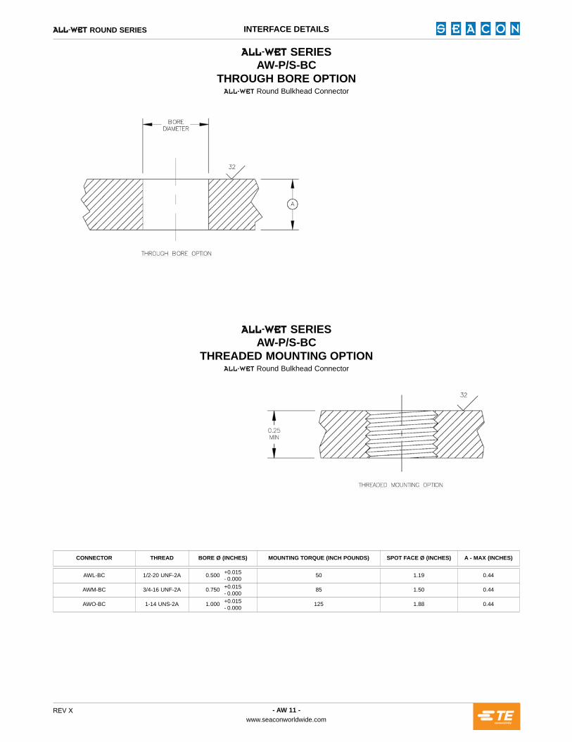
^iiJttbq SERIESAW-P/S-BC
THROUGH BORE OPTION^iiJtbq Round Bulkhead Connector
^iiJttbq SERIESAW-P/S-BC
THREADED MOUNTING OPTION^iiJtbq Round Bulkhead Connector
AWL-BC 1/2-20 UNF-2A 0.500 50 1.19 0.44
AWM-BC 3/4-16 UNF-2A 0.750 85 1.50 0.44
AWO-BC 1-14 UNS-2A 1.000 125 1.88 0.44
CONNECTOR THREAD BORE Ø (INCHES) MOUNTING TORQUE (INCH POUNDS) SPOT FACE Ø (INCHES) A - MAX (INCHES)
+0.015- 0.000+0.015- 0.000+0.015- 0.000

- AW 12 -www.seaconworldwide.com
REV X
^iiJttbq ROUND SERIES CONTACT CONFIGURATIONS
L
M
O
SIZE ^iiJttbq ROUND SERIES CONTACT CONFIGURATIONS (FEMALE FACE VIEW ONLY* - NOT TO SCALE)
2 4***
6 8 8x 3 w/G** 5 w/G**
5 2 w/GRD** 3 w/G**3
12S 3 w/G** 15 w/G**
NOTES:· * For male face view contact configurations available please contact pb^`lk.· ** ^iiJtbq series w/Ground.· *** AWL-4-S mates with AWL-2/4-MP Split connectors.

^iiJtbq SPLIT SERIES
UNDERWATER ELECTRICAL WET-MATE CONNECTORS

D - PolyacetalS - Stainless Steel
MLS - Male Locking SleeveFLS - Female Locking Sleeve
Shell Size (L, M, O, Q, R)
^iiJtbq Split Series
A W Q - M L S - D
Bulkhead Connector
Socket
Total Number of Contacts
Number of Contacts per Sector
Size (L, M, O, Q, R)
^iiJtbq Split Series
A W Q - 4 / 2 4 - S - B C
Dummy Connector
Male Plug
Total Number of Contacts
Number of Contacts per Sector
Size (L, M, O, Q, R)
^iiJtbq Split Series
A W Q - 4 / 2 4 - M P - D
- AW 14 -www.seaconworldwide.com
REV X
^iiJttbq SPLIT SERIES
GENERAL INFORMATIONCATEGORY VALUECOMPONENT MATERIAL
OPEN FACE PRESSURE Up to 1,000 psi
MATED PRESSURE Up to 10,000 psi
VOLTAGE Will vary by pattern, determined by the cable
CURRENT Up to 13 amps per contact**
CONTACT RESISTANCE <0.01 ohms
INSULATION RESISTANCE >500 megohms after wet mating
MATING CYCLES >500 wet matings***
BULKHEAD BODY: STANDARD:OPTIONAL:
CA630 per QQ-C-465*Many materials including 316 Stainless Steel, 6A14V Titanium, Glass Reinforced Epoxy (GRE)
CONNECTOR BODY: STANDARD:OPTIONAL:
Neoprene per B/A X5727Hypalon per B/A X6830
CONTACTS Copper Alloy Gold Plated per ASTM B488
GUIDE PINS 304 Stainless Steel
O-RINGS Nitrile (formerly known as Buna N)
NOTES:· * Except AWM-2/12S-BC (Standard = 316 Stainless Steel).· ** Maximum current carrying capacity for contacts may be affected by cable selection.· *** Provided proper handling procedures are adhered to.· Locking sleeves are not standard and must be ordered separately. Available in Polyacetal or Stainless Steel.· Bulkhead nut/washer is not standard and must be ordered separately. Available in Stainless Steel.
Please see page 15 of this ^iiJtbq Split section.
AMPACITY CHART FOR STANDARD PARTS
STANDARD IN-LINE WIRING COLOR CODE (SO CABLE)
1 WHITE2 BLACK3 GREEN4 RED5 ORANGE6 BLUE
CONTACT # COLOR
7 WHITE/BLACK8 RED/BLACK9 GREEN/BLACK10 ORANGE/BLACK11 BLUE/BLACK12 BLACK/WHITE
CONTACT # COLOR
PART NUMBER SYSTEM - EXAMPLE
^iiJttbq SPLIT SERIES LOCKING SLEEVESLocking sleeves are available for ALL-WET Split Series connectors as anoption, see page 10.
^iiJttbq SPLIT SERIES BULKHEAD CONNECTORS ^iiJttbq SPLIT SERIES IN-LINE CONNECTORS
MP - Male Plug
Total Number of Contacts
Number of Contacts per Sector
Shell Size (L, M, O, Q, R)
^iiJtbq Split Series
A W Q - 4 / 2 4 - M P
^iiJttbq SPLIT SERIES DUMMY CONNECTORSDummy male plug connectors are available for all bulkhead connectors in the^iiJtbq Split Series. To order, add the suffix-D after the part number.
UNDERWATER ELECTRICAL WET-MATE CONNECTORS
- AW 15 -www.seaconworldwide.com
REV X
^iiJttbq SPLIT SERIES DIMENSION DETAILS
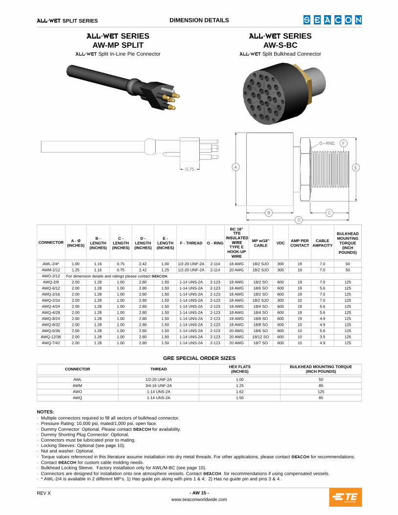
^iiJttbq SERIESAW-MP SPLIT
^iiJtbq Split In-Line Pie Connector
^iiJttbq SERIESAW-S-BC
^iiJtbq Split Bulkhead Connector
AWL-2/4* 1.00 1.16 0.75 2.42 1.00 1/2-20 UNF-2A 2-114 18 AWG 18/2 SJO 300 19 7.0 50AWM-2/12 1.25 1.16 0.75 2.42 1.25 1/2-20 UNF-2A 2-114 20 AWG 18/2 SJO 300 19 7.0 50AWO-2/12 For dimension details and ratings please contact pb^`lk.AWQ-2/8 2.00 1.28 1.00 2.80 1.50 1-14 UNS-2A 2-123 18 AWG 18/2 SO 600 19 7.0 125AWQ-6/12 2.00 1.28 1.00 2.80 1.50 1-14 UNS-2A 2-123 18 AWG 18/6 SO 600 19 5.6 125AWQ-2/16 2.00 1.28 1.00 2.80 1.50 1-14 UNS-2A 2-123 18 AWG 18/2 SO 600 19 7.0 125AWQ-2/24 2.00 1.28 1.00 2.80 1.50 1-14 UNS-2A 2-123 18 AWG 18/2 SJO 300 10 7.0 125AWQ-4/24 2.00 1.28 1.00 2.80 1.50 1-14 UNS-2A 2-123 18 AWG 18/4 SO 600 19 5.6 125AWQ-4/28 2.00 1.28 1.00 2.80 1.50 1-14 UNS-2A 2-123 18 AWG 18/4 SO 600 19 5.6 125AWQ-8/24 2.00 1.28 1.00 2.80 1.50 1-14 UNS-2A 2-123 18 AWG 18/8 SO 600 19 4.9 125AWQ-8/32 2.00 1.28 1.00 2.80 1.50 1-14 UNS-2A 2-123 18 AWG 18/8 SO 600 10 4.9 125AWQ-6/36 2.00 1.28 1.00 2.80 1.50 1-14 UNS-2A 2-123 20 AWG 18/6 SO 600 10 5.6 125AWQ-12/36 2.00 1.28 1.00 2.80 1.50 1-14 UNS-2A 2-123 20 AWG 18/12 SO 600 10 3.5 125AWQ-7/42 2.00 1.28 1.00 2.80 1.50 1-14 UNS-2A 2-123 20 AWG 18/7 SO 600 10 4.9 125
CONNECTOR A - Ø(INCHES)
B - LENGTH (INCHES)
C -LENGTH(INCHES)
D -LENGTH(INCHES)
E - LENGTH(INCHES)
F - THREAD O - RING
BC 18”TFE
INSULATED WIRE
TYPE EHOOK-UP
WIRE
MP w/18”CABLE VDC AMP PER
CONTACTCABLE
AMPACITY
BULKHEADMOUNTING
TORQUE(INCH
POUNDS)
AWL 1/2-20 UNF-2A 1.00 50AWM 3/4-16 UNF-2A 1.25 85AWO 1-14 UNS-2A 1.62 125AWQ 1-14 UNS-2A 1.50 85
CONNECTOR THREAD HEX FLATS(INCHES)
BULKHEAD MOUNTING TORQUE(INCH POUNDS)
GRE SPECIAL ORDER SIZES
NOTES:· Multiple connectors required to fill all sectors of bulkhead connector.· Pressure Rating: 10,000 psi, mated/1,000 psi, open face.· Dummy Connector: Optional. Please contact pb^`lk for availability.· Dummy Shorting Plug Connector: Optional.· Connectors must be lubricated prior to mating.· Locking Sleeves: Optional (see page 10).· Nut and washer: Optional.· Torque values referenced in this literature assume installation into dry metal threads. For other applications, please contact pb^`lk for recommendations.· Contact pb^`lk for custom cable molding needs.· Bulkhead Locking Sleeve. Factory installation only for AWL/M-BC (see page 10).· Connectors are designed for installation onto one atmosphere vessels. Contact pb^`lk for recommendations if using compensated vessels.· * AWL-2/4 is available in 2 different MP’s. 1) Has guide pin along with pins 1 & 4; 2) Has no guide pin and pins 3 & 4.

- AW 16 -www.seaconworldwide.com
REV X
^iiJttbq SPLIT SERIES CONTACT CONFIGURATIONS
2
3
4
6
7
8
12
SIZE ^iiJttbq SPLIT SERIES CONTACT CONFIGURATIONS (FEMALE FACE VIEW ONLY - NOT TO SCALE)
AWL 2/4*
AWQ 6/12
AWQ 2/8 AWQ 8/32
AWQ 4/24
AWO 2/12AWM 2/12
AWQ 6/36 AWQ 7/42
AWQ 4/28
AWQ 2/16
AWQ 2/24
AWQ 8/24 AWQ 12/36
NOTES:· All configurations shown are the face view of the Bulkhead Connector (BC). Standard bulkhead contacts are female.· The mating male plugs (MP) are “split” into equally shaped sections.· For customer configurations or special applications contact pb^`lk or sales representative.· * AWL-2/4-MP mates with standard AWL-4S-BC.

^iiJtbq FLAT SERIES
UNDERWATER ELECTRICAL WET-MATE CONNECTORS
- AW 18 -www.seaconworldwide.com
REV X
^iiJttbq FLAT & HERMAPHRODITIC SERIES
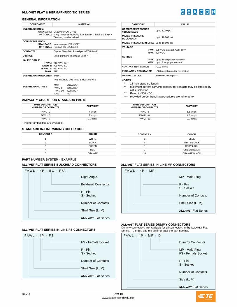
GENERAL INFORMATIONCOMPONENT MATERIAL
OPEN FACE PRESSURE#BULKHEADS Up to 1,000 psi
MATED PRESSUREBULKHEADS Up to 10,000 psi
MATED PRESSURE IN-LINES Up to 10,000 psi
VOLTAGEFAW:
MAW:600 VDC except FAWM-10***300 VDC
CURRENTFAW:
MAW:Up to 10 amps per contact**Up to 3 amps per contact**
CONTACT RESISTANCE <0.01 ohms
INSULATION RESISTANCE >500 megohms after wet mating
MATING CYCLES >500 wet matings****
BULKHEAD BODY: STANDARD: OPTIONAL:
CA630 per QQ-C-465Many materials including 316 Stainless Steel and 6A14V Titanium, Hard Anodized
CONNECTOR BODY: STANDARD: OPTIONAL:
Neoprene per B/A X5727Hypalon per B/A X6830
CONTACTS Copper Alloy Gold Plated per ASTM B488
O-RINGS Nitrile (formerly known as Buna N)
IN-LINE CABLE:#18 AWG SO*#20 AWG SO*#22 AWG SO*IN2*
BULKHEAD NUT/WASHER Brass
BULKHEAD PIGTAILS
TFE insulated wire Type E Hook-up wire
FAWL #18 AWG*FAWM 8 #20 AWG*FAWM 10 #22 AWG*MAW IN2*
NOTES:· *· **
· ***· ****
18 inch standard length.Maximum current carrying capacity for contacts may be affected by cable selection.Rated to 300 VDC.Provided proper handling procedures are adhered to.
· Higher ampacities are available.
AMPACITY CHART FOR STANDARD PARTS
FAWL - 2 7 ampsFAWL - 3 7 ampsFAWL - 4 5.6 amps
PART DESCRIPTION NUMBER OF CONTACTS AMPACITY
FAWL - 5 5.6 ampsFAWM - 8 4.9 ampsFAWM - 10 2.5 amps
PART DESCRIPTION NUMBER OF CONTACTS AMPACITY
STANDARD IN-LINE WIRING COLOR CODE
1 WHITE2 BLACK3 GREEN4 RED5 ORANGE
CONTACT # COLOR
6 BLUE7 WHITE/BLACK8 RED/BLACK9 GREEN/BLACK10 ORANGE/BLACK
CONTACT # COLOR
CATEGORY VALUE
FA W L - 4 P - M P - DFA W L - 4 P - F S
PART NUMBER SYSTEM - EXAMPLE^iiJttbq FLAT SERIES BULKHEAD CONNECTORS ^iiJttbq FLAT SERIES IN-LINE MP CONNECTORS
^iiJttbq FLAT SERIES IN-LINE FS CONNECTORS^iiJttbq FLAT SERIES DUMMY CONNECTORSDummy connectors are available for all connectors in the ^iiJtbq FlatSeries. To order, add the suffix-D after the part number.
Right Angle
Bulkhead Connector
P - PinS - Socket
Number of Contacts
Shell Size (L, M)
^iiJtbq Flat Series
FA W L - 4 P - B C - R / A
FS - Female Socket
P - PinS - Socket
Number of Contacts
Shell Size (L, M)
^iiJtbq Flat Series
MP - Male Plug
P - PinS - Socket
Number of Contacts
Shell Size (L, M)
^iiJtbq Flat Series
FA W L - 4 P - M P
Dummy Connector
MP - Male PlugFS - Female Socket
P - PinS - Socket
Number of Contacts
Size (L, M)
^iiJtbq Flat Series
FAWL:FAWM 8:
FAWM 10:MAW:
- AW 19 -www.seaconworldwide.com
REV X
^iiJttbq FLAT SERIES DIMENSION DETAILS
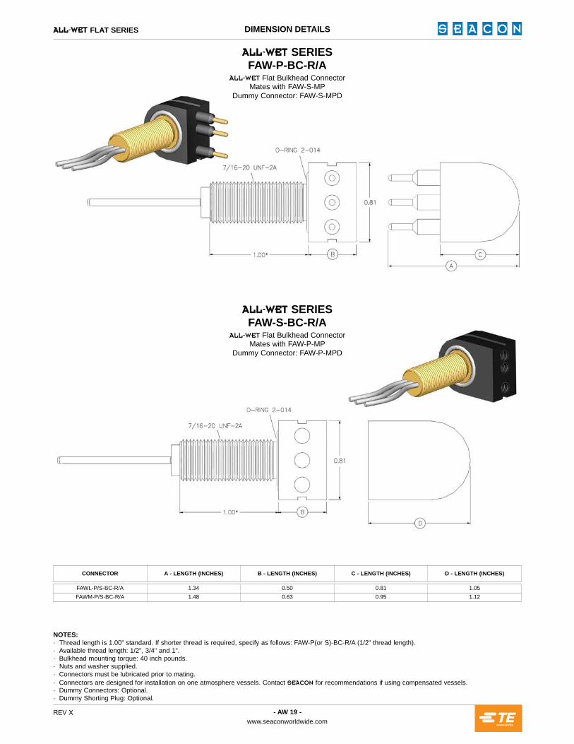
^iiJttbq SERIESFAW-P-BC-R/A
^iiJtbq Flat Bulkhead ConnectorMates with FAW-S-MP
Dummy Connector: FAW-S-MPD
^iiJttbq SERIESFAW-S-BC-R/A
^iiJtbq Flat Bulkhead ConnectorMates with FAW-P-MP
Dummy Connector: FAW-P-MPD
NOTES:· Thread length is 1.00" standard. If shorter thread is required, specify as follows: FAW-P(or S)-BC-R/A (1/2" thread length).· Available thread length: 1/2", 3/4" and 1".· Bulkhead mounting torque: 40 inch pounds.· Nuts and washer supplied.· Connectors must be lubricated prior to mating.· Connectors are designed for installation on one atmosphere vessels. Contact pb^`lk for recommendations if using compensated vessels.· Dummy Connectors: Optional.· Dummy Shorting Plug: Optional.
CONNECTOR A - LENGTH (INCHES) B - LENGTH (INCHES) C - LENGTH (INCHES) D - LENGTH (INCHES)
FAWL-P/S-BC-R/A 1.34 0.50 0.81 1.05FAWM-P/S-BC-R/A 1.48 0.63 0.95 1.12
- AW 20 -www.seaconworldwide.com
REV X
^iiJttbq FLAT SERIES DIMENSION DETAILS
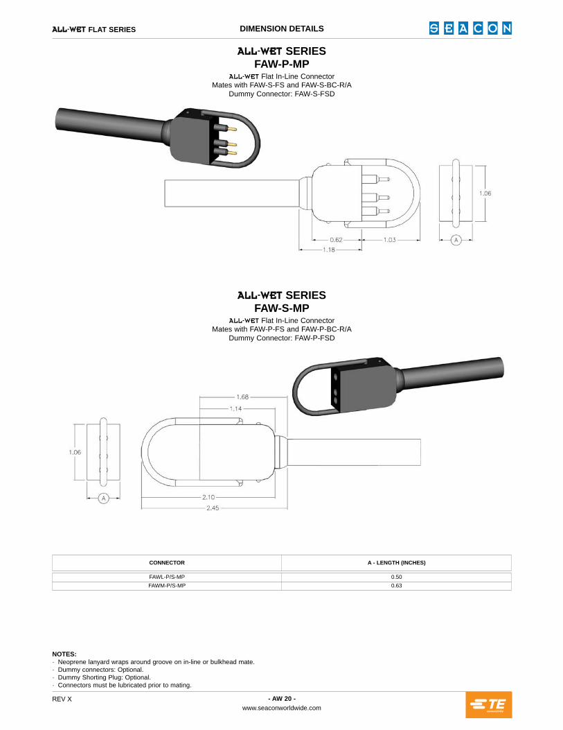
^iiJttbq SERIESFAW-P-MP
^iiJtbq Flat In-Line ConnectorMates with FAW-S-FS and FAW-S-BC-R/A
Dummy Connector: FAW-S-FSD
^iiJttbq SERIESFAW-S-MP
^iiJtbq Flat In-Line ConnectorMates with FAW-P-FS and FAW-P-BC-R/A
Dummy Connector: FAW-P-FSD
NOTES:· Neoprene lanyard wraps around groove on in-line or bulkhead mate.· Dummy connectors: Optional.· Dummy Shorting Plug: Optional.· Connectors must be lubricated prior to mating.
CONNECTOR A - LENGTH (INCHES)
FAWL-P/S-MP 0.50FAWM-P/S-MP 0.63

- AW 21 -www.seaconworldwide.com
REV X
^iiJttbq FLAT SERIES DIMENSION DETAILS
^iiJttbq SERIESFAW-P-FS
^iiJtbq Flat In-Line ConnectorMates with FAWL-S-MP
Dummy Connector: FAW-S-MPD
^iiJttbq SERIESFAW-S-FS
^iiJtbq Flat In-Line ConnectorMates with FAWL-P-MP
Dummy Connector: FAW-P-MPD
NOTES:· Dummy Connector: Optional.· Dummy Shorting Plug: Optional.· Connectors must be lubricated prior to mating.
CONNECTOR A - LENGTH (INCHES) B - LENGTH (INCHES) C - LENGTH (INCHES) D - LENGTH (INCHES) E - LENGTH (INCHES) F - LENGTH (INCHES)
FAWL-P/S-FS 0.81 0.50 0.88 1.31 1.05 1.55FAWM-P/S-FS 0.98 0.63 0.94 1.33 1.15 1.52
- AW 22 -www.seaconworldwide.com
REV X
^iiJttbq HERMAPHRODITIC SERIES DIMENSION DETAILS
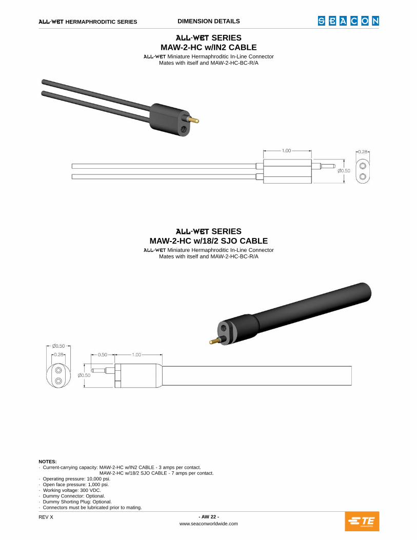
^iiJttbq SERIESMAW-2-HC w/IN2 CABLE
^iiJtbq Miniature Hermaphroditic In-Line ConnectorMates with itself and MAW-2-HC-BC-R/A
^iiJttbq SERIESMAW-2-HC w/18/2 SJO CABLE
^iiJtbq Miniature Hermaphroditic In-Line ConnectorMates with itself and MAW-2-HC-BC-R/A
NOTES:· Current-carrying capacity: MAW-2-HC w/IN2 CABLE - 3 amps per contact.
MAW-2-HC w/18/2 SJO CABLE - 7 amps per contact.· Operating pressure: 10,000 psi.· Open face pressure: 1,000 psi.· Working voltage: 300 VDC.· Dummy Connector: Optional.· Dummy Shorting Plug: Optional.· Connectors must be lubricated prior to mating.
- AW 23 -www.seaconworldwide.com
REV X
^iiJttbq HERMAPHRODITIC SERIES DIMENSION DETAILS
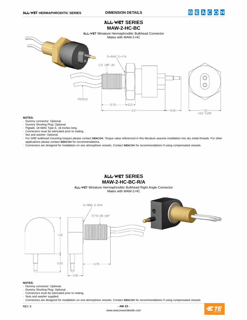
^iiJttbq SERIESMAW-2-HC-BC
^iiJtbq Miniature Hermaphroditic Bulkhead ConnectorMates with MAW-2-HC
^iiJttbq SERIESMAW-2-HC-BC-R/A
^iiJtbq Miniature Hermaphroditic Bulkhead Right Angle ConnectorMates with MAW-2-HC
NOTES:· Dummy connector: Optional.· Dummy Shorting Plug: Optional.· Connectors must be lubricated prior to mating.· Nuts and washer supplied.· Connectors are designed for installation on one atmosphere vessels. Contact pb^`lk for recommendations if using compensated vessels.
NOTES:· Dummy connector: Optional.· Dummy Shorting Plug: Optional.· Pigtails: 18 AWG Type E, 18 inches long.· Connectors must be lubricated prior to mating.· Nut and washer: Optional.· For GRE bulkhead mounting torques please contact pb^`lk. Torque value referenced in this literature assume installation into dry metal threads. For other
applications please contact pb^`lk for recommendations.· Connectors are designed for installation on one atmosphere vessels. Contact pb^`lk for recommendations if using compensated vessels.

- AW 24 -www.seaconworldwide.com
REV X
^iiJttbq FLAT SERIES UNDERWATER ELECTRICAL WET-MATE CONNECTORS
^iiJttbq SERIESFAW-P/S-BC
THROUGH BORE OPTION^iiJtbq Flat Bulkhead Connector
^iiJttbq SERIESFAW-P/S-BC
THREADED MOUNTING OPTION^iiJtbq Flat Bulkhead Connector
NOTES:· A - Spot face to 32 finish, minimum diameter 1.25 (to be equal to or greater than connector diameter).
· Bore, through or threaded, must be perpendicular to spot face.· If threaded mount is used, the lead thread chamfer is not to exceed diameter 0.450.

- AW 25 -www.seaconworldwide.com
REV X
^iiJttbq FLAT SERIES CONTACT CONFIGURATIONS
L
SIZE
SIZE
SIZE
M
L
M
L
M
^iiJttbq FLAT SERIES RIGHT ANGLE BULKHEAD CONTACT CONFIGURATIONS (NOT TO SCALE)
^iiJttbq FLAT SERIES IN-LINE CONTACT CONFIGURATIONS (NOT TO SCALE)
^iiJttbq FLAT SERIES IN-LINE CONTACT CONFIGURATIONS (NOT TO SCALE)
FAWL-2P-BC-R/A FAWL-2S-BC-R/A FAWL-3P-BC-R/A FAWL-3S-BC-R/A FAWL-4P-BC-R/A FAWL-4S-BC-R/A FAWL-5P-BC-R/A FAWL-5S-BC-R/A
FAWL-2P-MP FAWL-2S-MP FAWL-3P-MP FAWL-3S-MP FAWL-4P-MP FAWL-4S-MP FAWL-5P-MP FAWL-5S-MP
FAWL-2P-FS FAWL-2S-FS FAWL-3P-FS FAWL-3S-FS FAWL-4P-FS FAWL-4S-FS FAWL-5P-FS FAWL-5S-FS
FAWM-8P-BC-R/A FAWM-8S-BC-R/A FAWM-10P-BC-R/A FAWM-10S-BC-R/A
FAWM-8P-MP FAWM-8S-MP FAWM-10P-MP FAWM-10S-MP
FAWM-8P-FS FAWM-8S-FS FAWM-10P-FS FAWM-10S-FS
Even though these procedures appear simple, only qualified techni-cians should perform the installation and maintenance. Connectors aredesigned for installation on one atmosphere vessels. Contact pb^`lkfor recommendations if using compensated vessels.
INSTALLATION PROCEDURESTorque values referenced in this literature assume installation into drymetal threads. For other applications, please contact pb^`lk for rec-ommendations. BULKHEAD CONNECTOR (BC): The BC may be installed using oneof two methods. The preferred method is to spotface the bulkhead sur-face and thread the hole, then screw the connector by means of a nutand washer. The bored hole (or threaded hole) should be free of any“burrs” and all o-ring sealing surfaces polished to a number 32 finish.Lubricate the BC o-ring with an appropriate silicone spray or greasebefore installing. This lubrication should be applied to form an ade-quate film. Excessive lubrication is detrimental to the operation of theconnector. Bulkhead nut, if used, should not be over-torqued.IN-LINE CONNECTOR: Lubricate the sealing areas around the malepins, using an appropriate silicone spray, or grease lightly.
CARE AND MAINTENANCEThe ^iiJtbq connectors require very little maintenance. They aredesigned to be used in harsh environments and thus limited amountsof dirt and grit do not affect their performance.
It is recommended that, upon disconnecting or retrieving the system,the connectors be cleaned, to storage (if possible, remate with dummyplugs). Prior to deployment the following maintenance procedure isrecommended:
1.2.
3.
4.
5.
HANDLING PROCEDURES AND SPECIAL CAPABILITIES
* CAUTION: The use of some oil-based propellants in spray cans cancause conductivity problems in neoprene.
CABLE AND CONTINUITY PRESERVATIONAvoid sharp bends in cables. Cables subjected to vibration or exposedto seawater drag should be adequately clamped to prevent conductorfatigue and ultimate failure.
All reasonable efforts have been taken to ensure that the information contained herein is accurate at the date of publication, but no representation or warranty as to the accuracy or completeness of such information is intended or to be implied by its inclusion herein. Any and all representations and warranties pertaining to the information and products referred to herein shall be set forth in pb^`lk standard sales order form. In addition, pb^`lk reserves the right to make changes to the contents hereof without notice, therefore it is suggested that at the time of inquiry, the appropriate sales office or factory be contacted directly for verification of published specifications and products availability.
© 2017 pb^`lkALL RIGHTS RESERVED
Demate the connector set.Flush connector interface with fresh water (deionized water if available), remove all dirt, grit and grease.Inspect for damage in sealing areas, excessive corrosion, debonding of the cable and connector interface and cuts in the cable jacket.Apply thin film of dilectric compound (DC) grease, silicon based, tosealing areas of male connector and across the face of the femaleconnector*. If the BC is removed from it’s housing then replacefacial o-ring and make sure that o-rings are lubricated and in goodcondition.Mate the connector halves, wipe away any excess grease off theinterface line of the mated set.
pb^`lk GLOBAL PRODUCTIONCallejon Terrazos #8, Local 2-C, Las Brisas 1ra. Seccion,Tijuana, B.C., Mexico C.P. 22610.TEL: +52 (664) 626-2726FAX: +52 (664) 686-8922E-Mail: [email protected]: www.seaconglobal.comDial from U.S.A. TEL: +1 (619) 308-7901TOLL FREE: (888) 562-7072FAX: +1 (619) 308-7900
pb^`lk (europe) LTDSeacon House, Hewett Road, Gapton Hall Industrial Estate,Great Yarmouth, Norfolk, NR31 0RB, UK.TEL: +44 (0) 1493-652733FAX: +44 (0) 1493-652840E-Mail: [email protected]: www.seaconeurope.com
pb^`lk1700 Gillespie Way,El Cajon, California 92020, USA.TEL: +1 (619) 562-7071FAX: +1 (619) 562-9706E-Mail: [email protected]: www.seaconworldwide.com
pb^`lk US GULF AREA SALES OFFICE14511 Old Katy Road, Suite 300,Houston, Texas 77079, USA. TEL: +1 (281) 599-3509FAX: +1 (281) 599-3517E-Mail: [email protected]: www.seaconworldwide.com
pb^`lk ADVANCED PRODUCTS, LLC1321 Nelius Road, P.O. Box 767,Bellville, Texas 77418, USA.TEL: +1 (979) 865-8846FAX: +1 (979) 865-8859E-Mail: [email protected]: www.seacon-ap.com
pb^`lk BRAZILRua Conde de Bonfim 120 sala 212, Tijuca,Rio de Janeiro, Brazil, CEP: 20520-053.TEL: +55 (11) 2103-6262CELL: +55 (21) 9-7626-6062E-mail: [email protected]: www.seaconworldwide.com
pb^`lk PHOENIX15 Gray Lane, Suite 108, Hopkinton Industrial Park,Ashaway, Rhode Island 02804, USA.TEL: +1 (401) 637-4952 FAX: +1 (401) 637-4953E-Mail: [email protected]: www.seaconphoenix.com
REV X